

Moxa Technologies NPort W2150A-T, NPort W2250A, NPort W2150A, NPort W2250A-T Quick Installation Manual
Page 1
– 1 – – 2 – – 3 –
P/N: 1802021503010
NPort W2150A/W2250A Series
Quick Installation Guide
First Edition, April 2012
1. Overview
The NPort W2150A /W2250A wireless device servers are an ideal
choice for connecting serial devices such as PLCs, meters, and
sensors to an IP-based wireless LAN or Ethernet LAN.
Features
• Link any serial d evice to an IEEE 802.11a/b/g net work.
• 1 and 2-port RS-232/422/485 models, up to 921.6 Kbps.
• Web-based configuration over Ethernet or wireless LAN.
• Enhanced security for remote configuration with HTTPS, SSH.
• Secure data access with WEP, WPA, WPA2.
• Built-in WLAN site survey tool.
• Fast roaming when signal strength is weak.
• Per-port offline port buffering and serial data log.
• Dual power inputs via power jack and terminal block.
2. Package Checklist
Before installin g the NPort W2150 A/W2250A device server, verify
that the package contains the following items:
• 1 NPort W2150A, NPort W2150A-T, NPort W2250A, or
NPort W2250A-T.
• Document and Software CD.
• RJ45 to RJ45 cross-over Ethernet cable.
• Warranty Statement.
• Quick Installat ion Guide.
Optional Accessories
• DK-35A (35 mm DIN-Rail Mo unting Kit).
• Power jack to terminal blo ck power cable
(P/N: 9199000000900).
Note: Notify your sales representative if any of the above items are
missing or damaged.
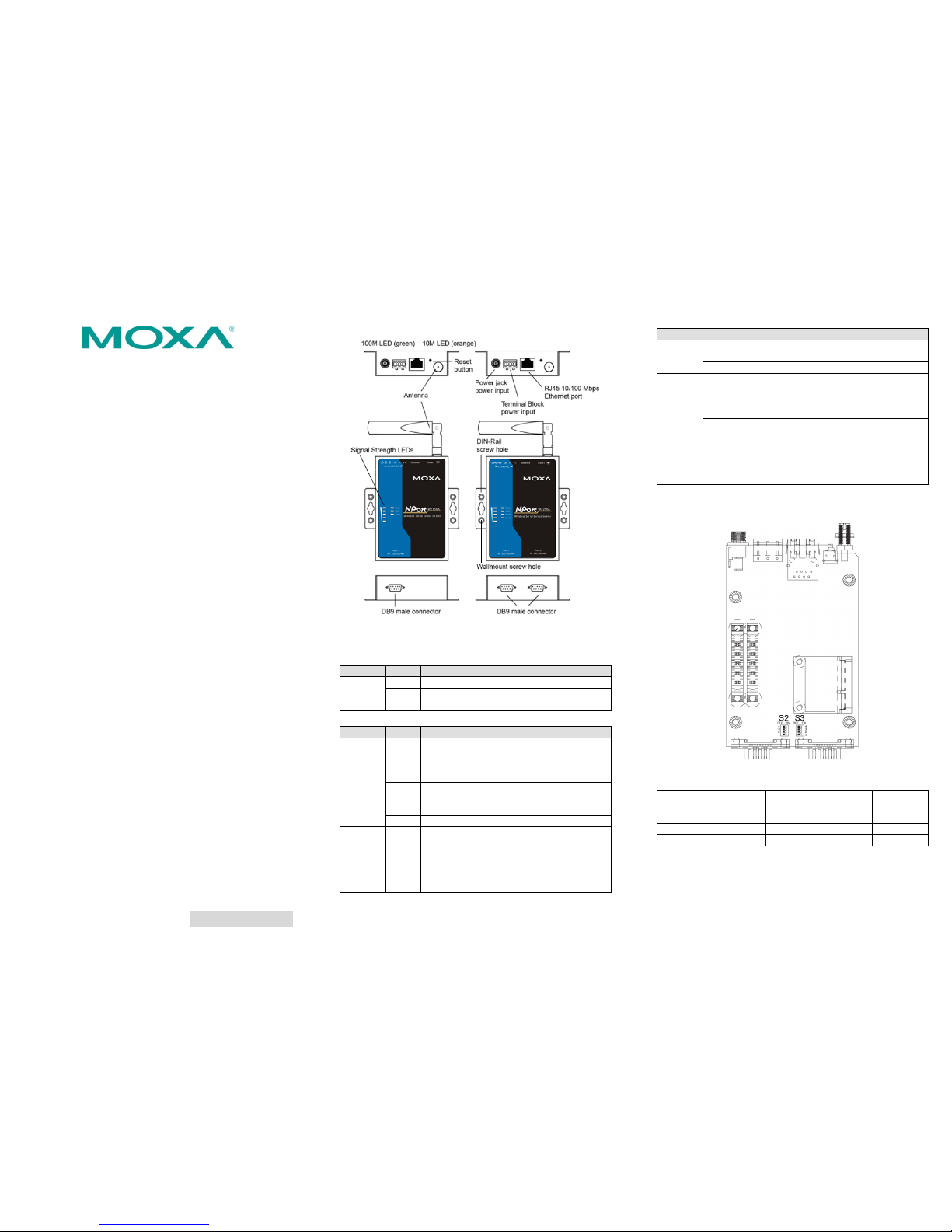
3. Hardware Introduction
The NPort W2150A models have one serial port, and the NPort
W2250A models have two serial ports. All models support
RS-232/422/485 operation with DB9 connectors, and include one
10/100M Ethernet port.
NPort W2150A/W2150A-T
NPort W2250A/W2250A-T
Reset Button—The reset button is used to load factory default
settings. Use a pointed object to hold the reset button down for 5
seconds to load factory defaults.
End Panel LED Indicators
Name
Color
Function
Ethernet
Orange
10 Mbps Ethernet connection
Green
100 Mbps Ethernet connection
Off
Ethernet cable is disconnected
Top Panel LED Indicators
Name
Color
Function
Ready
Red
Steady on:
Power is on and NPort is booting
up
Blinking:
IP conflict or DHCP/BOOTP server
did not respond properly
Green
Steady on:
NPort is functioning normally
Blinking: NPort is responding to Locate
function
Off
Power is off or a power error condition exists
WLAN
Green
Steady on:
Wireless enabled
Blinking:
NPort can’t establish WLAN
connection with AP
(Infrastructure) or station
(Ad-Hoc)
Off
Wireless not enabled
Name
Color
Function
Serial 1
Serial 2
Orange
Serial port is re ceiving data
Green
Serial port is tr ansmitting data
Off
No data is flowing to or from the serial port
Signal
Strength
Red
1 Red -
the signal strength is between 0%
to 20%
2 Red - the signal streng th is between 21 %
to 40%
Green
3 Green -
the signal streng th is between 41 %
to 60%
4 Green -
the signal streng th is between 61%
to 80%
5 Green - the signal streng th is between 81 %
to 100%
4. Pull High/Low Resistors and Terminal
Resistor for RS-422/485
You may need to set the pull high/low resistors when termination
resistors are used for certain RS-422 or RS-485 environments.
S2(Serial 1)
S3(Serial 2)
DIP 1
DIP 2
DIP 3
DIP 4
Pull high
Resistor
Pull low
Resistor
Terminal
Resistor
Reserved
ON
1K Ω
1K Ω
120 Ω
-----
OFF
*150K Ω
*150K Ω
*N/A
-----
* Default
S3 is for NPort W 2250A only.
Page 2

– 4 – – 5 – – 6 –
www.moxa.com/support
The Americas:
+1-714-528-6777 (toll-free: 1-888-669-2872)
Europe:
+49-89-3 70 03 99-0
Asia-Pacific:
+886-2-8919-1230
China:
+86-21-5258-9955 (toll-free: 800-820-5036)
2012 Moxa Inc. All r ights reserved.
NOTE Do not use the 1 KΩ setting while in RS-232 mode. Doing
so will degrade the RS-232 signals and reduce the effective
communication distance.
5. First-time Hardware Installation
STEP 1:
After removing the NPort W2150A/W2250A from the box,
use a cross
-over Ethernet cable to connect the NPort’s
RJ45 Ethernet port directly to your computer’s Ethernet
port.
STEP 2:
Attach the power adaptor to the NPort and then plug the
adaptor into an electrical outlet.
STEP 3:
Configure the NPort W2150A/W2250A through the
Ethernet port. See the next section for software
installation in formation.
NOTE
You must connect the Ethernet cable first before powering
up your NPort
6. Software Installation Information
Insert the Document & Software CD into your PC. A window should
open with severa l options displa yed:
• Click [Install COM Driver] an d follow the on-s creen
instructions to install the COM drivers.
• Click [Documents] and select “NPort W2150A/W2250A
Series User’s Manual” to view the user’s manual.
• Click [Install UTILITY] and follo w the on-screen instructions
to install the NP ort Search Utilit y. This utility can be used to
search for NPort W2150A/W2250A units on the network.
7. Setting the IP Address
The factory default IP settings are assigned as follows:
LAN: Static; IP = 192.168.126.254; netmask = 255.255.255.0
WLAN: Static; IP = 192.168.127.254; netmask = 255.255.255.0
If the NPort is configured for DHCP but the DHCP server cannot be
found, the NPort will use factory default IP settings.
NOTE
If you have forgotten the NPort’s IP address, use the NPort
Search Utility from your PC to locate the NPort. Aft
er
searching the LAN for NPort units, the NPort Search Utility
will display the IP address of ea ch unit.
NOTE
Only one network interface can be active at a time. If the
Ethernet link is a ctive, the WLA N will be inactive . If the
WLAN is active, the Ethernet link will be inactive .
Open the web console to make configuration changes as follows:
STEP 1:
Open your web browser.
STEP 2:
In the address bar, enter 192.168.126.254 (the default
IP address).
STEP 3:
The web console will open, and the current configuration
settings are shown.
STEP 4:
For first time use, click the Wizard in the left navigation
panel. The wizard will prompt you to configure the IP
address, SSID, and security mode. For other settings,
use the factory defaults or modify the settings for your
application.
8. Pin Assignments and Cable Wiring
Pin RS-232
RS-422,
4w RS-485
2w RS-485
1
DCD
TxD-(A)
---
2
RXD
TxD+(B)
---
3
TXD
RxD+(B)
Data+(B)
4
DTR
RxD-(A)
Data-(A)
5
GND
GND
GND
6
DSR
---
---
7
RTS
---
---
8
CTS
---
---
9
---
---
---
Female DB9 to Male DB9
Female DB9 to Male DB25
9. Specifications
Power Requirements
Power Input
12 to 48 VDC
Power Consumption
237mA @ 12V
Power Con nector
Screw type power jack and terminal
block
Physical Characteristics
Material
Aluminum sheet metal (1 mm)
Dimensions
77 × 111 × 26 mm (no ears, no antenna)
100 × 111 × 26 mm
(with ears, no antenna )
Antenna Length
109 mm
Magnetic Isola tion
1.5 KV magnetic isolation built- in
Environmental Limits
Operating Temperature
Standard Models:
0 to 55°C (32 to 131°F), 5 to 95%RH
Wide Temp. Model
s:
-40 to 75°C (-40 to 167°F), 5 to 95%RH
Storage Temperature
-40 to 85°C (-40 to 185°F), 5 to 95%RH
Regulatory Approvals
EMC
CE: EN 55022 Class A/EN 55024
ETSI EN 301 489-17,
ETSI EN 301 489-1
FCC:
FCC Part 17 Subpart B, Class A
FCC Part 15 Subpart B, Class A
Safety UL:
UL 60950-1
LVD
: EN 60950-1
DSPR: ARIB-STD 33, ARIB-STD 66
 Loading...