

Moxa Technologies NPort S8455I, NPort S8455I-MM-SC, NPort S8455I-MM-SC-T, NPort S8455I-T, NPort S8455I-SS-SC User Manual
Page 1

NPort S8000 Series User’s Manual
Edition 7.0, November 2017
www.moxa.com/product
© 2017 Moxa Inc. All rights reserved.
Page 2

NPort S8000 Series User’s Manual
Moxa
Toll
Tel:
Fax:
Moxa China (Shanghai office)
Toll
Tel:
Fax:
Moxa Europe
Tel:
Fax: +49-89-3 70 03 99-99
Moxa As
Tel:
Fax: +886-2-8919-1231
Moxa India
Tel:
Fax:
The software described in this manual is furnished under a license agreement and may be used only in accordance with
the terms of that agreement.
Copyright Notice
© 2017 Moxa Inc. All rights reserved.
Trademarks
The MOXA logo is a registered trademark of Moxa Inc.
All other trademarks or registered marks in this manual belong to their respective manufacturers.
Disclaimer
Information in this document is subject to change without notice and does not represent a commitment on the part of
Moxa.
Moxa provides this document as is, without warranty of any kind, either expressed or implied, including, but not limited
to, its particular purpose. Moxa reserves the right to make improvements and/or changes to this manual, or to the
products and/or the programs described in this manual, at any time.
Information provided in this manual is intended to be accurate and reliable. However, Moxa assumes no responsibility for
its use, or for any infringements on the rights of third parties that may result from its use.
This product might include unintentional technical or typographical errors. Changes are periodically made to the
information herein to correct such errors, and these changes are incorporated into new editions of the publication.
Technical Support Contact Information
www.moxa.com/support
Americas
-free: 1-888-669-2872
+1-714-528-6777
+1-714-528-6778
+49-89-3 70 03 99-0
-free: 800-820-5036
+86-21-5258-9955
+86-21-5258-5505
ia-Pacific
+886-2-8919-1230
+91-80-4172-9088
+91-80-4132-1045
Page 3

Table of Contents
1. Introduction ...................................................................................................................................... 1-1
Overview ........................................................................................................................................... 1-2
Industrial Communications and Automation .................................................................................... 1-2
Industrial vs. Commercial ............................................................................................................. 1-2
Informative vs. Passive ................................................................................................................ 1-2
Package Checklist ............................................................................................................................... 1-2
Product Features ................................................................................................................................ 1-3
2. Getting Started.................................................................................................................................. 2-1
Panel Layout ...................................................................................................................................... 2-2
Dimensions ........................................................................................................................................ 2-3
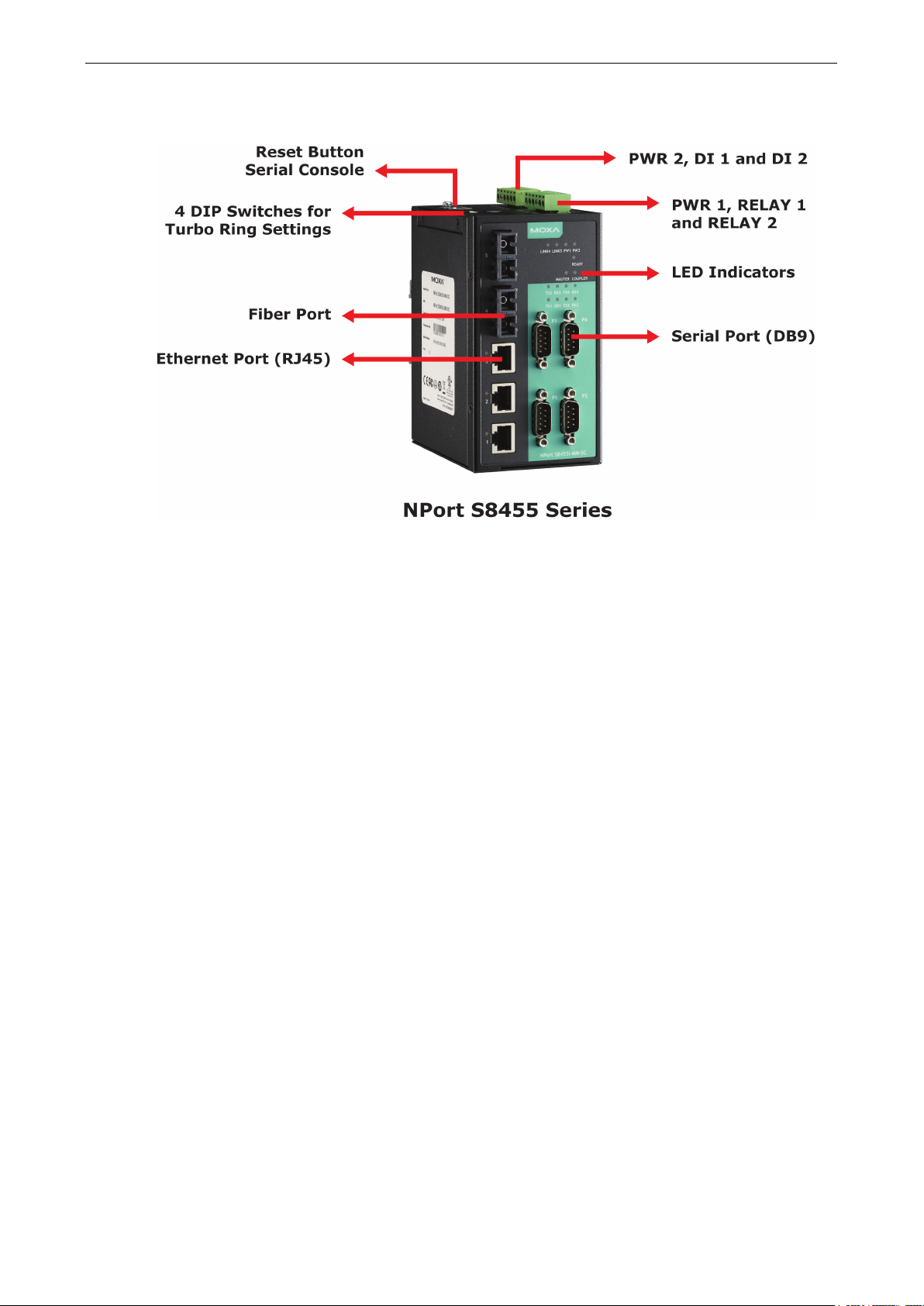
NPort S8455 Series ..................................................................................................................... 2-3
NPort S8458 Series ..................................................................................................................... 2-4
Connecting the Hardware..................................................................................................................... 2-4
Wiring Requirements ................................................................................................................... 2-5
Connecting the Power .................................................................................................................. 2-5
Connecting to the Network ........................................................................................................... 2-6
Connecting to a Serial Device ....................................................................................................... 2-6
LED Indicators ............................................................................................................................ 2-6
Adjustable Pull High/low Resistors and Terminators for the RS-485 Port (NPort S8455I Series only) ...... 2-6
Wiring the Relay Contact .............................................................................................................. 2-7
Wiring the Digital Inputs .............................................................................................................. 2-8
3. Initial IP Address Configuration ........................................................................................................ 3-1
Static and Dynamic IP Addresses .......................................................................................................... 3-2
Factory Default IP Address ................................................................................................................... 3-2
Configuration Options .......................................................................................................................... 3-2
Device Search Utility .................................................................................................................... 3-2
Web Console ............................................................................................................................... 3-2
ARP ........................................................................................................................................... 3-2
SSH Console ............................................................................................................................... 3-3
Serial Console ............................................................................................................................. 3-7
4. Choosing the Serial Operation Mode ................................................................................................. 4-1
Overview ........................................................................................................................................... 4-2
Real COM Mode .................................................................................................................................. 4-2
RFC2217 Mode ................................................................................................................................... 4-3
TCP Server Mode ................................................................................................................................ 4-3
TCP Client Mode ................................................................................................................................. 4-3
UDP Mode .......................................................................................................................................... 4-4
Disabled Mode .................................................................................................................................... 4-4
5. Use Real COM Mode to Communicate with Serial Devices .................................................................. 5-1
Overview ........................................................................................................................................... 5-2
Device Search Utility ........................................................................................................................... 5-2
Installing the Device Search Utility ................................................................................................ 5-2
Find a Specific NPort on the Ethernet Network via the DSU ............................................................... 5-5
Opening Your Browser ................................................................................................................. 5-6
Configure Operation Mode to Real COM Mode.................................................................................. 5-8
NPort Windows Driver Manager ............................................................................................................ 5-9
Installing the NPort Windows Driver Manager .................................................................................. 5-9
Using NPort Windows Driver Manager .......................................................................................... 5-12
Linux Real TTY Drivers ...................................................................................................................... 5-19
Basic Procedures ....................................................................................................................... 5-19
Hardware Setup ........................................................................................................................ 5-20
Installing Linux Real TTY Driver Files ........................................................................................... 5-20
Mapping TTY Ports ..................................................................................................................... 5-20
Removing Mapped TTY Ports ....................................................................................................... 5-21
Removing Linux Driver Files ........................................................................................................ 5-21
The UNIX Fixed TTY Driver ................................................................................................................. 5-21
Installing the UNIX Driver........................................................................................................... 5-21
Configuring the UNIX Driver ....................................................................................................... 5-22
6. Basic Settings and Device Server Configuration ................................................................................ 6-1
Basic Settings .................................................................................................................................... 6-2
General Settings ......................................................................................................................... 6-2
Time Settings ............................................................................................................................. 6-3
Network Settings ......................................................................................................................... 6-4
Serial Settings .................................................................................................................................... 6-7
Operation Modes ......................................................................................................................... 6-7
Serial Parameters ...................................................................................................................... 6-22
Page 4

Serial ToS Settings .................................................................................................................... 6-24
7. Switch Featured Functions ................................................................................................................ 7-1
Ethernet Settings ................................................................................................................................ 7-2
Port Settings ............................................................................................................................... 7-2
Port Trunking .............................................................................................................................. 7-3
Communication Redundancy ......................................................................................................... 7-5
STP/RSTP ........................................................................................................................................ 7-15
The STP/RSTP Concept .............................................................................................................. 7-15
Configuring STP/RSTP ................................................................................................................ 7-19
Configuration Limits of STP/RSTP ................................................................................................ 7-20
Bandwidth Management .................................................................................................................... 7-21
Using Bandwidth Management .................................................................................................... 7-21
Configuring Bandwidth Management ............................................................................................ 7-21
Line Swap Fast Recovery ................................................................................................................... 7-21
Using Line-Swap-Fast-Recovery .................................................................................................. 7-21
Configuring Line-Swap Fast Recovery .......................................................................................... 7-22
Ethernet Advanced Settings ............................................................................................................... 7-22
Ethernet Traffic Prioritization ...................................................................................................... 7-22
The Traffic Prioritization Concept ................................................................................................. 7-23
Configuring Ethernet Traffic Prioritization ..................................................................................... 7-24
Virtual LAN ...................................................................................................................................... 7-27
Using Virtual LAN ...................................................................................................................... 7-27
The Virtual LAN (VLAN) Concept .................................................................................................. 7-27
Configuring Virtual LAN .............................................................................................................. 7-31
Multicast Filtering ............................................................................................................................. 7-33
Using Multicast Filtering ............................................................................................................. 7-33
The Concept of Multicast Filtering ................................................................................................ 7-33
Configuring IGMP Snooping ........................................................................................................ 7-35
IGMP Snooping Settings ............................................................................................................. 7-36
Configuring GMRP...................................................................................................................... 7-38
Set Device IP ................................................................................................................................... 7-38
Using Set Device IP ................................................................................................................... 7-38
Configuring Set Device IP ........................................................................................................... 7-39
System Management ......................................................................................................................... 7-40
Misc. Network Settings ............................................................................................................... 7-40
SysLog Server .................................................................................................................................. 7-41
Using Syslog ............................................................................................................................. 7-41
Local User Database .................................................................................................................. 7-43
Port Access Control ........................................................................................................................... 7-43
Configuring Static Port Lock ........................................................................................................ 7-45
Configuring IEEE 802.1X ............................................................................................................ 7-46
Auto Warning Settings ............................................................................................................... 7-47
Configuring E-Mail Alert ..................................................................................................................... 7-47
Configuring SNMP ............................................................................................................................. 7-49
SNMP Read/Write Settings .......................................................................................................... 7-50
E-mail Event Settings ................................................................................................................ 7-51
SNMP Trap ............................................................................................................................... 7-53
Relay Alarm Settings ................................................................................................................. 7-54
System Log Settings .................................................................................................................. 7-55
Maintenance .................................................................................................................................... 7-57
Console Settings ....................................................................................................................... 7-57
Ping ......................................................................................................................................... 7-57
Update System Files from Local PC .............................................................................................. 7-58
Load Factory Default .................................................................................................................. 7-60
Change Password ...................................................................................................................... 7-61
Mirror Port Settings ................................................................................................................... 7-61
TFTP Settings............................................................................................................................ 7-62
DIP Switch Settings ................................................................................................................... 7-63
System Monitoring ............................................................................................................................ 7-65
Serial Status ............................................................................................................................. 7-65
System Status .......................................................................................................................... 7-67
Ethernet Status ......................................................................................................................... 7-68
Restart ............................................................................................................................................ 7-73
Restart System ......................................................................................................................... 7-73
Restart Serial Port ..................................................................................................................... 7-74
A. Pinouts and Cable Wiring .................................................................................................................. A-1
Port Pinout Diagrams .......................................................................................................................... A-2
Ethernet Port Pinouts ................................................................................................................... A-2
Serial Port Pinouts ....................................................................................................................... A-2
Cable Wiring Diagrams ........................................................................................................................ A-3
Ethernet Cables........................................................................................................................... A-3
Page 5

B. Well-Known Port Numbers ................................................................................................................ B-1
C. SNMP Agents with MIB II & RS-232 Like Groups .............................................................................. C-1
D. Switch MIB Groups ............................................................................................................................ D-1
E. Compliance Note ............................................................................................................................... E-1
Page 6

1
1. Introduction
The Moxa NPort S8000 is an advanced industrial serial device server integrated with a fully managed redundant
Ethernet switch, which enables easy network operation for your serial devices and connects Ethernet-enabled
devices in industrial field applications.
The NPort S8000 Series includes seven models:
• NPort S8455I
Combination switch / device server with 4 RS-232/422/485 ports, 5 10/100M Ethernet ports, RJ45
connector, 12–48 VDC, 0 to 60°C operating temperature
• NPort S8455I-T
Combination switch / device server with 4 RS-232/422/485 ports, 5 10/100M Ethernet ports, RJ45
connector, 12–48 VDC, -40 to 75°C operating temperature
• NPort S8455I-MM-SC
Combination switch / device server with 4 RS-232/422/485 ports, 3 10/100M Ethernet ports, 2 100M
multimode fiber ports, SC connector, 12–48 VDC, 0 to 60°C operating temperature
• NPort S8455I-MM-SC-T
Combination switch / device server with 4 RS-232/422/485 ports, 3 10/100M Ethernet ports, 2 100M
multimode fiber ports, SC connector, 12–48 VDC, -40 to 75°C operating temperature
• NPort S8455I-SS-SC
Combination switch / device server with 4 RS-232/422/485 ports, 3 10/100M Ethernet ports, 2 100M
single-mode fiber ports, SC connector, 12–48 VDC, 0 to 60°C operating temperature
• NPort S8455I-SS-SC-T
Combination switch / device server with 4 RS-232/422/485 ports, 3 10/100M Ethernet ports, 2 100M
single-mode fiber ports, SC connector, 12–48 VDC, -40 to 75°C operating temperature
• NPort S8458-4S-SC-T
4 RS-232/422/485 ports, 4 10/100M Ethernet ports, 4 100M single-mode fiber ports with SC connector,
combo switch serial device server, 12-48 VDC, -40 to 85°C operating temperature
The following topics are covered in this chapter:
Overview
Industrial Communications and Automation
Industrial vs. Commercial
Informative vs. Passive
Package Checklist
Product Features
Page 7

NPort S8000 Series Introduction
1-2
Overview
The NPort S8000 is an industrial device server that integrates a managed Ethernet switch with a fully functional
serial device server. The NPort S8000 device servers are designed to make your industrial serial devices
instantly Internet-ready.
The NPort S8458 offers four fiber Ethernet ports, four Ethernet ports, and four RS-232/422/485 serial ports in
a single device. Its design not only saves cabinet space and reduces power consumption, but also saves money
since you don’t need to purchase separate switches and serial device servers.
The compact size of the NPort S8000 device servers makes them the ideal choice for connecting
RS-232/422/485 serial devices, such as PLCs, meters, and sensors, to an IP-based Ethernet LAN, making it
possible for your software to access serial devices anywhere over a LAN or the Internet.
The NPort S8000 is a fully equipped managed Ethernet Switch with a suite of useful maintenance and
monitoring functions, and it is designed to provide smooth and reliable operation in harsh industrial
environments. It is ideal for keeping automation systems running continuously, sending status reports to help
prevent system damage and losses, and managing your industrial Ethernet networks and serial devices.
Industrial Communications and Automation
As the world’s networking and information technology becomes more complex, Ethernet has become the major
communications interface in many industrial communications and automation applications. In fact, a whole
new industry has sprung up to provide Ethernet products that comply with the requirements of demanding
industrial applications.
Industrial vs. Commercial
Users have found that when transplanting Ethernet from comfortable office environments to harsh and less
predictable industrial environments, commercial Ethernet equipment available in today’s market simply cannot
meet the high-reliability requirements demanded by industrial applications. This means that more robust
networking equipment, commonly referred to as industrial Ethernet equipment, is required for these
applications.
Informative vs. Passive
Since industrial Ethernet devices are often located at the endpoints of a system, such devices cannot always
know what’s happening elsewhere on the network. This means that industrial Ethernet communication
equipment that connects these devices must provide system administrators with real-time alarm messages.
Package Checklist
The Moxa NPort S8000 Series products are shipped with the following items:
Standard Accessories
• 1 NPort S8000 serial device server
• NPort Document & Software CD
• NPort S8000 Series Quick Installation Guide
• Product warranty statement
• RJ45-to-DB9 console port cable
Optional Accessories
• Wall-mounting kit
NOTE: Notify your sales representative if any of the above items is missing or damaged.
Page 8

NPort S8000 Series Introduction
1-3
Product Features
The NPort S8000 Series products enjoy the following features:
• Make your serial devices Internet ready
• Versatile socket operation modes, including TCP Server, TCP Client, and UDP
• Easy-to-use Windows Utility for mass installation
• Supports 10/100 Mbps Ethernet—auto detectable
• Supports SNMP MIB-II for network management
• Configuration auto-restore by LLDP (Link Layer Discovery Protocol)
• Configurable serial data transmission priority
• Multiport managed Ethernet switch
• Ethernet redundancy by Turbo Ring (recovery time < 20 ms), RSTP/STP (IEEE 802.1w/D)
• QoS, IGMP snooping/GMRP, VLAN, LACP, SNMPv1/v2c/v3, RMON supported
• 4 serial ports device server, support RS-232/422/RS-485
• 2k VDC isolation protection for serial port (the NPort S8455I Series only)
• Surge protection for serial/power/Ethernet
• Adjustable pull high/low resistor and terminators for the RS-485 port (the NPort S8455I Series only)
• 2- or 4-wire RS-485 with patented ADDC™ (Automatic Data Direction Control)
Page 9

2
2. Getting Started
This chapter details the installation of the NPort S8000 series device servers. Note that the manual uses the
NPort S8455 Series as an example to illustrate the functionality of the NPort S8000 Series in chapters 2, 3, 4,
6 and 7.
The following topics are covered in this chapter:
Panel Layout
Dimensions
NPort S8455 Series
NPort S8458 Series
Connecting the Hardware
Wiring Requirements
Connecting the Power
Connecting to the Network
Connecting to a Serial Device
LED Indicators
Adjustable Pull High/low Resistors and Terminators for the RS-485 Port (NPort S8455I Series only)
Wiring the Relay Contact
Wiring the Digital Inputs
Page 10
NPort S8000 Series Getting Started
2-2
Panel Layout
Page 11
NPort S8000 Series Getting Started
2-3
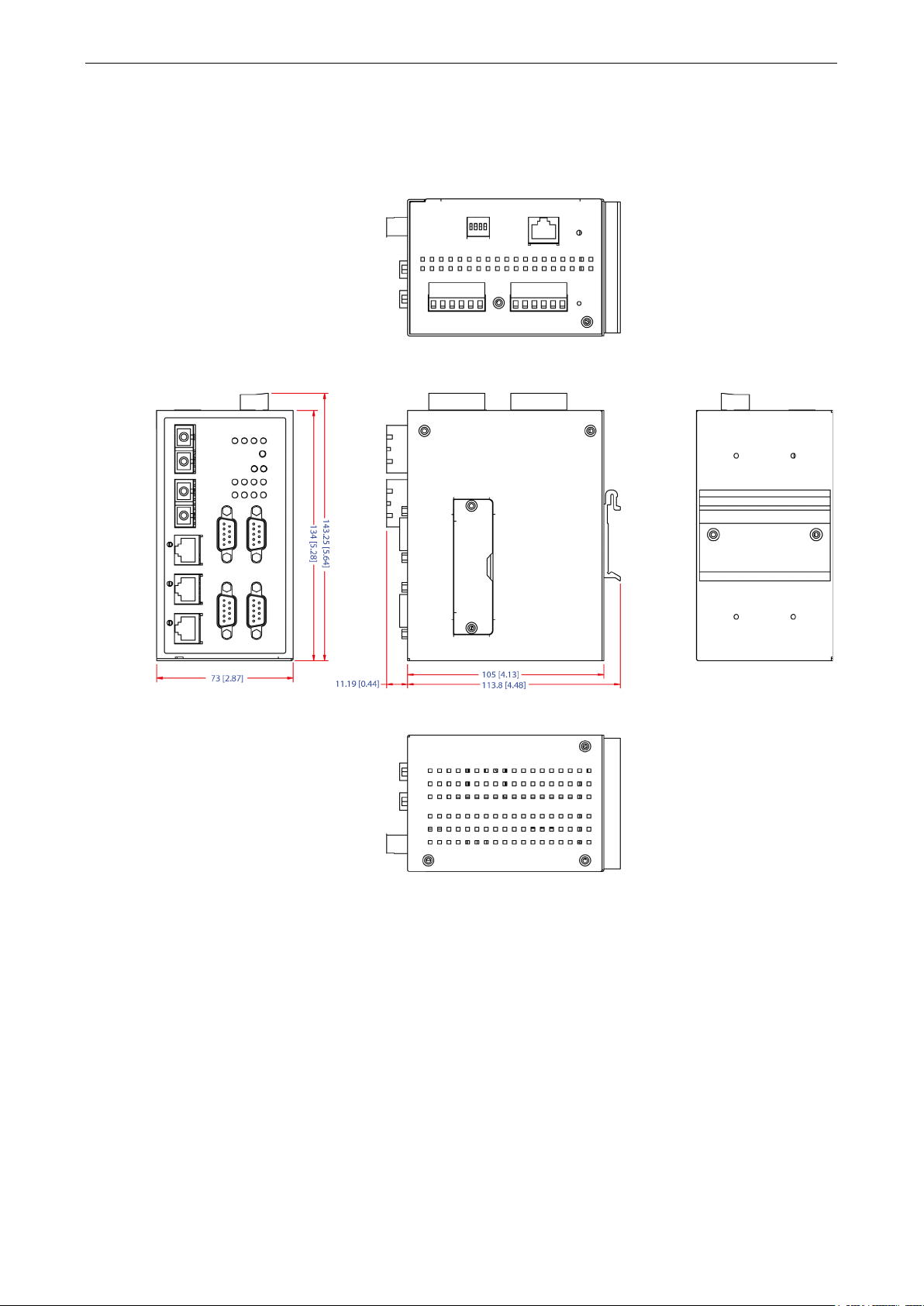
Dimensions
NPort S8455 Series
Page 12
NPort S8000 Series Getting Started
2-4
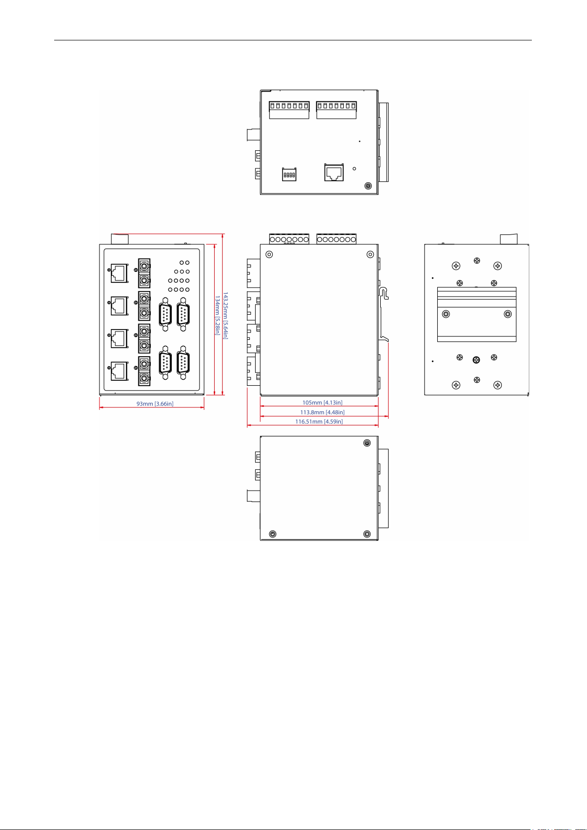
NPort S8458 Series
Connecting the Hardware
This section describes how to connect the NPort S8000 to serial devices for initial testing purposes. We cover
Wiring Requirements, Connecting the Power, Grounding the NPort S8000, Connecting to the
Network, Connecting to a Serial Device, and LED Indicators.
Page 13
NPort S8000 Series Getting Started
2-5
ATTENTION
Safety First!
Be sure to disconnect the power cord before installing and/or wiring your NPort S8000.
Wiring Caution!
Calculate the maximum possible current in each power wire and com
dictating the maximum current allowable for each wire size.
If the current goes above the
, the wiring could overheat, causing serious damage to your
equipment.
Temperature Caution!
Please take care whe
generate heat; consequently, the casing may be too hot to touch.
Wiring Requirements
You should heed the following:
• Use separate paths to route wiring for power and devices. If power wiring and device wiring paths must
cross, make sure the wires are perpendicular at the intersection point.
NOTE: Do not run signal or communication wiring and power wiring in the same wire conduit. To avoid
interference, wires with different signal characteristics should be routed separately.
• You can use the type of signal transmitted through a wire to determine which wires should be kept separate.
The rule of thumb is that wiring that shares similar electrical characteristics can be bundled together.
• Keep input wiring and output wiring separate.
• Where necessary, it is strongly advised that you label wiring to all devices in the system.
mon wire. Observe all electrical codes
allowed maximum
n handling the NPort S8000. When plugged in, the NPort S8000’s internal components
Connecting the Power
Connect the 12-48 VDC power line with the NPort S8000’s terminal block. If the power is properly supplied, the
“Ready” LED will show a solid red color until the system is ready, at which time the “Ready” LED will change to
a green color.
Take the following steps to wire the redundant power inputs:
1. Insert the negative/positive DC wires into the V-/V+ terminals.
2. To keep the DC wires from pulling loose, use a small flat-blade screwdriver to tighten the wire-clamp screws
on the front of the terminal block connector.
3. Insert the plastic terminal block connector prongs into the terminal block receptor, which is located on the
EDS’s top panel.
Page 14

NPort S8000 Series Getting Started
2-6
When the NPort is the Ring Master of this Turbo Ring and the Turbo Ring
Serial Port RX
Yellow
The serial port is receiving data.
IP conflict, or the DHCP or BOOTP server did
Connecting to the Network
Connect one end of the Ethernet cable to the NPort S8000’s 10/100M Ethernet port and the other end of the
cable to the Ethernet network. If the cable is properly connected, the NPort S8000 will indicate a valid
connection to the Ethernet in the following ways:
• The Ethernet LED maintains a solid green color when connected to a 100 Mbps Ethernet network.
• The Ethernet LED will flash when Ethernet packets are being transmitted or received.
Connecting to a Serial Device
Connect the serial data cable between the NPort S8000 and the serial device.
LED Indicators
The LED indicators of the NPort S8000 Series are described in the following table.
Type Color Meaning
PWR 1 Green Power 1 input
PWR 2 Green Power 2 input
LINK (FX)
LINK
Master
Coupler Green When the NPort enables the coupling function to form a backup path
Serial Port TX Green The serial port is transmitting data.
Green FX port 100 Mbps is active
Blinking Data is being transmitted/received at 100 Mbps
Green 100 Mbps Ethernet connection
Blinking 10 Mbps Ethernet connection
Green When the NPort is the Master of this Turbo Ring
Yellow
is broken
Steady On: Power is on, and NPort is booting up.
Red
Ready
Green
Off Power is off, or power error condition exists.
Blinking: Indicates an LAN-
not respond properly.
Steady On: Power is on, and NPort is functioning normally.
Blinking: The device server has been located by Administrator’s Location
function.
Adjustable Pull High/low Resistors and Terminators for the
RS-485 Port (NPort S8455I Series only)
In some critical environments, you may need to add termination resistors to prevent the reflection of serial
signals. When using termination resistors, it is important to set the pull high/low resistors correctly so that the
electrical signal is not corrupted. Since there is no resistor value that works for every environment, DIP
switches are used to set the pull high/low resistor values for each RS-485 port.
To set the pull high/low resistors to 150 KΩ, make sure both of the assigned DIP switches are in the OFF
position. This is the default setting.
To set the pull high/low resistors to 1 KΩ, make sure both of the assigned DIP switches are in the ON
position.
Page 15
NPort S8000 Series Getting Started
2-7
ATTENTION
Do
the
effective communication distance.
The fault circuit will open if
and the
If none of these three conditions
met, the fault circuit will
remain
Pull High Pull Low Terminator Terminator Terminator
ON 1 KΩ 1 KΩ 120 Ω 100 Ω 55 Ω
Default
not set the resistors to 1 KΩ. When using RS-232. Doing so will degrade the RS-232 signals and reduce
SW
OFF 150 KΩ 150 KΩ – – –
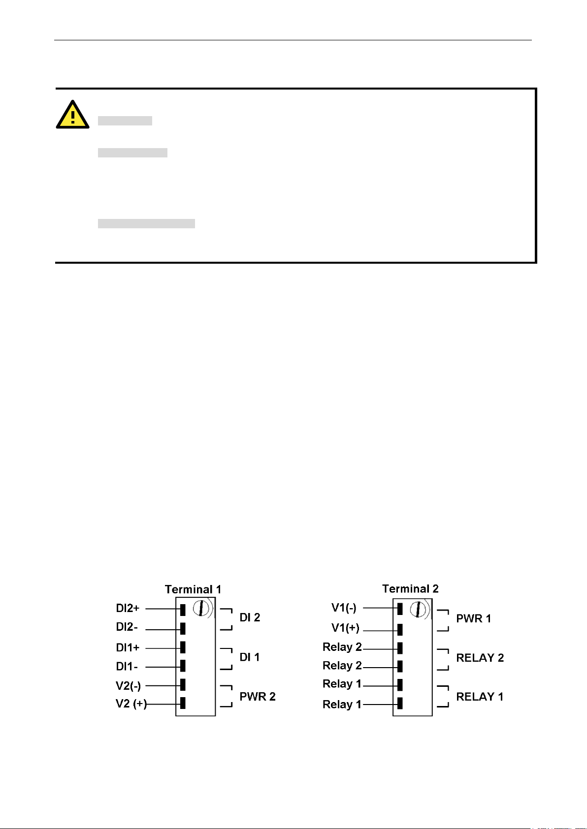
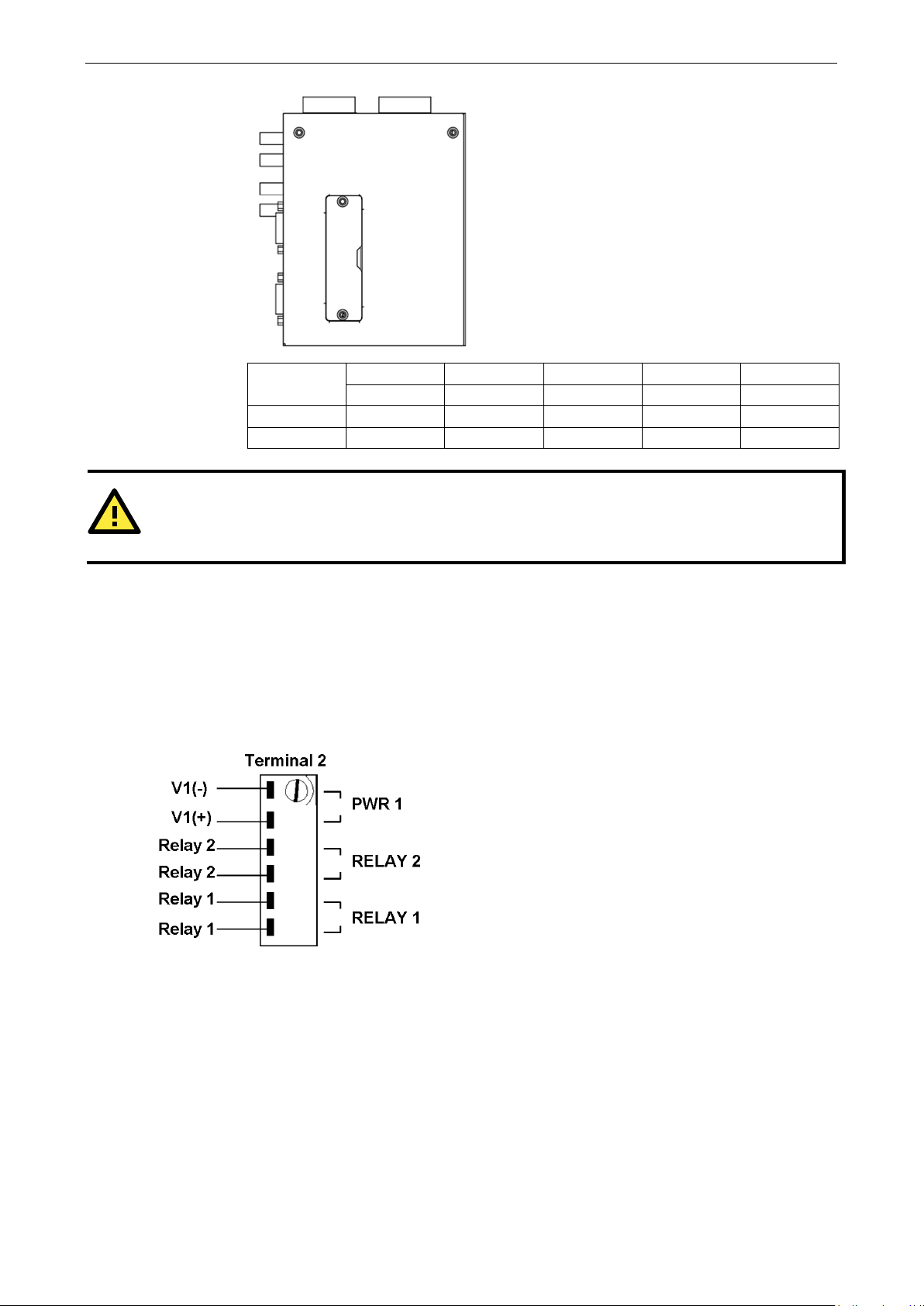
Wiring the Relay Contact
The NPort 8455I Series has two sets of relay output: relay 1 and relay 2. Each relay contact consists of two
contacts of the terminal block on the NPort 8455I’s top panel. Refer to the next section for detailed instructions
on how to connect the wires to the terminal block connector and how to attach the terminal block connector to
the terminal block receptor. The two contacts used to connect the relay contacts work as follow (illustrated
below):
1 2 3 4 3 & 4
A relay warning event is triggered,
OR
The NPort S8000 is the Master of this Turbo Ring,
Turbo Ring is broken,
OR
Start-up failure.
are
closed.
Page 16
NPort S8000 Series Getting Started
2-8
Take the following steps to wire the digital inputs:
blade
clamp screws on the front of the
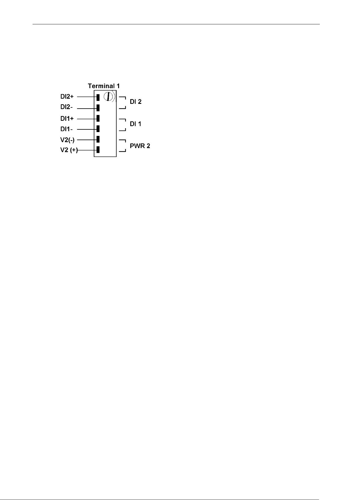
Wiring the Digital Inputs
The NPort 8455I unit has two sets of digital inputs, DI 1 and DI 2. Each DI consists of two contacts of the 6-pin
terminal block connector on the NPort 8455I’s top panel. The remaining contacts are used for the NPort 8455I’s
two DC inputs. The top and front views of one of the terminal block connectors are shown below.
Insert the negative (ground)/positive DI wires into the ┴/I1
terminals.
To keep the DI wires from pulling loose, use a small flat-
screwdriver to tighten the wire-
terminal block connector.
Insert the plastic terminal block connector prongs into the
terminal block receptor, which is located on the NPort 8455I’s
top panel.
Page 17

3
3. Initial IP Address Configuration
When setting up the NPort S8000 for the first time, the first thing you should do is configure its IP address. This
chapter introduces the different methods that can be used.
The following topics are covered in this chapter:
Static and Dynamic IP Addresses
Factory Default IP Address
Configuration Options
Device Search Utility
Web Console
ARP
SSH Console
Serial Console
Page 18

NPort S8000 Series Initial IP Address Configuration
3-2
ATTENTION
Consult your network administrator on how to reserve a
IP
mapping table when using a DHCP server or BOOTP server. For most applications, you should assign a fixed IP
address to your NPort S8000.
Static and Dynamic IP Addresses
Determine whether your NPort S8000 needs to use a static IP or dynamic IP address (either DHCP or BOOTP
application).
• If your NPort S8000 is used in a static IP environment, you will assign a specific IP address using one
of the tools described in this chapter.
• If your NPort S8000 is used in a dynamic IP environment, the IP address will be assigned
automatically over the network. In this case, set the IP configuration mode to DHCP, BOOTP.
fixed IP address for your NPort S8000 in the MAC-
Factory Default IP Address
The NPort S8000 is configured with the following default private IP address:
192.168.127.254
Note that IP addresses that begin with “192.168” are referred to as private IP addresses. Devices configured
with a private IP address are not directly accessible from a public network. For example, you would not be able
to ping a device with a private IP address from an outside Internet connection. If your application requires
sending data over a public network, such as the Internet, your NPort S8000 will need a valid public IP address,
which can be leased from a local ISP.
Configuration Options
Device Search Utility
Web Console
ARP
You may configure your NPort S8000 with the bundled Device Search Utility (DSU) for Windows platform. Note
that you will be asked to enter the username and password to access the NPort S8000 device. The default
username is admin and the default password is moxa. Please refer to Chapter 5, “Use Real COM Mode to
Communicate with Serial Devices”, for details on how to install and use the DSU.
You may configure your NPort S8000 using a standard web browser. Note that you will be asked to enter the
username and password to access the NPort S8000 device. The default username is admin and the default
password is moxa. Please refer to Chapter 6, “Basic Settings and Device Server Configuration”, for details on
how to access and use the NPort S8000 web console.
You may use the Address Resolution Protocol (ARP) command to set up an IP address for your NPort S8000.
The ARP command tells your computer to associate the NPort S8000’s MAC address with an IP address.
Afterwards, use Telnet to access the NPort S8000 and its IP address will be reconfigured.
Page 19
NPort S8000 Series Initial IP Address Configuration
3-3
ATTENTION
In order to use the ARP setup method, both your computer and
same LAN. Alternatively, you may use a crossover Ethernet cable to connect the NPort S8000 directly to your
computer’s Ethernet card. Before executing the ARP command, your NPort S8000 must be configured with the
factory default IP address (192.168.127.254), and your computer and the NPort S8000 must be on the same
subnet.
To use ARP to configure the IP address, complete the following:
1. Obtain a valid IP address for your NPort S8000 from your network administrator.
2. Obtain your NPort S8000’s MAC address from the label on the bottom panel.
3. Execute the arp -s command from your computer’s MS-DOS prompt (for Windows 7 or newer OS, please
ensure you have the administrator authority to execute the MS-DOS prompt) as follows:
arp -s <IP address> <MAC address>
For example,
C:\> arp -s 192.168.200.100 00-90-E8-04-00-11
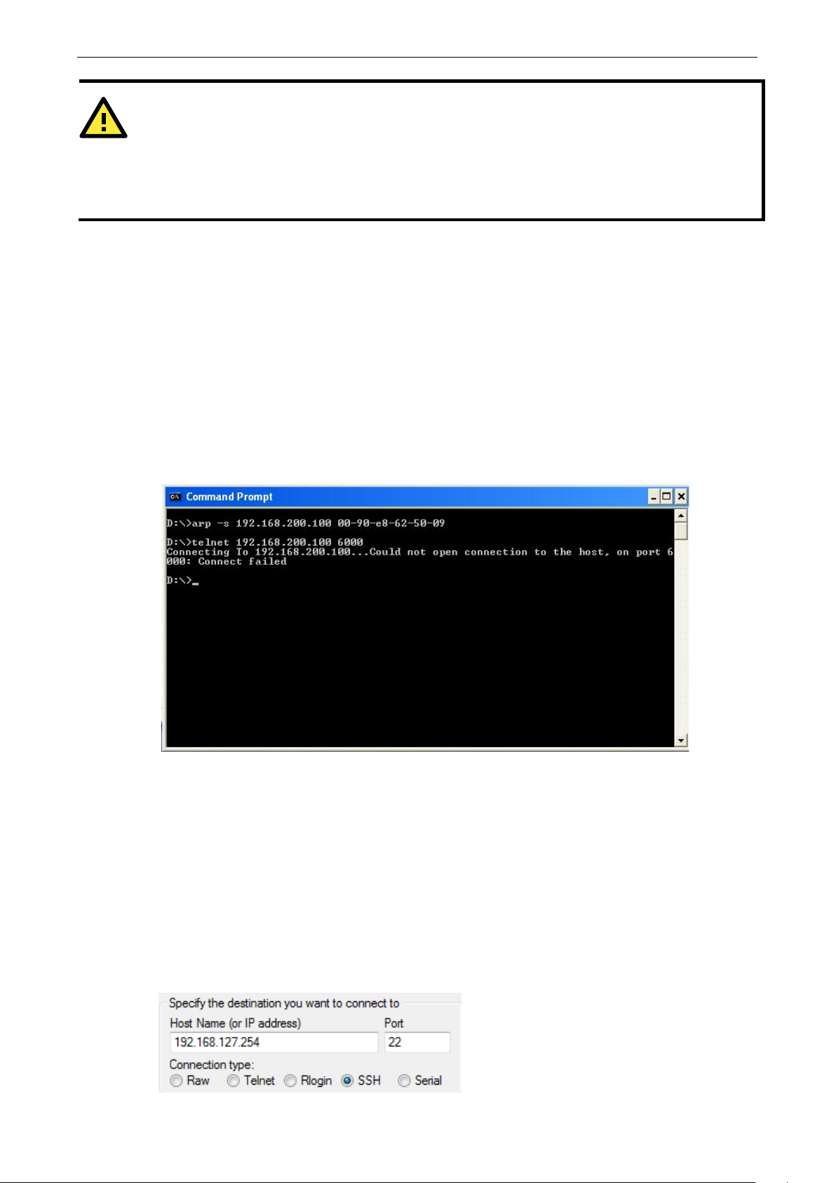
4. Next, execute a special Telnet command by entering the following exactly:
telnet 192.168.200.100 6000
When you enter this command, a Connect failed message will appear, as shown below.
the NPort S8000 must be connected to the
5. After the NPort S8000 reboots, its IP address will be assigned to the new address, and you can reconnect
using Telnet to verify that the update was successful.
SSH Console
Depending on how your computer and network are configured, you may find it convenient to use network
access to set up your NPort S8000’s IP address. This can be done using Telnet/SSH. The instructions below will
be introduced by using SSH, which offers security mechanisms that protect users against any malicious
behavior.
1. It's easy to find SSH client software on the Internet. Please download, install, and execute it and input the
destination NPort's IP and the TCP port to accept the SSH session.
Page 20
NPort S8000 Series Initial IP Address Configuration
3-4
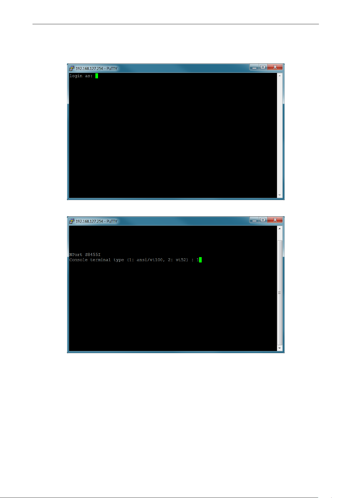
2. The console terminal type selection is displayed as shown. Enter the username and password to log in to the
SSH console. The default username and password are admin and moxa, respectively.
3. Enter 1 for ansi/vt100 and press ENTER to continue.
Page 21
NPort S8000 Series Initial IP Address Configuration
3-5
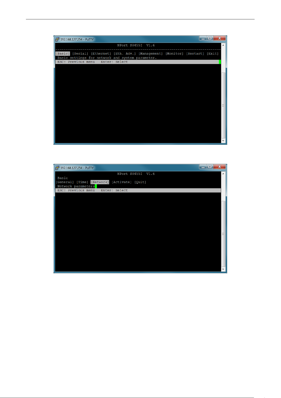
4. Press B, or use the arrow keys to select Basic and then press ENTER to configure Basic settings.
5. Press N, or use the arrow keys to select Network and then press ENTER to configure Network
parameters.
Page 22
NPort S8000 Series Initial IP Address Configuration
3-6
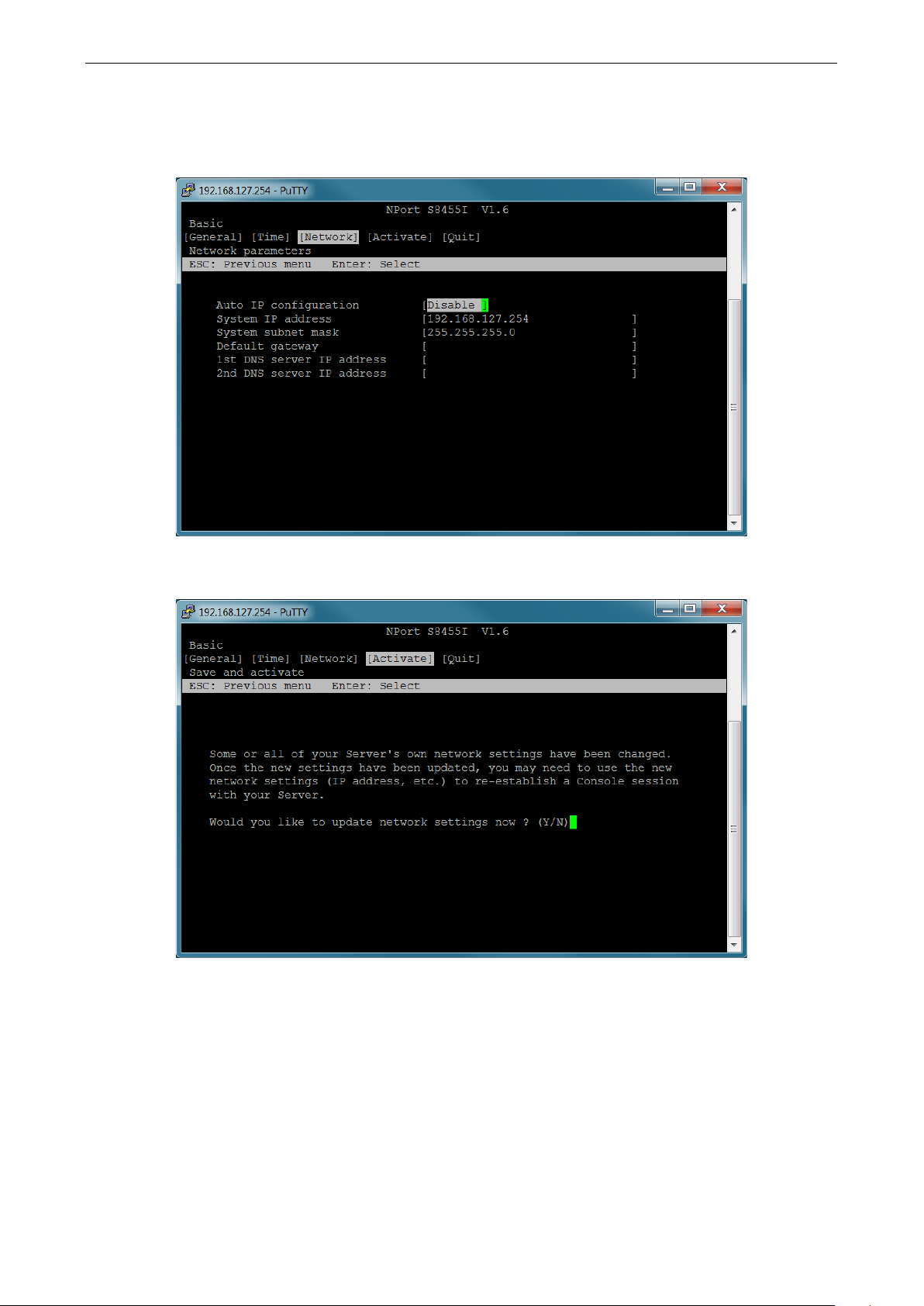
6. Use the arrow keys to move the cursor to System IP address. Use the Delete, Backspace, or Space key
to erase the current IP address, and then type in the new IP address and press Enter. If you are using a
dynamic IP configuration (BOOTP or DHCP), you will need to go to the Auto IP configuration field and press
Enter to select the appropriate configuration.
7. Press Esc to return to the previous page. Select Activate and press Y to confirm the modification and
activate the new settings.
Page 23
NPort S8000 Series Initial IP Address Configuration
3-7
ATTENTION
The
Serial Console
The NPort S8000 supports configuration through the serial console, which is the same as the Telnet console but
accessed through the RS-232 console port rather than through the network. Once you have entered the serial
console, the configuration options and instructions are the same as if you were using the Telnet console.
The following instructions and screenshots show how to enter the serial console using PComm Terminal
Emulator, which is available free of charge as part of the PComm Lite suite. You may use a different terminal
emulator utility, although your actual screens and procedures may vary slightly from the following instructions.
1. Use a serial cable to connect the NPort S8000’s serial console port to your computer’s male RS-232 serial
port.
NPort S8000 has a dedicated serial console port.
2. From the Windows desktop select Start All Programs PComm Lite Terminal Emulator.
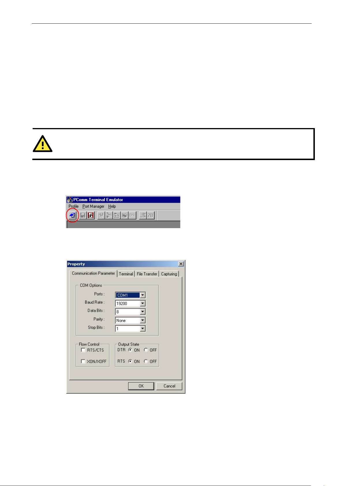
3. The PComm Terminal Emulator window should appear. From the Port Manager menu, select Open, or
simply click the Open icon as shown below:
4. The Property window opens automatically. Select the Communication Parameter tab, then select the
appropriate COM port for the connection (COM1 in this example). Configure the parameters for 19200, 8,
N, 1 (19200 for Baud Rate, 8 for Data Bits, None for Parity, and 1 for Stop Bits).
5. From the Property window’s Terminal page, select ANSI or VT100 for Terminal Type and click OK.
The NPort S8000 will then automatically switch from data mode to console mode.
Page 24
NPort S8000 Series Initial IP Address Configuration
3-8
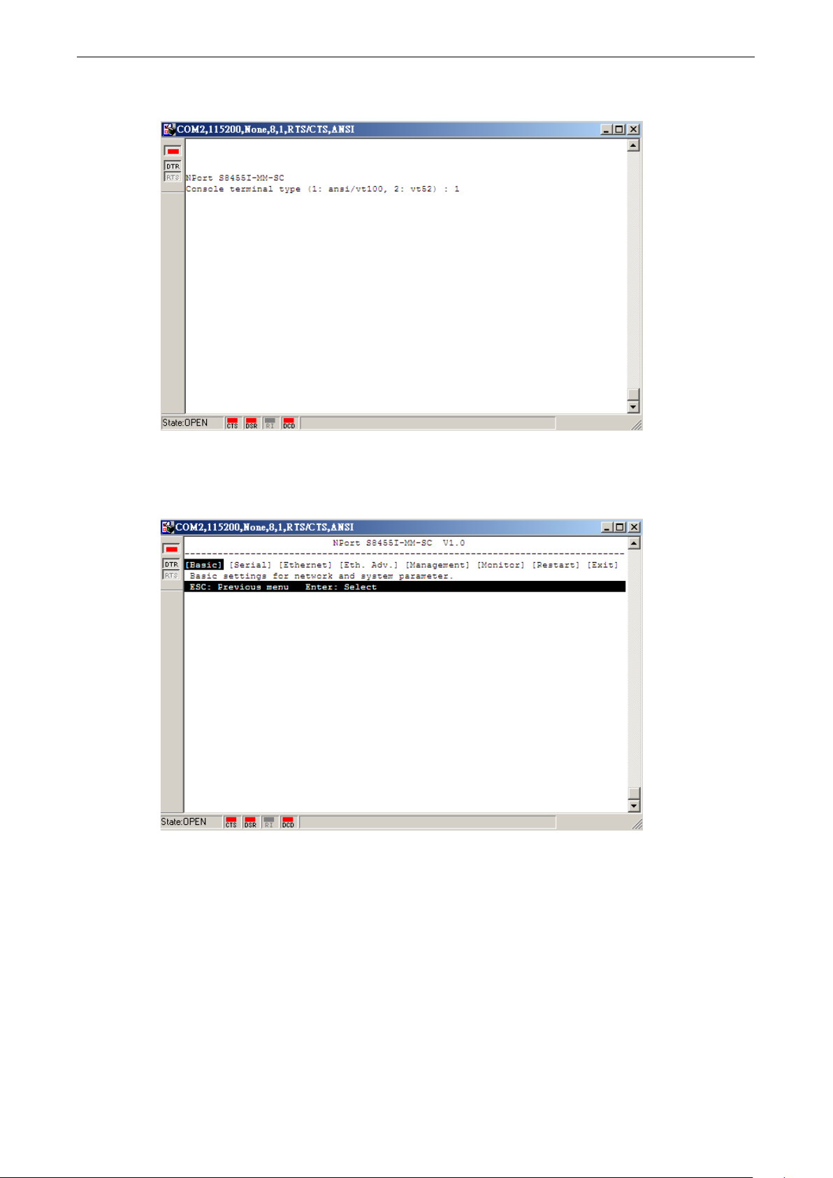
6. After you enter the password, or if password protection was not enabled, you will be prompted to select the
terminal mode. Press 1 for ansi/vt100 and then press ENTER.
7. Enter the username and password to login to the console. The default username and password are admin
and moxa, respectively. The main menu should come up. Once you are in the console, you may configure
the IP address through the Network menu item, just as with the Telnet console. Please refer to steps 4 to
8 in the Telnet Console section to complete the initial IP configuration.
Page 25

4
4. Choosing the Serial Operation Mode
In this chapter, we describe the various serial operation modes of the NPort S8000. The options include an
operation mode that uses a driver installed on the host computer and operation modes that rely on TCP/IP
socket programming concepts. After choosing the proper operation mode in this chapter, refer to Chapter 6 for
detailed configuration parameter definitions.
The following topics are covered in this chapter:
Overview
Real COM Mode
RFC2217 Mode
TCP Server Mode
TCP Client Mode
UDP Mode
Disabled Mode
Page 26
NPort S8000 Series Choosing the Serial Operation Mode
4-2
The
work with Windows 9x/NT/2000/XP/2003/Vista/2008
8.1/10
systems, and also TTY drivers for Linux
and Unix
connection between
the IP port of the NPort’s serial port to a local COM/TTY port
on the host computer. This operation mode also supports up
to 8 simultaneous connections, so that multiple hosts can
collect data from the same serial device at the same time.
ATTENTION
Real COM
with
your NPort controls
Modify the
Overview
The device server function of the NPort S8000 enables network operation of traditional RS-232/422/485
devices, in which a device server is a tiny computer equipped with a CPU, real-time OS, and TCP/IP protocols
that can bi-directionally translate data between the serial and Ethernet formats. Your computer can access,
manage, and configure remote facilities and equipment over the Internet from anywhere in the world.
Traditional SCADA and data collection systems rely on serial ports (RS-232/422/485) to collect data from
various kinds of instruments. Since the NPort S8000 networks instruments equipped with an RS-232/422/485
communication port, your SCADA and data collection system will be able to access all instruments connected
to a standard TCP/IP network, regardless of whether the devices are used locally or at a remote site.
The NPort S8000 is an external IP-based network device that allows you to expand the number of serial ports
for a host computer on demand. As long as your host computer supports the TCP/IP protocol, you won’t be
limited by the host computer’s bus limitation (such as ISA or PCI), or lack of drivers for various operating
systems.
In addition to providing socket access, the NPort also comes with a Real COM/TTY driver that transmits all serial
signals intact. This means that your existing COM/TTY-based software can be preserved, without needing to
invest in additional software.
Three different socket modes are available: TCP Server, TCP Client, and UDP Server/Client. The main
difference between the TCP and UDP protocols is that TCP guarantees delivery of data by requiring the recipient
to send an acknowledgement to the sender. UDP does not require this type of verification, making it possible
to offer a speedier delivery. UDP also allows multicasting of data to groups of IP addresses.
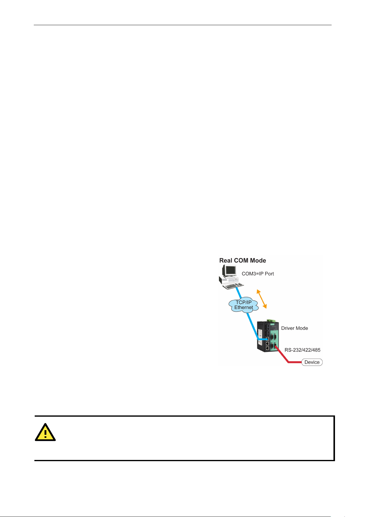
Real COM Mode
NPort S8000 comes equipped with COM drivers that
(all x86/x64)
systems. The driver establishes a transparent
the host and serial device by mapping
The important point is that Real COM Mode allows users to continue using RS-232/422/485 serial
communications software that was written for pure serial communications applications. The driver intercepts
data sent to the host’s COM port, packs it into a TCP/IP packet, and then redirects it through the host’s Ethernet
card. At the other end of the connection, the NPort accepts the Ethernet frame, unpacks the TCP/IP packet, and
then transparently sends it to the appropriate serial device attached to one of the NPort’s serial ports.
Mode allows several hosts to have access control over the same NPort. The driver that comes
the host’s access to attached serial devices by checking the host’s IP address.
Accessible IP Setting table when the legal IP address is required in your application
/7/8/
Page 27
NPort S8000 Series Choosing the Serial Operation Mode
4-3
In TCP Server mode,
NPort S8000 provides a unique IP
port address on a TCP/IP network.
passively to be contacted by the host computer, allowing the
host computer to establish a connection with and get data
from the serial device. This operation mode also supports up
to
collect data from the same serial device
As illustrated in the figure, data transmission proceeds as
follows:
In TCP Client mode,
can actively establish a
TCP connection t
data arrives.
After the data has been transferred,
automatically disconnect from the host computer
the
Refer to chapter
As illustrated in the figure, data transmission proceeds as
follows:
RFC2217 Mode
RFC-2217 mode is similar to Real COM mode. That is, a driver is used to establish a transparent connection
between a host computer and a serial device by mapping the serial port on the NPort S8000 to a local COM port
on the host computer. RFC2217 defines general COM port control options based on the Telnet protocol.
Third-party drivers supporting RFC-2217 are widely available on the Internet and can be used to implement
Virtual COM mapping to your NPort S8000 serial port(s).
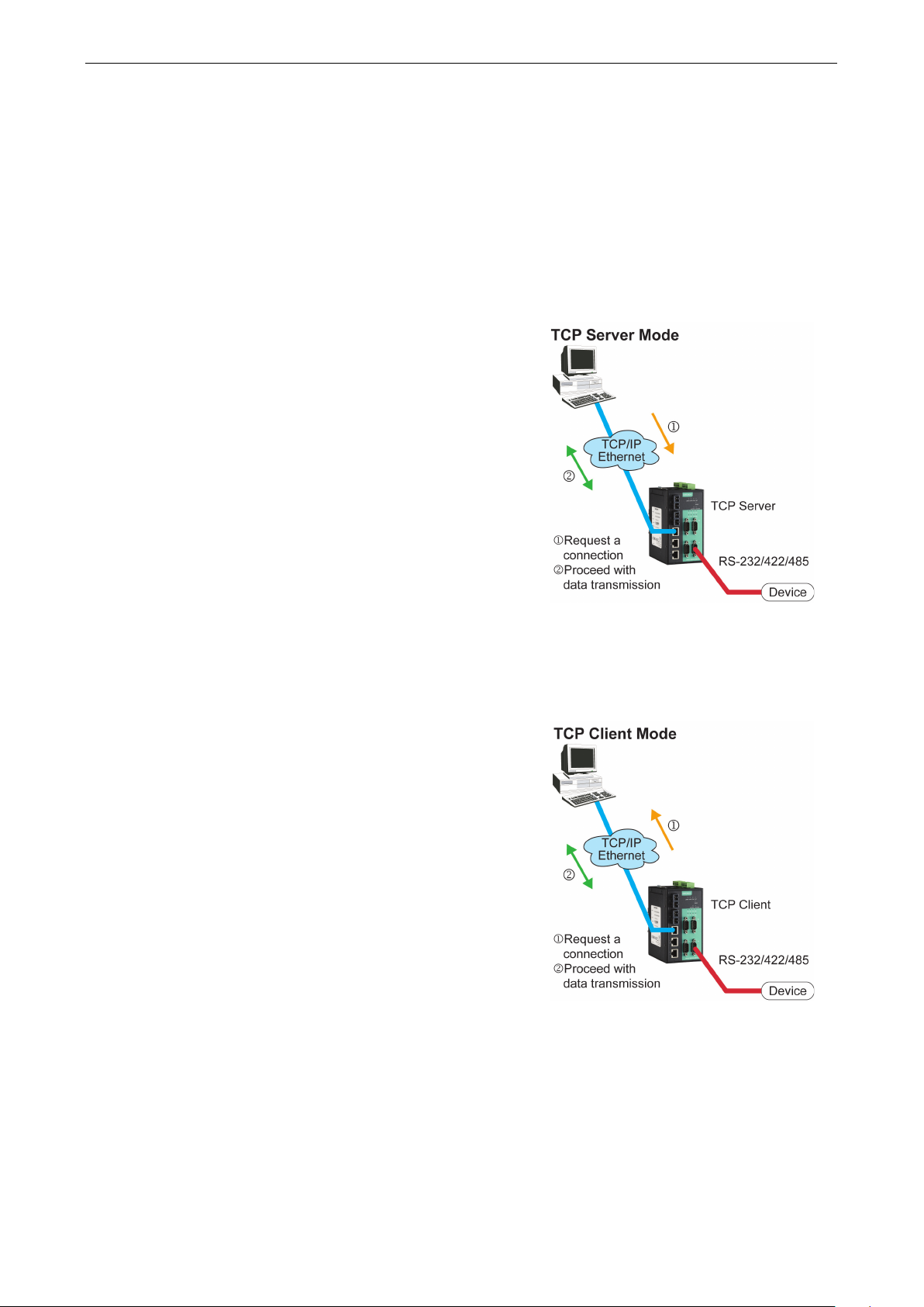
TCP Server Mode
the
The NPort S8000 waits
8 simultaneous connections, so that multiple hosts can
—at the same time.
1. The host requests a connection from the NPort
configured for TCP Server Mode.
2. Once the connection is established, data can be
transmitted in both directions—from the host to the
NPort, and from the NPort to the host.
TCP Client Mode
the NPort S8000
o a predefined host computer when serial
TCP alive check time or Inactivity time settings.
6 for more details.
1. The NPort configured for TCP Client Mode requests a
connection from the host.
2. Once the connection is established, data can be
transmitted in both directions—from the host to the
NPort, and from the NPort to the host.
the NPort S8000 can
by using
Page 28
NPort S8000 Series Choosing the Serial Operation Mode
4-4
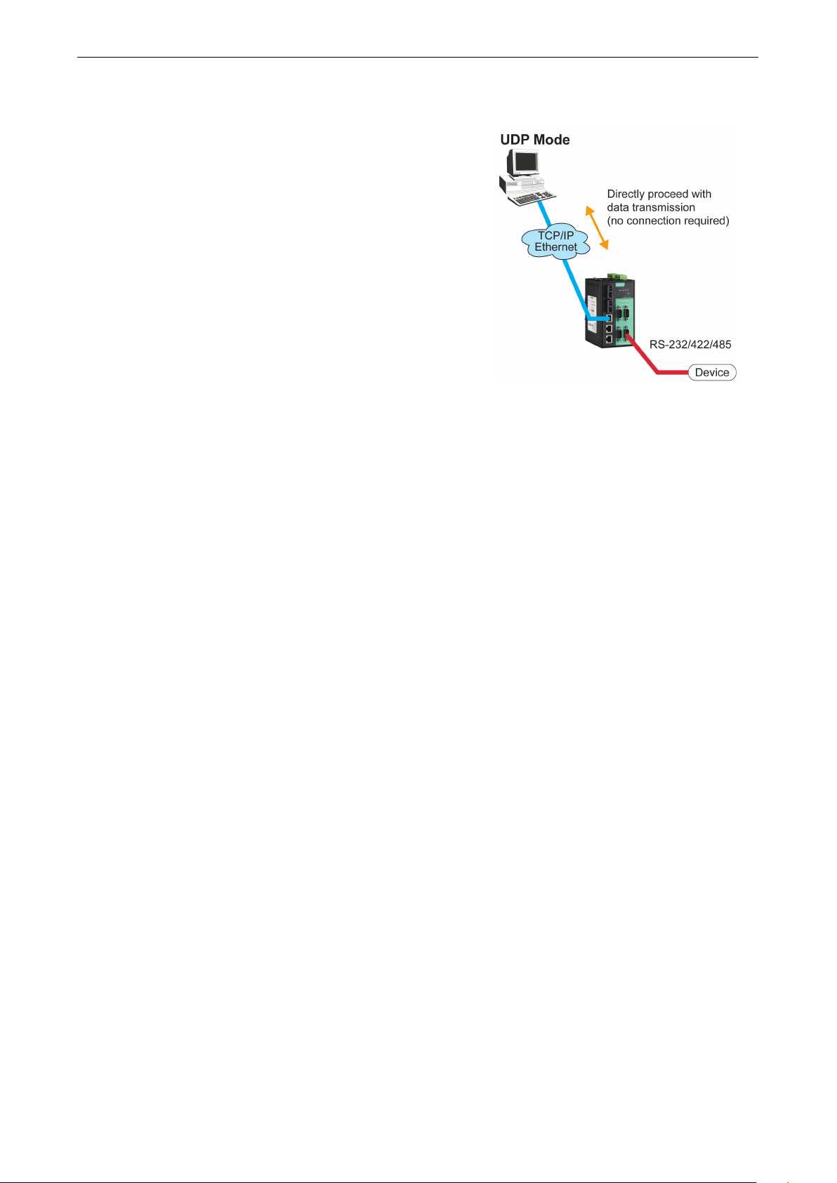
Compared to TCP communication, UDP is faster and more
efficient. In UDP mode, you can multicast data from the
serial device to multiple host computers, and the serial
device can also receive data from multiple host computers,
making this mode ideal for message display applications.
UDP Mode
Disabled Mode
When the Operation Mode for a particular port is set to Disabled, that port will be disabled.
Page 29

5
5. Use Real COM Mode to Communicate with
Serial Devices
The following topics are covered in this chapter:
Overview
Device Search Utility
Installing the Device Search Utility
Find a Specific NPort on the Ethernet Network via the DSU
Opening Your Browser
Configure Operation Mode to Real COM Mode
NPort Windows Driver Manager
Installing the NPort Windows Driver Manager
Using NPort Windows Driver Manager
Linux Real TTY Drivers
Basic Procedures
Hardware Setup
Installing Linux Real TTY Driver Files
Mapping TTY Ports
Removing Mapped TTY Ports
Removing Linux Driver Files
The UNIX Fixed TTY Driver
Installing the UNIX Driver
Configuring the UNIX Driver
Page 30

NPort S8000 Series Use Real COM Mode to Communicate with Serial Devices
5-2
Overview
The Documentation & software CD included with your NPort S8000 is designed to make the installation and
configuration procedure easy and straightforward. This auto-run CD includes the Device Search Utility (DSU)
(to broadcast search for all NPort S8000 accessible over the network and firmware upgrade), NPort driver for
Windows and Linux platforms (for COM mapping), and the NPort S8000 User’s Manual.
This chapter will instruct you on how to install the necessary software and provide the steps to mapping virtual
COM port to help user's software keep working as usual.
1. Install the Device Search Utility to find the specific NPort on the Ethernet network.
2. Log in to the Web console to configure the device to work on Real COM mode.
3. Install the NPort driver and mapping COM port.
4. The original utility can open the COM port to transmit/receive data to/from the serial device.
Device Search Utility
Installing the Device Search Utility
1. Click the INSTALL UTILITY button in the NPort Installation CD auto-run window to install the NPort Search
Utility. Once the program starts running, click Yes to proceed.
2. Click Settings when the Welcome screen opens, to proceed with the installation.
Page 31

NPort S8000 Series Use Real COM Mode to Communicate with Serial Devices
5-3
3. Click Next to install program files to the default directory, or click Browse to select an alternate location.
4. Check the checkbox if you want the DSU to create a desktop icon, or just click Next to install the program's
shortcuts in the appropriate Start Menu folder.
Page 32

NPort S8000 Series Use Real COM Mode to Communicate with Serial Devices
5-4
5. Click Next to proceed with the installation. The installer then displays a summary of the installation options.
6. Click Install to begin the installation. The setup window will report the progress of the installation. To
change the installation settings, click Back and navigate to the previous screen.
7. Click Finish to complete the installation of the NPort Search Utility.
Page 33

NPort S8000 Series Use Real COM Mode to Communicate with Serial Devices
5-5
Find a Specific NPort on the Ethernet Network via the DSU
The Broadcast Search function is used to locate all the NPort S8000 servers that are connected to the same LAN
as your computer. After locating an NPort S8000, you will be able to change its IP address.
Since the Broadcast Search function searches by MAC address and not by IP address, all NPort S8000 servers
connected to the LAN will be located, regardless of whether or not they are part of the same subnet as the host.
1. Open the DSU and then click the Search icon.
The Searching window indicates the progress of the search.
Page 34

NPort S8000 Series Use Real COM Mode to Communicate with Serial Devices
5-6
2. When the search is complete, all the NPort S8000 servers that were located will be displayed in the DSU
window.
3. To modify the configuration of the highlighted NPort S8000, click on the Console icon to open the web
console. This will take you to the web console, where you can make all configuration changes. Please refer
to Chapter 6, “Configuration with the Web Console”, for information on how to use the web console.
Opening Your Browser
1. Open your browser with the cookie function enabled. (To enable your browser for cookies, right-click on
your desktop Internet Explorer icon, select Properties, click on the Security tab, and then select the three
Enable options as shown in the figure below.)
2. After using the DSU to find a specific NPort, type the IP address to log in to the web console. If this is the
first time you configure the NPort, you may directly type the default IP address, 192.168.127.254 in the
Address input box. Use the correct IP address if it is different from the default and then press Enter.
Page 35

NPort S8000 Series Use Real COM Mode to Communicate with Serial Devices
5-7
ATTENTION
If you use other web browsers, remember to Enable the functions to allow cookies that are stored on your
computer
ATTENTION
Refer to Chapter 3, “Initial IP Address Configuration,” to see how to configure the IP address. Examples shown
in this chapter
ATTENTION
If you
by using
the
3. On the first page of the web console, type admin for the default account name and moxa for the default
password.
The NPort S8000 homepage will open. On this page, you can see a brief description of the Web Console
or allow per-session cookies. Device servers use cookies only for “password” transmission.
use the Factory Default IP address (192.168.127.254).
forgot the password, the ONLY way to start configuring the NPort is to load the factory defaults
reset button.
Page 36

NPort S8000 Series Use Real COM Mode to Communicate with Serial Devices
5-8
ATTENTION
Remember to e
button to load the factory defaults, your configuration can be easily reloaded into
NPort by using the Import
function. Refer to
for more details about using
the Export and Import functions.
ATTENTION
If your NPort application requires using password protection, you must enable the cookie function in your
browser. If
xport the configuration file when you have finished the configuration. After using the reset
Chapter 7, "Maintenance / Update System Files from Local PC",
the cookie function is disabled, you will not be allowed to enter the Web Console Screen.
Configure Operation Mode to Real COM Mode
Click on Operation Modes, located under Serial Settings, to display the serial port settings for four serial ports.
To modify the serial operation mode settings for a particular port, click on Operation Modes of the serial port
in the window on the right-hand side.
the
Page 37

NPort S8000 Series Use Real COM Mode to Communicate with Serial Devices
5-9
NPort Windows Driver Manager
Installing the NPort Windows Driver Manager
The NPort Windows Driver Manager is intended for use with NPort S8000 serial ports that are set to Real COM
mode. The software manages the installation of drivers that allow you to map unused COM ports on your PC to
serial ports on the NPort S8000. When the drivers are installed and configured, devices that are attached to
serial ports on the NPort S8000 will be treated as if they were attached to your PC’s own COM ports.
1. Click the INSTALL COM Driver button in the NPort Installation CD auto-run window to install the NPort
Windows Driver. Once the installation program starts running, click Yes to proceed.
2. Click Next when the Welcome screen opens, to proceed with the installation.
Page 38

NPort S8000 Series Use Real COM Mode to Communicate with Serial Devices
5-10
Click Next to install program files to the default directory, or click Browse to select an alternate location.
3. Click Next to install the program’s shortcuts in the appropriate Start Menu folder.
Page 39

NPort S8000 Series Use Real COM Mode to Communicate with Serial Devices
5-11
4. Click Next to proceed with the installation. The installer then displays a summary of the installation options.
5. Click Install to begin the installation. The setup window will report the progress of the installation. To
change the installation settings, click Back and navigate to the previous screen. The installer will display a
message that the software has not passed Windows Logo testing. This is shown as follows:
Click Continue Anyway to finish the installation.
Page 40

NPort S8000 Series Use Real COM Mode to Communicate with Serial Devices
5-12
6. Click Finish to complete the installation of the NPort Windows Driver Manager.
Using NPort Windows Driver Manager
After you have installed the NPort Windows Driver Manager, you can set up the NPort S8000’s serial ports as
remote COM ports for your PC host. Make sure that the serial port(s) on your NPort S8000 are set to Real COM
mode before mapping COM ports with the NPort Windows Driver Manager.
1. Go to Start NPort Windows Driver Manager NPort Windows Driver Manager to start the COM
mapping utility.
2. Click the Add icon.
Page 41

NPort S8000 Series Use Real COM Mode to Communicate with Serial Devices
5-13
3. Click Search to search for the NPort device servers. From the list that is generated, select the server to
which you will map COM ports, and then click OK.
4. Alternatively, you can select Input Manually and then manually enter the NPort IP Address, 1st Data Port,
1st Command Port, and Total Ports to which COM ports will be mapped. Click OK to proceed to the next step.
Note that the Add NPort page supports FQDN (Fully Qualified Domain Name), in which case the IP address
will be filled in automatically.
Page 42

NPort S8000 Series Use Real COM Mode to Communicate with Serial Devices
5-14
5. COM ports and their mappings will appear in blue until they are activated. Activating the COM ports saves
the information in the host system registry and makes the COM port available for use. The host computer
will not have the ability to use the COM port until the COM ports are activated. Click Yes to activate the COM
ports at this time, or click No to activate the COM ports later.
6. A message will display during activation of each port, indicating that the software has not passed Windows
Logo certification. Click Continue Anyway to proceed.
Page 43

NPort S8000 Series Use Real COM Mode to Communicate with Serial Devices
5-15
7. Ports that have been activated will appear in black.
8. Use terminal software to open the mapped COM port to communicate with the serial device. You may
download PComm Lite, a useful tool to check the serial communication, from Moxa’s website:
http://www.moxa.com/support/download.aspx?type=support&id=167
Configure the mapped COM ports with Advanced Functions
For Real COM Mode, to reconfigure the settings for a particular serial port on the NPort S8000, select the row
corresponding to the desired port and then click the Setting icon.
Page 44

NPort S8000 Series Use Real COM Mode to Communicate with Serial Devices
5-16
1. On the Basic Setting window, use the COM Number drop-down list to select a COM number to be
assigned to the NPort S8000’s serial port that is being configured. Select the Auto Enumerating COM
Number for Selected Ports option to automatically assign available COM numbers in sequence to
selected serial ports. Note that ports that are “in use” will be labeled accordingly.
2. Click the Advanced Settings tab to modify Tx Mode, FIFO, and Flash Flush.
Tx Mode
Hi-Performance is the default for Tx mode. After the driver sends data to the NPort S8000, the driver
immediately issues a “Tx Empty” response to the program. Under Classical mode, the driver will not send
the “Tx Empty” response until after confirmation is received from the NPort S8000’s serial port. This causes
Page 45

NPort S8000 Series Use Real COM Mode to Communicate with Serial Devices
5-17
lower throughput. Classical mode is recommended if you want to ensure that all data is sent out before
further processing.
FIFO
If FIFO is Disabled, the NPort S8000 will transmit one byte each time the Tx FIFO becomes empty, and an
Rx interrupt will be generated for each incoming byte. This will result in a faster response and lower
throughput.
Network Timeout
You can use this option to prevent blocking if the target NPort is unavailable.
Auto Network Re-Connection
With this option enabled, the driver will repeatedly attempt to reestablish the TCP connection if the NPort
S8000 does not respond to background “check alive” packets.
Always Accept Open Requests
When the driver cannot establish a connection with the NPort, the user’s software can still open the mapped
COM port, just like an onboard COM port.
For example, if the NPort is down or the network is broken as described in figure below. At that moment, the
terminal software tries to open the mapped COM port, and the driver will respond with the
message:”Success” for the terminal software to open the COM port. At the same time, the driver will try to
establish the connection to the specific NPort. If the connection is established, then the mapped COM port
will work properly.
Return error if network is unavailable
If this option is disabled, the driver will not return any error even when a connection cannot be established
with the NPort S8000. With this option enabled, calling the Win32 Comm function will result in the error
return code “STATUS_NETWORK_UNREACHABLE” when a connection cannot be established to the NPort
S8000. This usually means that your host’s network connection is down, perhaps due to a cable being
disconnected. However, if you can reach other network devices, it may be that the NPort S8000 is not
powered on or is disconnected. Note that Auto Network Re-Connection must be enabled in order to use
this function.
Fast Flush (only flushes the local buffer)
For some applications, the user’s program will use the Win32 “PurgeComm()” function before it reads or
writes data. After a program uses this PurgeComm() function, the NPort driver continues to query the
NPort’s firmware several times to make sure no data is queued in the NPort’s firmware buffer, rather than
just flushing the local buffer. This design is used to satisfy some special considerations. However, it may
take more time (about several hundred milliseconds) than a native COM1 due to the additional time spent
communicating across the Ethernet. This is why PurgeComm() works significantly faster with native COM
ports on a PC than with mapped COM ports on the NPort S8000. In order to accommodate other applications
that require a faster response time, the new NPort driver implements a new Fast Flush option. By default,
this function is enabled.
Page 46

NPort S8000 Series Use Real COM Mode to Communicate with Serial Devices
5-18
NOTE
Starting Windows Driver Manager v1.19 supports MOXA OnCell series; the
function in
the Advance setting only supports OnCell products.
If you have disabled Fast Flush and find that COM ports mapped to the NPort S8000 perform markedly
slower than when using a native COM port, try to verify if “PurgeComm()” functions are used in your
application. If so, try enabling the Fast Flush function and see if there is a significant improvement in
performance.
Ignore TX Purge
Applications can use the Win32 API PurgeComm to clear the output buffer. Outstanding overlapping write
operations will be terminated. Select the Ignore TX Purge checkbox to ignore the effect on output data.
3. The Serial Parameters window in the following figure shows the default settings when the NPort S8000 is
powered on. However, the program can redefine the serial parameters to different values after the program
opens the port via Win 32 API.
Enable Auto IP Report
4. The Security function is available only for the NPort 6000 Series. The NPort S8000 doesn’t support this
function.
Page 47

NPort S8000 Series Use Real COM Mode to Communicate with Serial Devices
5-19
5. The IPv6 Settings function is available only for the NPort 6000 series. The NPort S8000 doesn’t support this
function.
6. To save the configuration to a text file, select Export from the COM Mapping menu. You will then be able
to import this configuration file to another host and use the same COM Mapping settings in the other host.
Linux Real TTY Drivers
Basic Procedures
To map an NPort S8000 serial port to a Linux host’s tty port, follow these instructions:
1. Set up the NPort S8000. After verifying that the IP configuration works, and you can access the NPort
S8000 (by using ping, telnet, etc.), configure the desired serial port on the NPort S8000 to Real COM mode.
2. Install the Linux Real tty driver files on the host
3. Map the NPort serial port to the host’s tty port
Page 48

NPort S8000 Series Use Real COM Mode to Communicate with Serial Devices
5-20
NOTE
After installing the hardware, you must configure the operating mode of the serial port on your NPort S8000 to
Real COM mode.
Hardware Setup
Before proceeding with the software installation, make sure you have completed the hardware installation.
Note that the default IP address for the NPort S8000 is 192.168.127.254, and the default username and
password are admin and moxa, respectively.
Installing Linux Real TTY Driver Files
1. Obtain the driver file from the included CD-ROM or the Moxa website, at http://www.moxa.com.
2. Log in to the console as a superuser (root).
3. Execute cd / to go to the root directory.
4. Copy the driver file npreal2xx.tgz to the / directory.
5. Execute tar xvfz npreal2xx.tgz to extract all files into the system.
6. Execute /tmp/moxa/mxinst.
For RedHat AS/ES/WS and Fedora Core1, append an extra argument as follows:
# /tmp/moxa/mxinst SP1
The shell script will install the driver files automatically.
7. After installing the driver, you will be able to see several files in the /usr/lib/npreal2/driver folder:
> mxaddsvr (Add Server, mapping tty port)
> mxdelsvr (Delete Server, unmapping tty port)
> mxloadsvr (Reload Server)
> mxmknod (Create device node/tty port)
> mxrmnod (Remove device node/tty port)
> mxuninst (Remove tty port and driver files)
At this point, you will be ready to map the NPort serial port to the system tty port.
Mapping TTY Ports
Make sure that you set the operation mode of the desired NPort S8000 serial port to Real COM mode. After
logging in as a superuser, enter the directory /usr/lib/npreal2/driver and then execute mxaddsvr to map
the target NPort serial port to the host tty ports. The syntax of mxaddsvr is as follows:
mxaddsvr [NPort IP Address] [Total Ports] ([Data port] [Cmd port])
The mxaddsvr command performs the following actions:
1. Modifies npreal2d.cf.
2. Creates tty ports in directory /dev with major & minor number configured in npreal2d.cf.
3. Restarts the driver.
Mapping tty ports automatically
To map tty ports automatically, you may execute mxaddsvr with just the IP address and number of ports, as
in the following example:
# cd /usr/lib/npreal2/driver
# ./mxaddsvr 192.168.3.4 16
In this example, 16 tty ports will be added, all with IP 192.168.3.4, with data ports from 950 to 965 and
command ports from 966 to 981.
Page 49

NPort S8000 Series Use Real COM Mode to Communicate with Serial Devices
5-21
Mapping tty ports manually
To map tty ports manually, you may execute mxaddsvr and manually specify the data and command ports, as
in the following example:
# cd /usr/lib/npreal2/driver
# ./mxaddsvr 192.168.3.4 16 4001 966
In this example, 16 tty ports will be added, all with IP 192.168.3.4, with data ports from 4001 to 4016 and
command ports from 966 to 981.
Removing Mapped TTY Ports
After logging in as root, enter the directory /usr/lib/npreal2/driver and then execute mxdelsvr to delete
a server. The syntax of mxdelsvr is:
mxdelsvr [IP Address]
Example:
# cd /usr/lib/npreal2/driver
# ./mxdelsvr 192.168.3.4
The following actions are performed when executing mxdelsvr:
1. Modify npreal2d.cf.
2. Remove the relevant tty ports in directory /dev.
3. Restart the driver.
If the IP address is not provided in the command line, the program will list the installed servers and number of
ports on the screen. You will need to choose a server from the list for deletion.
Removing Linux Driver Files
A utility is included that will remove all driver files, map tty ports, and unload the driver. To do this, you only
need to enter the directory /usr/lib/npreal2/driver, and then execute mxuninst to uninstall the driver.
This program will perform the following actions:
1. Unload the driver.
2. Delete all files and directories in /usr/lib/npreal2
3. Delete directory /usr/lib/npreal2
4. Modify the system initializing script file.
The UNIX Fixed TTY Driver
Installing the UNIX Driver
1. Log in to UNIX and create a directory for the Moxa TTY. To create a directory named /usr/etc, execute the
command:
# mkdir –p /usr/etc
2. Copy moxattyd.tar to the directory you created. If you created the /usr/etc directory above, you would
execute the following commands:
# cp moxattyd.tar /usr/etc
# cd /usr/etc
Page 50

NPort S8000 Series Use Real COM Mode to Communicate with Serial Devices
5-22
NOTE
The “Device Name” depends on the OS. See the Device Naming Rule section in README.TXT for more
information.
3. Extract the source files from the tar file by executing the command:
# tar xvf moxattyd.tar
The following files will be extracted:
README.TXT
moxattyd.c --- source code
moxattyd.cf --- an empty configuration file
Makefile --- makefile
VERSION.TXT --- fixed tty driver version
FAQ.TXT
4. Compile and Link
For SCO UNIX:
# make sco
For UnixWare 7:
# make svr5
For UnixWare 2.1.x, SVR4.2:
# make svr42
Configuring the UNIX Driver
Modify the configuration
The configuration used by the moxattyd program is defined in the text file moxattyd.cf, which is in the same
directory that contains the program moxattyd. You may use vi, or any text editor to modify the file, as follows:
ttyp1 192.168.1.1 950
For more configuration information, view the file moxattyd.cf, which contains detailed descriptions of the
various configuration parameters.
To start the moxattyd daemon after system bootup, add an entry into /etc/inittab, with the tty name you
configured in moxattyd.cf, as in the following example:
ts:2:respawn:/usr/etc/moxattyd/moxattyd –t 1
Device naming rule
For UnixWare 7, UnixWare 2.1.x, and SVR4.2, use:
pts/[n]
For all other UNIX operating systems, use:
ttyp[n]
Starting moxattyd
Execute the command init q or reboot your UNIX operating system.
Page 51

NPort S8000 Series Use Real COM Mode to Communicate with Serial Devices
5-23
Adding an additional server
1. Modify the text file moxattyd.cf to add an additional server. Users may use vi or any text editor to modify
the file. For more configuration information, look at the file moxattyd.cf, which contains detailed
descriptions of the various configuration parameters.
2. Find the process ID (PID) of the program moxattyd.
# ps -ef | grep moxattyd
3. Update configuration of moxattyd program.
# kill -USR1 [PID]
(e.g., if moxattyd PID = 404, kill -USR1 404)
This completes the process of adding an additional server.
Page 52

6
6. Basic Settings and Device Server
Configuration
In the following chapters, we will explain how to access the NPort S8000's various configuration, monitoring,
and administration functions. There are multiple ways to access these functions: RS-232 console, Telnet/SSH
console, and web browser. The serial console connection method, which requires using a serial cable to connect
the NPort S8000 to a PC's COM port, can be used if you do not know the NPort S8000's IP address. The
Telnet/SSH console and web browser connection methods can be used to access the NPort S8000 over an
Ethernet LAN or over the Internet.
The Web Console is the most user-friendly way to configure the NPort S8000. In this chapter, we use the Web
Console interface to introduce the functions that focus on the Basic Settings and Device Server Configuration.
This chapter covers the following topics:
Basic Settings
General Settings
Time Settings
Network Settings
Serial Settings
Operation Modes
Serial Parameters
Serial ToS Settings
Page 53

NPort S8000 Series Basic Settings and Device Server
6-2
Configuration
Basic Settings
General Settings
Server name
Setting Factory Default Necessity
1 to 40 characters [model name]_[Serial No.] Optional
This column is useful for specifying the application of this NPort device server.
Server Location
Setting Factory Default Necessity
1 to 80 characters Empty Optional
This column is useful for specifying the location of this NPort device server.
Server Description
Setting Factory Default Necessity
1 to 40 characters Empty Optional
This column is useful for specifying more detailed description of this NPort S8000, such as the serial devices
connected to the NPort S8000.
Maintainer contact info
Setting Factory Default Necessity
1 to 40 characters Empty Optional
This column is useful for specifying the contact information of the administrator responsible for maintaining this
NPort S8000.
Page 54

NPort S8000 Series Basic Settings and Device Server
6-3
ATTENTION
There is a risk of
The NPort S8000’s real
battery. We strongly recommend that you do
not attempt replacement of the rechargeable battery without help from a qualified Moxa support engineer. If
you need to change the battery, please contact the Moxa RMA service team.
Configuration
Time Settings
Time
The NPort S8000 Series uses SNTP (RFC-1769) for automatic time-calibration, based on information from a
time server or user-specified Time and Date information. Functions such as Auto warning “Email” can add
real-time information to the message.
Current Time
Setting Description Factory Default
User adjustable time. The time parameter allows configuration of the local time in
Current Date
Setting Description Factory Default
User adjustable date. The date parameter allows configuration of the local date in
an explosion if the real-time clock battery is replaced with the wrong type!
-time clock is powered by a rechargeable
None (hh:mm:ss)
local 24-hour format.
None
yyyy/mm/dd format.
(yyyy/mm/dd)
Daylight Saving Time
Daylight saving time (also known as DST or summer time) involves advancing clocks (usually 1 hour) during
the summer time to provide an extra hour of daylight in the afternoon.
Start Date
Setting Description Factory Default
User adjustable date. The Start Date parameter allows users to enter the date that
daylight saving time begins.
None
Page 55

NPort S8000 Series Basic Settings and Device Server
6-4
Greenwich
NOTE
Changing the time zone will automatically correct the current time. You should configure the time zone before
setti
Setting
Description
Factory Default
This parameter determines how frequently the time is updated
Configuration
End Date
Setting Description Factory Default
User adjustable date. The End Date parameter allows users to enter the date that
daylight saving time ends.
Offset
Setting Description Factory Default
User adjustable hour. The offset parameter indicates how many hours forward the
clock should be advanced.
None
None
Time Settings
Time Zone
Setting Description Factory Default
User selectable time
zone.
ng the time.
The time zone setting allows conversion from GMT (
Mean Time) to local time.
GMT (Greenwich
Mean Time)
Time Server IP/Name
Setting Description Factory Default
1st Time Server
IP/Name
2nd Time Server
IP/Name
Time Server Query Period
Query Period
Network Settings
IP or Domain address (e.g., 192.168.1.1 or
time.stdtime.gov.tw or time.nist.gov).
The NPort S8450I-MM-SC will try to locate the 2nd time server
if the 1st time server fails to connect.
from the time server.
None
600 seconds
Page 56

NPort S8000 Series Basic Settings and Device Server
6-5
assigned automatically by
assigned automatically by
ATTENTION
In Dynamic IP environments,
times every 30 seconds until network settings are
assigned by the DHCP or BOOTP server. The timeout for each try increases from 1 second, to 3 seconds, to 5
seconds.
If the DHCP/BOOTP Serv
N
of the NPort
of the
Configuration
You must assign a valid IP address to the NPort S8000 before it will work in your network environment. Your
network system administrator should provide you with an IP address and related settings for your network. The
IP address must be unique within the network (otherwise, the NPort S8000 will not have a valid connection to
the network). First time users can refer to Chapter 3,” Initial IP Address Configuration”, for more information.
You can choose from four possible IP Configuration modes—Disable (Static) , DHCP, and BOOTP—located
under the web console screen’s IP configuration drop-down box.
Auto IP Configuration
Setting Description Factory Default
Disable Set up the NPort S8000’s IP address manually. Disable
By DHCP The NPort S8000’s IP address will be
the network’s DHCP server.
By BOOTP The NPort S8000’s IP address will be
the network’s BOOTP server.
etmask, and Gateway for IP settings.
IP Address
Setting Description Factory Default
IP Address
S8000
An IP address is a number assigned to a network device (such as a computer) as a permanent address on the
network. Computers use the IP addresses to identify and talk to each other over the network. Choose a proper
IP address which is unique and valid in your network environment.
Subnet Mask
Setting Description Factory Default
Subnet mask of the
NPort S8000
A subnet mask represents all the network hosts at one geographic location, in one building, or on the same
local area network. When a packet is sent out over the network, the NPort will use the subnet mask to check
whether the desired TCP/IP host specified in the packet is on the local network segment. If the address is on the
same network segment as the NPort, a connection established directly from the NPort. Otherwise, the
connection is established through the given default gateway.
the firmware will retry three
er is unavailable, the firmware will use the default IP address (192.168.127.254),
Identifies the NPort S8000 on a TCP/IP network. 192.168.127.254
Identifies the type of network to which the NPort S8000 is
connected (e.g., 255.255.0.0 for a Class B network, or
255.255.255.0 for a Class C network).
255.255.255.0
Default Gateway
Setting Description Factory Default
Default Gateway
NPort S8000
A gateway is a network gateway that acts as an entrance to another network. Usually, the computers that
control traffic within the network or at the local Internet service provider are gateway nodes. The NPort needs
to know the IP address of the default gateway computer in order to communicate with the hosts outside the
local network environment. For the correct gateway IP address information, consult the network administrator.
The IP address of the router that connects the LAN to an
outside network.
None
Page 57

NPort S8000 Series Basic Settings and Device Server
6-6
After
NPort
will try to locate the 2nd DNS Server if the 1st DNS
sending periodic “keep alive” packets. If the remote host does
packet within the time specified in this field,
the NPort S8000 will force the existing TCP connection to close.
, the NPort S8000 will listen for
connection will remain open and will not send any “keep alive”
Configuration
DNS IP Address
Setting Description Factory Default
1st DNS Server’s
IP Address
2nd DNS Server’s
IP Address
When the user wants to visit a particular website, the computer asks a Domain Name System (DNS) server for
the website’s correct IP address and the computer user the response to connect to the web server. DNS is the
way Internet domain names are identified and translated into IP addresses. A domain name is an alphanumeric
name, such as moxa.com, that is usually easier to remember. A DNS server is a host that translates this kind
of text-based domain name into the numeric IP address used to establish a TCP/IP connection.
In order to use the NPort’s DNS feature, you need to set the IP address of the DNS server to be able to access
the host with the domain name. The NPort provides DNS server 1 and DNS server 2 configuration items to
configure the IP address of the DNS server. DNS Server 2 is included for use when DNS sever 1 is unavailable.
The NPort plays the role of DNS client. Functions that support domain name in the NPort are Time Server IP
Address, TCP Client-Destination IP Address, Mail Server, SNMP Trap IP Address, and IP Location
Server.
The IP address of the DNS Server used by your network.
entering the DNS Server’s IP address, you can input the
S8000’s URL (e.g., www.NPortS8000.company.com) in your
browser’s address field, instead of entering the IP address.
The IP address of the DNS Server used by your network. The
NPort S8000
Server fails to connect.
None
None
TCP alive check time
Setting Description Factory Default
0 to 99 min This field specifies how long the NPort S8000 will wait for a
All serial ports use the same TCP live check time in the NPort S8000 Series.
7 min
response to “keep alive” packets before closing the TCP
connection. The NPort S8000 checks connection status by
not respond to the
For socket and Real COM Mode
another TCP connection from another host after closing the
connection. If the TCP alive check time is set to 0, the TCP
packets.
Page 58

NPort S8000 Series Basic Settings and Device Server
6-7
Configuration
Serial Settings
Operation Modes
Click on Operation Modes, located under Serial Settings, to display serial port settings for four serial ports.
To modify serial operation mode settings for a particular port, click on Operation Modes of the serial port in
the window on the right-hand side.
Real COM Mode
Page 59

NPort S8000 Series Basic Settings and Device Server
6-8
ATTENTION
When Max connection is
to
8
NPort
will use the serial communication parameters set in
All of the hosts connected to that port must
use the same serial settings. If
the
NPort’s console setting, data communication may not work properly.
Configuration
Port Settings
Max connection
Setting Factory Default Necessity
1, 2, 3, 4, 5, 6, 7, 8 1 Required
This field is used if you need to receive data from different hosts simultaneously. When set to 1, only one
specific host can access this port on the NPort S8000, and the Real COM driver on that host will have full control
over the port. When set to 2 or greater, the Real COM drivers for up to the specified number of hosts may open
this port at the same time. When multiple hosts’ Real COM drivers open the port at the same time, the COM
driver only provides a pure data tunnel—no control capability provided. The serial port parameters will use
firmware settings instead of your application program (AP) settings.
Application software that is based on the COM driver will receive a driver response of “success” when the
software uses any of the Win32 API functions. The firmware will only send data back to the driver on the host.
Data will be sent first-in-first-out when data enters the NPort S8000 from the Ethernet interface.
hosts are allowed access to the port at the same time). When using a multiconnection application, the
Ignore jammed IP
Setting Factory Default Necessity
Enable or Disable Disable Optional
Previously, if “max connection” was greater than 1, the serial device was transmitting data, and a connected
host was not responding, then the NPort would wait until the data was transmitted successfully before
transmitting the second group of data to all hosts. Currently, if you select Enable for “Ignore jammed IP,” the
host that is not responding will be ignored, but the data will still be transmitted to the other hosts.
Allow driver control
Setting Factory Default Necessity
Enable or Disable Disable Optional
If “max connection” is greater than 1, the NPort will ignore driver control commands from all connected hosts.
However, if you set “Allow driver control” to YES, control commands will be accepted. Note that since the NPort
S8000 may get configuration changes from multiple hosts, the most recent command received will take
precedence.
set to 2 to 8, this means that the NPort use a “multiconnection application” (i.e., 2
the console.
one of the hosts opens the COM port with parameters that are different from
Connection goes down
Setting Factory Default Necessity
Always High or Always
Low
You can configure what happens to the RTS and DTR signals when the Ethernet connection goes down. For
some applications, serial devices need to know the Ethernet link status through RTS or DTR signals sent
through the serial port. Use always low if you want the RTS and DTR signals to change their status to low
when the Ethernet connection goes down. Use always high if you do not want the Ethernet connection status
to affect the RTS or DTR signals.
Always High Optional
Page 60

NPort S8000 Series Basic Settings and Device Server
6-9
ATTENTION
Delimiter 2 is optional. If left blank, then Delimiter 1 alone trips clearing of the buffer. If the size of the serial
data received
However, to use the delimiter function, you must at least enable Delimiter 1. If Delimiter 1 is left blank and
Delimiter 2 is enabled, the delimiter function wil
Configuration
Data Packing
Packet length
Setting Factory Default Necessity
0 to 1024 0 Optional
Default = 0, The Delimiter Process will be followed, regardless of the length of the data packet. If the data
length (in bytes) matches the configured value, the data will be forced out. The data length can be configured
for 0 to 1024 bytes. Set to 0 if you do not need to limit the length.
Delimiter 1
Setting Factory Default Necessity
00 to FF None Optional
Delimiter 2
Setting Factory Default Necessity
00 to FF None Optional
When Delimiter 1 is enabled, the serial port will clear the buffer and send the data to the Ethernet port when
a specific character, entered in a hex format, is received. A second delimiter character may be enabled and
specified in the Delimiter 2 field, so that both characters act as the delimiter to indicate when data should be
sent.
Delimiter process
Setting Factory Default Necessity
Do nothing
Delimiter + 1
Delimiter + 2
Strip Delimiter
[Delimiter + 1] or [Delimiter + 2]: The data will be transmitted when an additional byte (for Delimiter +1), or
an additional 2 bytes (for Delimiter +2) of data is received after receiving the Delimiter.
[Strip Delimiter]: When the Delimiter is received, the Delimiter is deleted (i.e., stripped), and the remaining
data is transmitted.
[Do nothing]: The data will be transmitted when the Delimiter is received.
Force transmit
Setting Factory Default Necessity
0 to 65535 ms 0 ms Optional
0: Disable the Force Transmit timeout.
is greater than 1 KB, the NPort will automatically pack the data and send it to the Ethernet.
l not work properly.
Do Nothing Optional
1 to 65535: Forces the NPort’s TCP/IP protocol software to try to pack serial data received during the specified
time into the same data frame.
This parameter defines the time interval during which the NPort fetches the serial data from its internal buffer.
If data is incoming through the serial port, the NPort stores the data in the internal buffer. The NPort transmits
data stored in the buffer via TCP/IP, but only if the internal buffer is full, or if the Force Transmit time interval
reaches the time specified under Force Transmit timeout.
Page 61

NPort S8000 Series Basic Settings and Device Server
6-10
Configuration
Optimal Force Transmit timeout differs according to your application, but it must be at least larger than one
character interval within the specified baudrate. For example, assume that the serial port is set to 1200 bps, 8
data bits, 1 stop bit, and no parity. In this case, the total number of bits needed to send a character is 10 bits,
and the time required to transfer one character is
10 (bits) / 1200 (bits/s) * 1000 (ms/s) = 8.3 ms.
Therefore, you should set Force Transmit timeout to be larger than 8.3 ms. Force Transmit timeout is specified
in milliseconds and must be larger than 10 ms.
If the user wants to send the series of characters in a packet, the serial device attached to the NPort should
send characters without time delay larger than Force Transmit timeout between characters and the total length
of data must be smaller than or equal to the NPort’s internal buffer size. The serial communication buffer size
of the NPort is 1 Kbytes per port.
Parameter Copy
Apply the above setting to other serial ports, you may use the checkboxes at the bottom of the window to apply
the settings to one or more ports.
RFC2217 Mode
Port Settings
TCP port (default=4001)
This is the TCP port number assignment for the serial port on the NPort S8000. It is the port number that the
serial port uses to listen to connections and that other devices must use to contact the serial port. To avoid
conflicts with well-known TCP ports, the default is set to 4001.
Data Packing
Packet length
Setting Factory Default Necessity
0 to 1024 0 Optional
Default = 0, The Delimiter Process will be followed, regardless of the length of the data packet. If the data
length (in bytes) matches the configured value, the data will be forced out. The data length can be configured
for 0 to 1024 bytes. Set to 0 if you do not need to limit the length.
Page 62

NPort S8000 Series Basic Settings and Device Server
6-11
ATTENTION
Delimiter 2 is optional. If left blank, then Delimiter 1 alone trips clearing of the buffer.
serial
data received is greater than 1 KB, the NPort will automatically pack the data and send it to the Ethernet.
However, to use the delimiter function, you must at least enable Delimiter 1. If Delimiter 1 is left blank and
Delimiter 2 is enabled, the de
Configuration
Delimiter 1
Setting Factory Default Necessity
00 to FF None Optional
Delimiter 2
Setting Factory Default Necessity
00 to FF None Optional
When Delimiter 1 is enabled, the serial port will clear the buffer and send the data to the Ethernet port when
a specific character, entered in a hex format, is received. A second delimiter character may be enabled and
specified in the Delimiter 2 field, so that both characters act as the delimiter to indicate when data should be
sent.
limiter function will not work properly.
Delimiter process
Setting Factory Default Necessity
Do nothing
Delimiter + 1
Delimiter + 2
Strip Delimiter
[Delimiter + 1] or [Delimiter + 2]: The data will be transmitted when an additional byte (for Delimiter +1), or
an additional 2 bytes (for Delimiter +2) of data is received after receiving the Delimiter.
[Strip Delimiter]: When the Delimiter is received, the Delimiter is deleted (i.e., stripped), and the remaining
data is transmitted.
[Do nothing]: The data will be transmitted when the Delimiter is received.
Force transmit
Setting Factory Default Necessity
0 to 65535 ms 0 ms Optional
0: Disable the Force Transmit timeout.
Do Nothing Optional
If the size of the
1 to 65535: Forces the NPort’s TCP/IP protocol software to try to pack serial data received during the specified
time into the same data frame.
This parameter defines the time interval during which the NPort fetches the serial data from its internal buffer.
If data is incoming through the serial port, the NPort stores the data in the internal buffer. The NPort transmits
data stored in the buffer via TCP/IP, but only if the internal buffer is full or if the Force Transmit time interval
reaches the time specified under Force Transmit timeout.
Optimal Force Transmit timeout differs according to your application, but it must be at least larger than one
character interval within the specified baudrate. For example, assume that the serial port is set to 1200 bps, 8
data bits, 1 stop bit, and no parity. In this case, the total number of bits needed to send a character is 10 bits,
and the time required to transfer one character is
10 (bits) / 1200 (bits/s) * 1000 (ms/s) = 8.3 ms.
Therefore, you should set Force Transmit timeout to be larger than 8.3 ms. Force Transmit timeout is specified
in milliseconds and must be larger than 10 ms.
Page 63

NPort S8000 Series Basic Settings and Device Server
6-12
Configuration
If the user wants to send the series of characters in a packet, the serial device attached to the NPort should
send characters without time delay larger than Force Transmit timeout between characters and the total length
of data must be smaller than or equal to the NPort’s internal buffer size. The serial communication buffer size
of the NPort is 1 Kbytes per port.
Parameter Copy
Apply the above setting to other serial ports; you may use the checkboxes at the bottom of the window to apply
the settings to one or more ports.
TCP Server Mode
Port Settings
Inactivity time
Setting Factory Default Necessity
0 to 65535 ms 0 ms Optional
0 ms: TCP connection is not closed due to an idle serial line.
0-65535 ms: The NPort automatically closes the TCP connection if there is no serial data activity for the given
time. After the connection is closed, the NPort starts listening for another host’s TCP connection.
This parameter defines the maintenances status as Closed or Listen on the TCP connection. The connection is
closed if there is no incoming or outgoing data through the serial port during the specific Inactivity time.
If the value of inactivity time is set to 0, the current TCP connection is maintained until there is connection close
request. Although inactivity time is disabled, the NPort will check the connection status between the NPort and
remote host by sending “keep alive” packets periodically. If the remote host does not respond to the packet, it
assumes that the connection was closed down unintentionally. The NPort will then force the existing TCP
connection to close.
Page 64

NPort S8000 Series Basic Settings and Device Server
6-13
ATTENTION
T
ransmit timeout. To prevent the unintended
loss of data due to the session
disconnected, it is highly recommended that this value is set large enough
so that the i
1, 2, 3, 4, 5, 6, 7, 8
1
Required
ATTENTION
When Max connection is
NPort will be using a “multiconnection application”
(i.e., 2
ulticonnection application,
the
All of the hosts connected to that
port must use the same serial settings. If
different
Setting
Factory Default
Necessity
Configuration
he Inactivity time should at least be set larger than that of Force T
ntended data transfer is completed.
Max connection
Setting Factory Default Necessity
This field is used if you need to receive data from different hosts simultaneously. When set to 1, only one
specific host can access this port of the NPort S8000, and the Real COM driver on that host will have full control
over the port. When set to 2 or greater, up to the specified number of hosts’ Real COM drivers may open this
port at the same time. When multiple hosts’ Real COM drivers open the port at the same time, the COM driver
only provides a pure data tunnel—no control ability. The serial port parameters will use firmware settings
instead of depending on your application program (AP).
Application software that is based on the COM driver will receive a driver response of “success” when the
software uses any of the Win32 API functions. The firmware will only send data back to the driver on the host.
Data will be sent first-in-first-out when data enters the NPort S8000 from the Ethernet interface.
being
to 8 hosts are allowed access to the port at the same time). When using a m
NPort will use the serial communication parameters set in the console.
from the NPort’s console setting, data communication may not work properly.
Ignore jammed IP
Setting Factory Default Necessity
Enable or Disable Disable Optional
Previously, if “max connection” was greater than 1, the serial device was transmitting data, and a connected
host was not responding, the NPort would wait until the data was transmitted successfully before transmitting
the second group of data to all hosts. Currently, if you select Enable for “Ignore jammed IP,” the host that is not
responding will be ignored, but the data will still be transmitted to the other hosts.
Allow driver control
Setting Factory Default Necessity
Enable or Disable Disable Optional
If “max connection” is greater than 1, the NPort will ignore driver control commands from all connected hosts.
However, if you set “Allow driver control” to YES, control commands will be accepted. Note that since the NPort
S8000 may get configuration changes from multiple hosts, the most recent command received will take
precedence.
set to 2 to 8, this means that the
one of the hosts opens the COM port with parameters that are
Connection goes down
Always High or Always
Low
You can configure what happens to the RTS and DTR signals when the Ethernet connection goes down. For
some applications, serial devices need to know the Ethernet link status through RTS or DTR signals sent
through the serial port. Use Always Low if you want the RTS and DTR signal to change their state to low when
the Ethernet connection goes down. Use Always High if you do not want the Ethernet connection status to
affect the RTS or DTR signals.
Always High Optional
Page 65

NPort S8000 Series Basic Settings and Device Server
6-14
ATTENTION
Delimiter 2 is optional. I
If the size of the serial
data received is greater than 1 KB, the NPort will automatically pack the data and send it to the Ethernet.
However, to use the delimiter function, you must at lea
Delimiter 2 is enabled, the delimiter function will not work properly.
Configuration
Data Packing
Packet length
Setting Factory Default Necessity
0 to 1024 0 Optional
Default = 0, The Delimiter Process will be followed, regardless of the length of the data packet. If the data
length (in bytes) matches the configured value, the data will be forced out. The data length can be configured
for 0 to 1024 bytes. Set to 0 if you do not need to limit the length.
Delimiter 1
Setting Factory Default Necessity
00 to FF None Optional
Delimiter 2
Setting Factory Default Necessity
00 to FF None Optional
When Delimiter 1 is enabled, the serial port will clear the buffer and send the data to the Ethernet port when
a specific character, entered in a hex format, is received. A second delimiter character may be enabled and
specified in the Delimiter 2 field, so that both characters act as the delimiter to indicate when data should be
sent.
Delimiter process
Setting Factory Default Necessity
Do nothing
Delimiter + 1
Delimiter + 2
Strip Delimiter
[Delimiter + 1] or [Delimiter + 2]: The data will be transmitted when an additional byte (for Delimiter +1), or
an additional 2 bytes (for Delimiter +2) of data is received after receiving the Delimiter.
[Strip Delimiter]: When the Delimiter is received, the Delimiter is deleted (i.e., stripped), and the remaining
data is transmitted.
[Do nothing]: The data will be transmitted when the Delimiter is received.
Force transmit
Setting Factory Default Necessity
0 to 65535 ms 0 ms Optional
0: Disable the Force Transmit timeout.
f left blank, then Delimiter 1 alone trips clearing of the buffer.
st enable Delimiter 1. If Delimiter 1 is left blank and
Do Nothing Optional
1 to 65535: Forces the NPort’s TCP/IP protocol software to try to pack serial data received during the specified
time into the same data frame.
This parameter defines the time interval during which the NPort fetches the serial data from its internal buffer.
If data is incoming through the serial port, the NPort stores the data in the internal buffer. The NPort transmits
data stored in the buffer via TCP/IP, but only if the internal buffer is full or if the Force Transmit time interval
reaches the time specified under Force Transmit timeout.
Page 66

NPort S8000 Series Basic Settings and Device Server
6-15
Configuration
Optimal Force Transmit timeout differs according to your application, but it must be at least larger than one
character interval within the specified baudrate. For example, assume that the serial port is set to 1200 bps, 8
data bits, 1 stop bit, and no parity. In this case, the total number of bits needed to send a character is 10 bits,
and the time required to transfer one character is
10 (bits) / 1200 (bits/s) * 1000 (ms/s) = 8.3 ms.
Therefore, you should set Force Transmit timeout to be larger than 8.3 ms. Force Transmit timeout is specified
in milliseconds and must be larger than 10 ms.
If the user wants to send the series of characters in a packet, the serial device attached to the NPort should
send characters without time delay larger than Force Transmit timeout between characters and the total length
of data must be smaller than or equal to the NPort’s internal buffer size. The serial communication buffer size
of the NPort is 1 Kbytes per port.
TCP Server Mode
Local TCP port
Setting Factory Default Necessity
1 to 65535 4001 Required
The TCP port that the NPort uses to listen to connections and that other devices must use to contact the NPort.
To avoid conflicts with well-known TCP ports, the default is set to 4001.
Command port
Setting Factory Default Necessity
1 to 65535 966 Optional
The Command port is the TCP port for listening to SSDK commands from the host. In order to prevent a TCP
port conflict with other applications, the user can adjust the command port to another port if needed. And SSDK
Commands will automatically check out the Command Port on the NPort so that the user does not need to
configure the program.
Parameter Copy
Apply the above setting to other serial ports, you may use the checkboxes at the bottom of the window to apply
the settings to one or more ports.
Page 67

NPort S8000 Series Basic Settings and Device Server
6-16
ATTENTION
T
ent the unintended
loss of data due to the session
disconnected, it is highly recommended that this value is set large enough
so that the intended data transfer is completed.
Configuration
TCP Client Mode
Port Settings
Inactivity time
Setting Factory Default Necessity
0 to 65535 ms 0 ms Optional
0 ms: TCP connection is not closed due to an idle serial line.
0-65535 ms: The NPort automatically closes TCP connection, if there is no serial data activity for the given
time.
This parameter defines the maintenance status as Closed or Listen on the TCP connection. The connection is
closed if there is no incoming or outgoing data through the serial port during the specific Inactivity time.
If the value of inactivity time is set to 0, the current TCP connection is maintained until there’s connection close
request. Although the inactivity time is disabled, the NPort will check the connection status between the NPort
and remote host by sending “keep alive” packets periodically. If the remote host does not respond to the
packets, it treats the connection as being down unintentionally. The NPort will then force the existing TCP
connection to close.
he Inactivity time should at least be set larger than that of Force transmit timeout. To prev
being
Page 68

NPort S8000 Series Basic Settings and Device Server
6-17
ATTENTION
Inactivity time is ONLY activ
ATTENTION
Delimiter 2 is
If the size of the serial
data received is greater than 1 KB, the NPort will automatically pack the data and send it to the Ethernet.
However, to use the delimiter function, you
Delimiter 2 is enabled, the delimiter function will not work properly.
Configuration
Ignore jammed IP
Setting Factory Default Necessity
Enable or Disable Disable Optional
Previously, if “max connection” was greater than 1, the serial device was transmitting data, and a connected
host was not responding, the NPort would wait until the data was transmitted successfully before transmitting
the second group of data to all hosts. Currently, if you select Enable for “Ignore jammed IP,” the host that is not
responding will be ignored, but the data will still be transmitted to the other hosts.
e when “TCP connect on” is set to “Any character.”
Data Packing
Packet length
Setting Factory Default Necessity
0 to 1024 0 Optional
Default = 0, The Delimiter Process will be followed, regardless of the length of the data packet. If the data
length (in bytes) matches the configured value, the data will be forced out. The data length can be configured
for 0 to 1024 bytes. Set to 0 if you do not need to limit the length.
Delimiter 1
Setting Factory Default Necessity
00 to FF None Optional
Delimiter 2
Setting Factory Default Necessity
00 to FF None Optional
When Delimiter 1 is enabled, the serial port will clear the buffer and send the data to the Ethernet port when
a specific character, entered in a hex format, is received. A second delimiter character may be enabled and
specified in the Delimiter 2 field, so that both characters act as the delimiter to indicate when data should be
sent.
Delimiter process
Setting Factory Default Necessity
Do nothing
Delimiter + 1
Delimiter + 2
Strip Delimiter
optional. If left blank, then Delimiter 1 alone trips clearing of the buffer.
must at least enable Delimiter 1. If Delimiter 1 is left blank and
Do Nothing Optional
[Delimiter + 1] or [Delimiter + 2]: The data will be transmitted when an additional byte (for Delimiter +1), or
an additional 2 bytes (for Delimiter +2) of data is received after receiving the Delimiter.
[Strip Delimiter]: When the Delimiter is received, the Delimiter is deleted (i.e., stripped), and the remaining
data is transmitted.
[Do nothing]: The data will be transmitted when the Delimiter is received.
Page 69

NPort S8000 Series Basic Settings and Device Server
6-18
ATTENTION
Up to
connections can be established between the NPort and hosts. The connection speed or throughput
may
connections.
Configuration
Force transmit
Setting Factory Default Necessity
0 to 65535 ms 0 ms Optional
0: Disable the Force Transmit timeout.
1 to 65535: Forces the NPort’s TCP/IP protocol software to try to pack serial data received during the specified
time into the same data frame.
This parameter defines the time interval during which the NPort fetches the serial data from its internal buffer.
If data is incoming through the serial port, the NPort stores the data in the internal buffer. The NPort transmits
data stored in the buffer via TCP/IP, but only if the internal buffer is full or if the Force Transmit time interval
reaches the time specified under Force Transmit timeout.
Optimal Force Transmit timeout differs according to your application, but it must be at least larger than one
character interval within the specified baudrate. For example, assume that the serial port is set to 1200 bps, 8
data bits, 1 stop bit, and no parity. In this case, the total number of bits needed to send a character is 10 bits,
and the time required to transfer one character is
10 (bits) / 1200 (bits/s) * 1000 (ms/s) = 8.3 ms.
Therefore, you should set Force Transmit timeout to be larger than 8.3 ms. Force Transmit timeout is specified
in milliseconds and must be larger than 10 ms.
If the user wants to send the series of characters in a packet, the serial device attached to the NPort should
send characters without time delay larger than Force Transmit timeout between characters and the total length
of data must be smaller than or equal to the NPort’s internal buffer size. The serial communication buffer size
of the NPort is 1 Kbytes per port.
TCP Client Mode
Destination IP address 1
Setting Factory Default Necessity
IP address or Domain
Address
(E.g., 192.168.1.1)
Allows the NPort to connect actively to the remote host whose address is set by this parameter.
Destination IP address 2/3/4
Setting Factory Default Necessity
IP address or Domain
Address
(E.g., 192.168.1.1)
Allows the NPort to connect actively to the remote host whose address is set by this parameter.
TCP port (default=4001): This is the TCP port number assignment for the serial port on the NPort S8000. It is
the port number that the serial port uses to listen to connections and that other devices must use to contact the
serial port. To avoid conflicts with well-known TCP ports, the default is set to 4001.
None Required
None Required
four
be low if one of the four connections is slow, since the slow connection will slow down the other three
Page 70

NPort S8000 Series Basic Settings and Device Server
6-19
ATTENTION
The “
the
user may need to send the data actively to the remote destination domain
A TCP connection will be established on startup, and will remain active indefinitely.
Configuration
Destination IP address” parameter can use both IP address and Domain Name. For some applications,
Designated Local Port 1/2/3/4
Setting Factory Default Necessity
TCP Port No. 5001 (Port 1)
5002 (Port 2)
5003 (Port 3)
5004 (Port 4)
Connection control
Setting Factory Default Necessity
Startup/None,
Any Character/None,
Any
Character/Inactivity
Time,
DSR ON/DSR OFF,
DSR ON/None,
DCD ON/DCD OFF,
DCD ON/None
Startup/None Required
name.
Required
The meaning of each of the above settings is given in the table below. In general, both the Connect condition
and Disconnect condition are given.
TCP Connection on
Connect/Disconnect Description
Startup/None (default)
Any Character/None A TCP connection will be established when any character is received from the serial
interface, and will remain active indefinitely.
Any Character/
Inactivity Time
DSR On/DSR Off A TCP connection will be established when a DSR “On” signal is received, and will be
DSR On/None A TCP connection will be established when a DSR “On” signal is received, and will
DCD On/DCD Off A TCP connection will be established when a DCD “On” signal is received, and will be
DCD On/None A TCP connection will be established when a DCD “On” signal is received, and will
Parameter Copy
Apply the above setting to other serial ports, you may use the checkboxes at the bottom of the window to apply
the settings to one or more ports.
A TCP connection will be established when any character is received from the serial
interface, and will be disconnected when the Inactivity time out is reached.
disconnected when a DSR “Off” signal is received.
remain active indefinitely.
disconnected when a DCD “Off” signal is received.
remain active indefinitely.
Page 71

NPort S8000 Series Basic Settings and Device Server
6-20
ATTENTION
Delimiter 2 is optional. If left blank, then Delimiter 1 alone trips clearing of the buffer. If the size of the serial
data received
However, to use the delimiter function, you must at least enable Delimiter 1. If Delimiter 1 is left blank and
Delimiter 2 is enabled, the delimiter function will not work properly.
Configuration
UDP Mode
Data Packing
Packing length
Setting Factory Default Necessity
0 to 1024 0 Optional
Default = 0, The Delimiter Process will be followed, regardless of the length of the data packet. If the data
length (in bytes) matches the configured value, the data will be forced out. The data length can be configured
for 0 to 1024 bytes. Set to 0 if you do not need to limit the length.
Delimiter 1
Setting Factory Default Necessity
00 to FF None Optional
Delimiter 2
Setting Factory Default Necessity
00 to FF None Optional
When Delimiter 1 is enabled, the serial port will clear the buffer and send the data to the Ethernet port when
a specific character, entered in a hex format, is received. A second delimiter character may be enabled and
specified in the Delimiter 2 field, so that both characters act as the delimiter to indicate when data should be
sent.
is greater than 1 KB, the NPort will automatically pack the data and send it to the Ethernet.
Page 72

NPort S8000 Series Basic Settings and Device Server
6-21
Begin:
Empty
Configuration
Delimiter process
Setting Factory Default Necessity
Do nothing
Delimiter + 1
Delimiter + 2
Strip Delimiter
[Delimiter + 1] or [Delimiter + 2]: The data will be transmitted when an additional byte (for Delimiter +1), or
an additional 2 bytes (for Delimiter +2) of data is received after receiving the Delimiter.
[Strip Delimiter]: When the Delimiter is received, the Delimiter is deleted (i.e., stripped), and the remaining
data is transmitted.
[Do nothing]: The data will be transmitted when the Delimiter is received.
Force transmit
Setting Factory Default Necessity
0 to 65535 ms 0 ms Optional
0: Disable the Force Transmit timeout.
1 to 65535: Forces the NPort’s TCP/IP protocol software to try to pack serial data received during the specified
time into the same data frame.
Do Nothing Optional
This parameter defines the time interval during which the NPort fetches the serial data from its internal buffer.
If data is incoming through the serial port, the NPort stores the data in the internal buffer. The NPort transmits
data stored in the buffer via TCP/IP, but only if the internal buffer is full or if the Force Transmit time interval
reaches the time specified under Force Transmit timeout.
Optimal Force Transmit timeout differs according to your application, but it must be at least larger than one
character interval within the specified baudrate. For example, assume that the serial port is set to 1200 bps, 8
data bits, 1 stop bit, and no parity. In this case, the total number of bits needed to send a character is 10 bits,
and the time required to transfer one character is
10 (bits) / 1200 (bits/s) * 1000 (ms/s) = 8.3 ms.
Therefore, you should set Force Transmit timeout to be larger than 8.3 ms. Force Transmit timeout is specified
in milliseconds and must be larger than 10 ms.
If the user wants to send the series of characters in a packet, the serial device attached to the NPort should
send characters without time delay larger than Force Transmit timeout between characters and the total length
of data must be smaller than or equal to the NPort’s internal buffer size. The serial communication buffer size
of the NPort is 1 Kbytes per port.
UDP Mode
Destination IP address 1
Setting Factory Default Necessity
IP address range
E.g., Begin: 192.168.1.1
End: 192.168.1.10
End: Empty
Port: 4001
Required
Destination IP address 2/3/4
Setting Factory Default Necessity
IP address range
E.g., Begin: 192.168.1.11
End: 192.168.1.20
Begin: Empty Optional
End: Empty
Port: 4001
Page 73

NPort S8000 Series Basic Settings and Device Server
6-22
Configuration
Local listen port
Setting Factory Default Necessity
1 to 65535 4001 Required
The UDP port that the NPort listens to, and that other devices must use to contact the NPort. To avoid conflicts
with well-known UDP ports, the default is set to 4001.
Parameter Copy
Apply the above setting to other serial ports, you may use the checkboxes at the bottom of the window to apply
the settings to one or more ports.
Disabled Mode
When Operation mode is set to Disabled, that particular port will be disabled. Check the “Apply the above
settings to all serial ports” to apply this setting to the other port.
Apply the above setting to other serial ports, you may use the checkboxes at the bottom of the window to apply
the settings to one or more ports.
Serial Parameters
Port alias
Setting Factory Default Necessity
1 to 16 characters
(E.g., PLC-No.1)
None Optional
Port Alias is specially designed to allow easy identification of the serial devices which are connected to the
NPort’s serial port.
Page 74

NPort S8000 Series Basic Settings and Device Server
6-23
ATTENTION
If
option
and enter
supported
Setting
Factory Default
Necessity
485
ATTENTION
Check the serial communication parameters in your
NPort’s
serial parameters with
Configuration
Baud rate
Setting Factory Default Necessity
50 bps to 921600 bps 115200 bps Required
Select one of the standard baudrates from 50 bps to 921.6 Kbps inthe dropdown box, or select Other and then
type the desired baudrate in the input box.
the port requires a special baudrate that is not listed, such as 500000 bps, you can select the Other
Parity
Setting Factory Default Necessity
None, Even, Odd,
Space, Mark
Data bits
Setting Factory Default Necessity
5, 6, 7, 8 8 Required
the desired baudrate into the text box. The NPort S8000 will automatically calculate the closest
baudrate. The margin for error will be less than 1.7% for all baudrates under 921600 bps.
None Required
When the user sets Data bits to 5 bits, the stop bits setting will automatically change to 1.5 bits.
Stop bits
Setting Factory Default Necessity
1, 2 1 Required
Stop bits will be set to 1.5 when Data bits is set to 5 bits.
Flow control
Setting Factory Default Necessity
None, RTS/CTS,
Xon/Xoff
FIFO
Enable, Disable Enable Required
The NPort’s serial ports provide a 16-byte FIFO both in the Tx and Rx directions. Disable the FIFO setting when
your serial device does not have a FIFO to prevent data loss during communication.
Interface
Setting Factory Default Necessity
RS-232, RS-422,
RS-485 2-wire, RS-
4-wire
RTS/CTS Required
RS-232 Required
the same communication parameters used by your serial devices.
serial device’s user’s manual. You should set up the
Page 75

NPort S8000 Series Basic Settings and Device Server
6-24
Configuration
Serial ToS Settings
Using Serial Traffic Prioritization
The NPort S8000’s traffic prioritization capability provides Quality of Service (QoS) to your network by making
data delivery more reliable. You can prioritize traffic from both serial interface and Ethernet interface on your
network to ensure that high priority data is transmitted with minimum delay.
Traffic can be controlled by a set of rules to obtain the required Quality of Service for your network. The rules
define different types of traffic and specify how each type should be treated as it passes through the NPort
S8000. The NPort S8000 can inspect layer 3 TOS information to each serial port to provide consistent
classification of the entire network. The NPort S8000’s QoS capability improves the performance and
determinism of industrial networks for mission critical applications.
The Serial Traffic Prioritization Concept
What is Traffic Prioritization?
Traffic prioritization allows you to prioritize data so that time-sensitive and system-critical data can be
transferred smoothly and with minimal delay over a network. The benefits of using traffic prioritization are:
• Improve network performance by controlling a wide variety of traffic and managing congestion.
• Assign priorities to different categories of traffic. For example, set higher priorities for time-critical or
business-critical applications.
• Provide predictable throughput for multimedia applications, such as video conferencing or voice over IP,
and minimize traffic delay and jitter.
• Improve network performance as the amount of traffic grows. This will save cost by reducing the need to
keep adding bandwidth to the network.
Page 76

NPort S8000 Series Basic Settings and Device Server
6-25
50
54
58
5C
Setting
Description
Factory Default
Necessity
Enable the ToS transmitting the video stream
Configuration
DiffServ Code Point (DSCP)
Differentiated Services (DiffServ) Traffic Marking
DiffServ is a Layer 3 marking scheme that uses the DiffServ Code Point (DSCP) field in the IP header to store
the packet priority information. DSCP is an advanced intelligent method of traffic marking as you can choose
how your network prioritizes different types of traffic. DSCP uses 64 values that map to user-defined service
levels, allowing you to establish more control over network traffic. Please reference to “ToS/DiffServ Mapping”
setting menu.
DSCP Value
00 04 08 0C
10 14 18 1C
20 24 28 2C
30 34 38 3C
40 44 48 4C
60 64 68 6C
70 74 78 7C
80 84 88 8C
90 94 98 9C
A0 A4 A8 AC
B0 B4 B8 BC
C0 C4 C8 CC
D0 D4 D8 DC
0E E4 E8 EC
F0 F4 F8 FC
Enter the “ToS/DiffServ Mapping” setting menu to reference or modified the ToS level.
Enable ToS
with the given priority
DSCP Value Set the mapping table of different TOS values
to 4 different egress queues.
Disable Optional
0,0 Optional
Page 77

NPort S8000 Series Basic Settings and Device Server
6-26
ATTENTION
To configure the ToS values, map to the network environment settings for QoS priority service. Please refer to
Chapter
.
Configuration
7, Ethernet Advanced Settings / Configuring Ethernet Traffic Prioritization / CoS Mapping
Page 78

7
7. Switch Featured Functions
This chapter explains how to access the NPort S8000’s various configuration, monitoring, and administration
functions. There are three ways to access these functions: RS-232 console, Telnet/SSH console, and web
browser. The serial console connection method, which requires using a short serial cable to connect the NPort
S8000 to a PC’s COM port, can be used if you do not know the NPort S8000’s IP address. The Telnet console and
web browser connection methods can be used to access the NPort S8000 over an Ethernet LAN, or over the
Internet.
The Web Console is the most user-friendly way to configure the NPort S8000. In this chapter, we use the Web
Console interface to introduce the functions. There are only a few differences between the Web Console, Serial
Console, and Telnet Console.
The following topics are covered in this chapter:
Ethernet Settings
STP/RSTP
Bandwidth Management
Line Swap Fast Recovery
Ethernet Advanced Settings
Virtual LAN
Multicast Filtering
Set Device IP
System Management
SysLog Server
Port Access Control
Configuring E-Mail Alert
Configuring SNMP
Maintenance
System Monitoring
Restart
Page 79

NPort S8000 Series Switch Featured Functions
7-2
ATTENTION
If a connected device or sub
option under
Advanced Settings/Port
immediately.
Disable
Disables flow control for this port when in auto-negotiate mode.
Ethernet Settings
Port Settings
Enable
Setting Description Factory Default
Checked Allows data transmission through the port. Enabled
Unchecked Immediately shuts off port access.
Description
Setting Description Factory Default
Media type Displays the media type for each module’s port N/A
Name
Setting Description Factory Default
Max. 63 Characters Specify an alias for each port and assist the administrator in
Speed (Copper Port Only )
Setting Description Factory Default
Auto Allows the port to use the IEEE 802.3u protocol to negotiate
100M-Full Choose one of these fixed speed options if the opposing
100M-Half
10M-Full
10M-Half
-network is wreaking havoc on the rest of the network, the Disable
gives the administrator a quick way to shut off access through this port
None
remembering important information about the port.
E.g., PLC 1
Auto
with connected devices. The port and connected devices will
determine the best speed for that connection.
Ethernet device has trouble auto-negotiating line speed.
FDX Flow Ctrl.
This setting enables or disables the flow control capability of this port when the port transmission speed
setting is in auto mode. The final result will be determined by the “auto” process between the NPort S8000 and
connected devices.
Setting Description Factory Default
Enable Enables flow control for this port when in auto-negotiate mode. Disable
Page 80

NPort S8000 Series Switch Featured Functions
7-3
Choose the MDI or MDIX option if the opposing Ethernet device
MDIX
MDI/MDIX
Setting Description Factory Default
Auto Allows the port to auto detect the port type of the opposing
Ethernet device and change the port type accordingly.
MDI
has trouble auto-negotiating port type.
Auto
Port Trunking
Using Port Trunking
Link Aggregation allows one or more links to be aggregated together to form a Link Aggregation Group. A MAC
client can treat Link Aggregation Groups as if they were a single link.
NPort S8000’s Port Trunking feature allows devices to communicate by aggregating up to two trunk groups on
the NPort S8000. If one of the ports fails, the other ports in the same trunk group will provide back up and share
the traffic automatically.
The Port Trunking Concept
Moxa has developed a proprietary Port Trunking protocol that provides the following benefits:
• Gives you more flexibility in setting up your network connections, since the bandwidth of a link can be
doubled, tripled, or quadrupled.
• Provides redundancy—if one link is broken, the remaining trunked ports share the traffic within this trunk
group.
• Load sharing—MAC Client traffic may be distributed across multiple links.
• To avoid broadcast storms or loops in your network while configuring a trunk, first disable or disconnect all
ports that you want to add to the trunk or remove from the trunk. After you finish configuring the trunk,
enable or re-connect the ports.
If all ports on both switches are configured as 100BASE-TX and they are operating in full duplex, the potential
bandwidth of the connection will be up to 1 Gbps on an NPort S8000- switching device server. This means that
users can connect one NPort S8000 to another NPort S8000 by port trunking to double, triple, or quadruple the
bandwidth of the connection.
When configuring Port Trunking, note that:
Each NPort S8000 can set a maximum of two Port Trunking groups (designated Trk1, Trk2).
When you activate Port Trunking settings, some advanced functions that you setup with the original ports will
either be set to factory default values, or disabled:
• Communication Redundancy will be set to the factory default
• Traffic Prioritization will be set to the factory default
• Port-based VLAN or 802.1Q VLAN will be set to the factory default
• Multicast Filtering will be set to the factory default
• Rate Limiting will be set to the factory default
• Port Access Control will be set to the factory default
• Email and Relay Warning will be set to the factory default
• Set Device IP will be set to the factory default
• Mirror Port will be set to the factory default
• You can setup these features again on your Trunking Port.
Page 81

NPort S8000 Series Switch Featured Functions
7-4
Setting
Description
Factory Default
The Port Trunking Settings page is used to assign ports to a Trunk Group.
1. Select Trk1, Trk2 from the Trunk Group drop-down box.
2. Select Static, or LACP from the Trunk Type drop-down box.
3. Under Member Ports and Available Ports, select the specific ports.
4. Use the Up / Down buttons to add/remove designated ports to/from a trunk group.
Trunk Group (Maximum of 2 trunk groups on NPort S8000
Setting Description Factory Default
Trk1, Trk2 on NPort
S8000
Trunk Type
Setting Description Factory Default
Static Designated Moxa proprietary trunking protocol Static
LACP Designated LACP (IEEE 802.3ad, Link Aggregation Control
Available Ports/Member Port
Member/Available
Ports
Check box Check to designate which ports to add or remove. Unchecked
Port Port number N/A
Port description Displays the media type for each module’s port N/A
Name Max. 63 Characters N/A
Speed Indicates the transmission speed (100M-Full, 100M-Half,
FDX Flow Control Indicates if the FDX flow control of this port is “Enabled” or
Up Add designated ports into trunk group from available ports. N/A
Down Remove designated ports from trunk group to available port. N/A
Display or designate the Trunk Type and Member Ports for
Trunk Groups 1, 2
Protocol)
Use Up/Down buttons to add/remove specific ports from
available ports to/from trunk group.
10M-Full, or 10M-Half)
“Disabled.”
Trk1
Static
N/A
N/A
N/A
Page 82

NPort S8000 Series Switch Featured Functions
7-5
NOTE
Most of Moxa’s managed switches now
“Turbo Ring” refers to the original version of Moxa’s proprietary redundant ring protocol, which has a recovery
time of under 300 ms.
“Turbo Ring V2” refers to the new generation Turbo Ring, which has a recover
In this manual, we use the terminology “Turbo Ring” ring and “Turbo Ring V2” ring to differentiate between
rings configured for one or the other of these protocols.
For each NPort S8000 in the ring, select any two ports as
Communication Redundancy
Using Communication Redundancy
Setting up Communication Redundancy on your network helps protect critical links against failure, protects
against network loops, and keeps network downtime at a minimum.
The Communication Redundancy function allows the user to set up redundant loops in the network to provide
a backup data transmission route in the event that a cable is inadvertently disconnected or damaged. This
feature is particularly important for industrial applications, since it could take several minutes to locate the
disconnected or severed cable. For example, if the NPort S8000 is used as a key communications component
of a production line, several minutes of downtime could result in a big loss in production and revenue. The NPort
S8000 supports three different protocols to support this communication redundancy function— Rapid
Spanning Tree/ Spanning Tree Protocol (IEEE 802.1W/1D), Turbo Ring, and Turbo Ring V2.
When configuring a redundant ring, all NPort S8000s on the same ring must be configured to use the same
redundancy protocol. You cannot mix the “Turbo Ring,” “Turbo Ring V2,” and RSTP protocols on the same ring.
The following table lists the key differences between each feature. Use this information to evaluate the benefits
of each, and then determine which features are most suitable for your network.
Turbo Ring V2 Turbo Ring RSTP
Topology Ring Ring Ring, Mesh
Recovery Time < 20 ms < 300 ms Up to 5 sec
The Turbo Ring Concept
Moxa developed the proprietary Turbo Ring protocol to optimize communication redundancy and achieve a
faster recovery time on the network.
The Turbo Ring and Turbo Ring V2 protocols identify one NPort S8000 as the master of the network, and then
automatically block packets from traveling through any of the network’s redundant loops. In the event that one
branch of the ring gets disconnected from the rest of the network, the protocol automatically readjusts the ring
so that the part of the network that was disconnected can reestablish contact with the rest of the network.
Initial setup of a “Turbo Ring” or “Turbo Ring V2” ring
support two proprietary Turbo Ring protocols:
y time of under 20 ms.
1.
the redundant ports.
2. Connect redundant ports on neighboring NPort S8000 or
switches to form the redundant ring.
Page 83

NPort S8000 Series Switch Featured Functions
7-6
If there are 2N
Ring”
, then the backup segment is one of the two segments
connected to the (N+1)
unit directly opposite the
If there are 2N+1
(an odd number) in the “Turbo
Ring”
counterclockwise, then segment N+1 will serve
path.
For the example shown here, N=1, so that N+1=2.
The user does not need to configure any of the NPort S8000 or switches as the master to use Turbo Ring or
Turbo Ring V2. If none of the NPort S8000 switches in the ring is configured as the master, then the protocol
will automatically assign master status to one of the switches. In fact, the master is only used to identify which
segment in the redundant ring acts as the backup path. In the following subsections, we explain how the
redundant path is selected for rings configured for Turbo Ring and Turbo Ring V2.
Determining the Redundant Path of a “Turbo Ring” Ring
In this case, the redundant segment (i.e., the segment that will be blocked during normal operation) is
determined by the number of NPort S8000 that make up the ring, and where the ring master is located.
“Turbo Ring” rings with an even number of NPort S8000
NPort S8000 (an even number) in the “Turbo
ring
st NPort S8000 (i.e., the NPort S8000
master).
“Turbo Ring” rings with an odd number of NPort S8000
NPort S8000
ring, with NPort S8000 and segments labeled
as the backup
Page 84

NPort S8000 Series Switch Featured Functions
7-7
For a
nt
connected to the
See
Configuring “Turbo Ring”
and “Turbo Ring V2”
ATTENTION
In
to
join all VLANs,
ts of different VLANs to different
NPort S8000.
Determining the Redundant Path of a “Turbo Ring V2” Ring
“Turbo Ring V2” ring, the backup segment is the segme
second redundant port on the master.
Configuring “Turbo Ring V2” in the
section below.
Ring Coupling Configuration
For some systems, it may not be convenient to connect all devices in the system to create one BIG redundant
ring, since some devices could be located in a remote area. For these systems, “Ring Coupling” can be used to
separate the devices into different smaller redundant rings, but in such a way that they can still communicate
with each other.
a VLAN environment, the user must set “Redundant Port,” “Coupling Port,” and “Coupling Control Port”
since these ports act as the “backbone” to transmit all packe
Ring Coupling for a “Turbo Ring” Ring
To configure the Ring Coupling function for a “Turbo Ring” ring, select two NPort S8000 (e.g., Switch A and B
in the above figure) in the ring, and another two NPort S8000 in the adjacent ring (e.g., Switch C and D).
Decide which two ports in each switch are appropriate to be used as coupling ports, and then link them together.
Next, assign one switch (e.g., Switch A) to be the “coupler,” and connect the coupler’s coupling control port
with Switch B (for this example).
The coupler switch (i.e., Switch A) will monitor switch B through the coupling control port to determine whether
or not the coupling port’s backup path should be recovered.
Page 85

NPort S8000 Series Switch Featured Functions
7-8
ATTENTION
Ring Coupling only needs to be enabled on one of the switches serving as the Ring Coupler. The Coupler must
designate different ports as the two Turbo Ring ports and the
NOTE
You do not need to use the same NPort S8000 unit for both Ring Coupling and Ring Master.
Ring Coupling for a “Turbo Ring V2” Ring
Note that the ring coupling settings for a “Turbo Ring V2” ring are different from a “Turbo Ring” ring. For Turbo
Ring V2, Ring Coupling is enabled by configuring the “Coupling Port (Primary)” on Switch B, and the “Coupling
Port (Backup)” on Switch A only. You do not need to set up a coupling control port, so that a “Turbo Ring V2”
ring does not use a coupling control line.
The “Coupling Port (Backup)” on Switch A is used for the backup path, and connects directly to an extra
network port on Switch C. The “Coupling Port (Primary)” on Switch B monitors the status of the main path, and
connects directly to an extra network port on Switch D. With ring coupling established, Switch A can activate
the backup path as soon as it detects a problem with the main path.
coupling port.
Dual-Ring Configuration (applies only to “Turbo Ring V2”)
The “dual-ring” option provides another ring coupling configuration, in which two adjacent rings share one
switch. This type of configuration is ideal for applications that have inherent cabling difficulties.
Dual-Ring for a “Turbo Ring V2” Ring
Page 86

NPort S8000 Series Switch Featured Functions
7-9
NOTE
The user does not need to set the master to use Turbo Ring. If no master is set, the Turbo Ring protocol will
assign master status to one of the NPort S8000 in the ring. The master is only used to determine which
segment serves as the backup path.
Dual-Homing Configuration (applies only to “Turbo Ring V2”)
The “dual-homing” option uses a single Ethernet switch to connect two networks. The primary path is the
operating connection, and the backup path is a backup connection that is activated in the event that the
primary path connection fails.
Dual-Homing for a “Turbo Ring V2” Ring
Configuring “Turbo Ring” and “Turbo Ring V2”
Use the Communication Redundancy page to configure select “Turbo Ring” or “Turbo Ring V2.” Note that
configuration pages for these two protocols are different.
Configuring “Turbo Ring”
Page 87

NPort S8000 Series Switch Featured Functions
7-10
Disabled
Do not select this NPort S8000 as Master
Select any port of the NPort S8000 to be one of the redundant
Select any port of the NPort S8000 to be one of the redundant
Disable
Do not select this NPort S8000 as Coupler
Redundancy Protocol
Setting Description Factory Default
Turbo Ring Select this item to change to the Turbo Ring configuration page. Turbo Ring V2
Turbo Ring V2 Select this item to change to the Turbo Ring V2 configuration
page.
RSTP (IEEE
802.1W/1D)
Set as Master
Setting Description Factory Default
Enabled Select this NPort S8000 as Master Not checked
Redundant Ports
Setting Description Factory Default
1st Port
2nd Port
Enable Ring Coupling
Setting Description Factory Default
Enable Select this NPort S8000 as Coupler Not checked
Select this item to change to the RSTP configuration page.
Port 4
ports.
Port 5
ports.
Coupling Port
Setting Description Factory Default
Coupling Port Select any port of the NPort S8000 to be the coupling port port 2
Coupling Control Port
Setting Description Factory Default
Coupling Control Port Select any port of the NPort S8000 to be the coupling control
port
port 3
Configuring “Turbo Ring V2”
Page 88

NPort S8000 Series Switch Featured Functions
7-11
NOTE
When using the Dual
and Ring 2. In this case,
the status of both rings will appear under “Current Status.”
NOTE
The user does not need to set the master to use Turbo Ring. If no master is set, the Turbo Ring protocol will
assign master status to one of the NPort S8000 in
segment serves as the backup path.
Setting
Description
Factory Default
the redundant
Select any port of the NPort S8000 to be one of the redundant
Setting
Description
Factory Default
(backup)
configuration page
2
Redundancy Protocol
Setting Description Factory Default
Turbo Ring Select this item to change to the Turbo Ring configuration page. RSTP
Turbo Ring V2 Select this item to change to the Turbo Ring V2 configuration
RSTP (IEEE
802.1W/1D)
Enable Ring 1
Setting Description Factory Default
Enabled Enable the Ring 1 settings Not checked
Disabled Disable the Ring 1 settings
Enable Ring 2*
-Ring architecture, users must configure settings for both Ring 1
the ring. The master is only used to determine which
page.
Select this item to change to the RSTP configuration page.
Enabled Enable the Ring 2 settings Not checked
Disabled Disable the Ring 2 settings
*You should enable both Ring 1 and Ring 2 when using the Dual-Ring architecture.
Set as Master
Setting Description Factory Default
Enabled Select this NPort S8000 as Master Not checked
Disabled Do not select this NPort S8000 as Master
Redundant Ports
Setting Description Factory Default
1st Port Select any port of the NPort S8000 to be one of
ports.
2nd Port
ports.
Enable Ring Coupling
Enable Select this NPort S8000 as Coupler Not checked
Disable Do not select this NPort S8000 as Coupler
Coupling Mode
Setting Description Factory Default
Dual Homing Select this item to change to the Dual Homing configuration
page
Ring Coupling
Select this item to change to the Ring Coupling (backup)
Ring 1: port 4
Ring 2: port 5
Ring 1: port 2
Ring 2: port 3
Primary Port: port
2
Backup Port: port
3
Coupling Port : Port
Ring Coupling
(primary)
Select this item to change to the Ring Coupling (primary)
configuration page
Coupling Port : Port
2
Page 89

NPort S8000 Series Switch Featured Functions
7-12
Primary/Backup Port
Setting Description Factory Default
Primary Port Select any port of the NPort S8000 to be the primary port. port 2
Backup Port Select any port of the NPort S8000 to be the backup port. port 3
The Turbo Chain Concept
Moxa’s Turbo Chain is an advanced software technology that gives network administrators the flexibility of
constructing any type of redundant network topology. When using the chain concept, you first connect the
Ethernet switches in a chain and then simply link the two ends of the chain to an Ethernet network, as
illustrated in the following figure.
Turbo Chain can be used on industrial networks that have a complex topology. If the industrial network uses a
multi-ring architecture, Turbo Chain can be used to create flexible and scalable topologies with a fast
media-recovery time.
Setting up Turbo Chain
1. Select the Head, Tail, and Member switches.
2. Configure one port as the Head port and one port as the Member port in the Head switch, configure one port
as the Tail port and one port as the Member port in the Tail switch, and configure two ports as Member ports
in each of the Member switches.
3. Connect the Head, Tail, and Member switches as shown in the diagram.
The path connecting to the Head port is the main path, and the path connecting to the Tail port is the backup
path of the Turbo Chain. Under normal conditions, packets are transmitted through the Head Port to the LAN
Network. If any Turbo Chain path is disconnected, the Tail Port will be activated to continue packet
transmission.
Page 90

NPort S8000 Series Switch Featured Functions
7-13
Configuring “Turbo Chain”
Head Switch Configuration
Member Switch Configuration
Tail Switch Configuration
Page 91

NPort S8000 Series Switch Featured Functions
7-14
EDS-508A: port 7
Current Status
Now Active
Shows which communication protocol is in use: Turbo Ring, Turbo Ring V2, RSTP, Turbo Chain or None.
The “Ports Status” indicators show Forwarding for normal transmission, Blocked if this port is connected to
the Tail port as a backup path and the path is blocked, and Link down if there is no connection.
Settings
Redundancy Protocol
Setting Description Factory Default
Turbo Ring Select this item to change to the Turbo Ring configuration page. None
Turbo Ring V2 Select this item to change to the Turbo Ring V2 configuration
page.
Turbo Chain Select this item to change to the Turbo Chain configuration
page
RSTP (IEEE
802.1W/1D)
None Ring redundancy is not active
Role
Setting Description Factory Default
Head Select this EDS as Head Switch Member
Member Select this EDS as Member Switch
Tail Select this EDS as Tail Switch
Select this item to change to the RSTP configuration page.
Head Role
Setting Description Factory Default
Head Port Select any port of the EDS to be the head port. EDS-505A: port 4
Member Port Select any port of the EDS to be the member port. EDS-505A: port 5
Member Role
Setting Description Factory Default
1st Member port Select any port of the EDS to be the 1st member port EDS-505A: port 4
2nd Member port Select any port of the EDS to be the 2nd member port EDS-505A: port 5
Tail Role
Setting Description Factory Default
Tail Port Select any port of the EDS to be the tail port. EDS-505A: port 4
Member Port Select any port of the EDS to be the member port. EDS-505A: port 5
EDS-508A: port 7
EDS-508A: port 8
EDS-508A: port 8
EDS-508A: port 7
EDS-508A: port 8
Page 92

NPort S8000 Series Switch Featured Functions
7-15
NOTE
The STP protocol is part of the IEEE Std 802.1D, 1998 Edition bridge specification. The following explanation
uses bridge instead of switch.
Bridge B
Bridge C
LAN 1
LAN 2
LAN 3
Bridge A
STP/RSTP
The STP/RSTP Concept
Spanning Tree Protocol (STP) was designed to help reduce link failures in a network and provide protection
from loops. Networks that have a complicated architecture are prone to broadcast storms caused by
unintended loops in the network. The NPort S8000’s STP feature is disabled by default. To be completely
effective, you must enable RSTP/STP on every NPort S8000 connected to your network.
Rapid Spanning Tree Protocol (RSTP) implements the Spanning Tree Algorithm and Protocol defined by IEEE
Std 802.1w-2001. RSTP provides the following benefits:
• The topology of a bridged network will be determined much more quickly compared to STP.
• RSTP is backward compatible with STP, making it relatively easy to deploy. For example:
Defaults to sending 802.1D style BPDUs if packets with this format are received.
STP (802.1D) and RSTP (802.1w) can operate on different ports of the same NPort S8000. This feature
is particularly helpful when the NPort S8000’s ports connect to older equipment, such as legacy
switches.
You get essentially the same functionality with RSTP and STP. To see how the two systems differ, see the
Differences between RSTP and STP section in this chapter.
What is STP?
STP (802.1D) is a bridge-based system that is used to implement parallel paths for network traffic. STP uses a
loop-detection process to:
• Locate and then disable less efficient paths (i.e., paths that have a lower bandwidth).
• Enable one of the less efficient paths if the most efficient path fails.
The figure below shows a network made up of three LANs separated by three bridges. Each segment uses at
most two paths to communicate with the other segments. Since this configuration can give rise to loops, the
network will overload if STP is NOT enabled.
If STP is enabled, it will detect duplicate paths and prevent, or block, one of them from forwarding traffic. In the
following example, STP determined that traffic from LAN segment 2 to LAN segment 1 should flow through
Bridges C and A because this path has a greater bandwidth and is therefore more efficient.
Page 93

NPort S8000 Series Switch Featured Functions
7-16
Bridge B
Bridge C
LAN 1
LAN 2
LAN 3
Bridge A
Bridge B
Bridge C
LAN 1
LAN 2
LAN 3
Bridge A
What happens if a link failure is detected? As shown in next figure, the STP process reconfigures the network
so that traffic from LAN segment 2 flows through Bridge B.
STP will determine which path between each bridged segment is most efficient, and then assigns a specific
reference point on the network. When the most efficient path has been identified, the other paths are blocked.
In the previous three figures, STP first determined that the path through Bridge C was the most efficient, and
as a result, blocked the path through Bridge B. After the failure of Bridge C, STP re-evaluated the situation and
opened the path through Bridge B.
How STP Works
When enabled, STP determines the most appropriate path for traffic through a network. The way it does this is
outlined in the sections below.
STP Requirements
Before STP can configure the network, the system must satisfy the following requirements:
Communication between all the bridges. This communication is carried out using Bridge Protocol Data Units
(BPDUs), which are transmitted in packets with a known multicast address.
Each bridge must have a Bridge Identifier that specifies which bridge acts as the central reference point, or
Root Bridge, for the STP system—bridges with a lower Bridge Identifier are more likely to be designated as
the Root Bridge. The Bridge Identifier is calculated using the MAC address of the bridge and a priority
defined for the bridge. The default priority of the NPort S8000 is 32768.
Each port has a cost that specifies the efficiency of each link. The efficiency cost is usually determined by
the bandwidth of the link, with less efficient links assigned a higher cost. The following table shows the
default port costs for a switch:
Page 94

NPort S8000 Series Switch Featured Functions
7-17
Port Speed Path Cost 802.1D, 1998 Edition Path Cost 802.1w, 2001
10 Mbps 100 2,000,000
100 Mbps 19 200,000
1000 Mbps 4 20,000
STP Calculation
The first step of the STP process is to perform calculations. During this stage, each bridge on the network
transmits BPDUs. The following items will be calculated:
• Which bridge should be the Root Bridge. The Root Bridge is the central reference point from which the
network is configured.
• The Root Path Costs for each bridge. This is the cost of the paths from each bridge to the Root Bridge.
• The identity of each bridge’s Root Port. The Root Port is the port on the bridge that connects to the Root
Bridge via the most efficient path. In other words, the port connected to the Root Bridge via the path with
the lowest Root Path Cost. The Root Bridge, however, does not have a Root Port.
• The identity of the Designated Bridge for each LAN segment. The Designated Bridge is the bridge with the
lowest Root Path Cost from that segment. If several bridges have the same Root Path Cost, the one with the
lowest Bridge Identifier becomes the Designated Bridge. Traffic transmitted in the direction of the Root
Bridge will flow through the Designated Bridge. The port on this bridge that connects to the segment is
called the Designated Bridge Port.
STP Configuration
After all the bridges on the network agree on the identity of the Root Bridge, and all other relevant parameters
have been established, each bridge is configured to forward traffic only between its Root Port and the
Designated Bridge Ports for the respective network segments. All other ports are blocked, which means that
they will not be allowed to receive or forward traffic.
STP Reconfiguration
Once the network topology has stabilized, each bridge listens for Hello BPDUs transmitted from the Root Bridge
at regular intervals. If a bridge does not receive a Hello BPDU after a certain interval (the Max Age time), the
bridge assumes that the Root Bridge, or a link between itself and the Root Bridge, has gone down. This will
trigger the bridge to reconfigure the network to account for the change. If you have configured an SNMP trap
destination, when the topology of your network changes, the first bridge to detect the change sends out an
SNMP trap.
Differences between RSTP and STP
RSTP is similar to STP, but includes additional information in the BPDUs that allow each bridge to confirm that
it has taken action to prevent loops from forming when it decides to enable a link to a neighboring bridge.
Adjacent bridges connected via point-to-point links will be able to enable a link without waiting to ensure that
all other bridges in the network have had time to react to the change. The main benefit of RSTP is that the
configuration decision is made locally rather than network-wide, allowing RSTP to carry out automatic
configuration and restore a link faster than STP.
Page 95

NPort S8000 Series Switch Featured Functions
7-18
STP Example
The LAN shown in the following figure has three segments, with adjacent segments connected using two
possible links. The various STP factors, such as Cost, Root Port, Designated Bridge Port, and Blocked Port are
shown in the figure.
• Bridge A has been selected as the Root Bridge since it was determined to have the lowest Bridge Identifier
on the network.
• Since Bridge A is the Root Bridge, it is also the Designated Bridge for LAN segment 1. Port 1 on Bridge A is
selected as the Designated Bridge Port for LAN Segment 1.
• Ports 1 of Bridges B, C, X, and Y are all Root Ports since they are nearest to the Root Bridge, and therefore
have the most efficient path.
• Bridges B and X offer the same Root Path Cost for LAN segment 2. However, Bridge B was selected as the
Designated Bridge for that segment since it has a lower Bridge Identifier. Port 2 on Bridge B is selected as
the Designated Bridge Port for LAN Segment 2.
• Bridge C is the Designated Bridge for LAN segment 3, because it has the lowest Root Path Cost for LAN
Segment 3:
The route through Bridges C and B costs 200 (C to B=100, B to A=100)
he route through Bridges Y and B costs 300 (Y to B=200, B to A=100)Item 3.3
• The Designated Bridge Port for LAN Segment 3 is Port 2 on Bridge C.
Using STP on a Network with Multiple VLANs
IEEE Std 802.1D, 1998 Edition, does not take into account VLANs when calculating STP information—the
calculations only depend on the physical connections. Consequently, some network configurations will result in
VLANs being subdivided into a number of isolated sections by the STP system. You must ensure that every
VLAN configuration on your network takes into account the expected STP topology and alternative topologies
that may result from link failures.
The following figure shows an example of a network that contains VLANs 1 and 2. The VLANs are connected
using the 802.1Q-tagged link between Switch B and Switch C. By default, this link has a port cost of 100 and
is automatically blocked because the other Switch-to-Switch connections have a port cost of 36 (18+18). This
means that both VLANs are now subdivided—VLAN 1 on Switch units A and B cannot communicate with VLAN
1 on Switch C, and VLAN 2 on Switch units A and C cannot communicate with VLAN 2 on Switch B.
To avoid subdividing VLANs, all inter-switch connections should be made members of all available 802.1Q
VLANs. This will ensure connectivity at all times. For example, the connections between Switches A and B, and
between Switches A and C should be 802.1Q tagged and carrying VLANs 1 and 2 to ensure connectivity.
See the “Configuring Virtual LANs” section for more information about VLAN Tagging.
Page 96

NPort S8000 Series Switch Featured Functions
7-19
The root of the Spanning Tree topology periodically sends out a
“hello” message to other devices on the network to check if the
topology is healthy. The “hello time” is the amount of time the
The amount of time this device waits before checking to see if it
Configuring STP/RSTP
The following figures indicate which Spanning Tree Protocol parameters can be configured. A more detailed
explanation of each parameter follows.
Redundancy Protocol
Setting Description Factory Default
Turbo Ring Select this item to change to the Turbo Ring configuration page.
Turbo Ring 2 Select this item to change to the Turbo Ring 2 configuration
page.
RSTP (IEEE
802.1W/1D)
Bridge priority
Setting Description Factory Default
Numerical value
selected by user
Hello time (sec.)
Setting Description Factory Default
Numerical value input
by user
Select this item to change to the RSTP configuration page. default
Increase this device’s bridge priority by selecting a lower
number. A device with a higher bridge priority has a greater
chance of being established as the root of the Spanning Tree
topology.
root waits between sending hello messages.
32768
2
Forwarding Delay
Setting Description Factory Default
Numerical value input
by user
should change to a different state.
15 (sec.)
Page 97

NPort S8000 Series Switch Featured Functions
7-20
NOTE
We suggest not enabling the Spanning Tree Protocol once the port is connected to a device (PLC, RTU, etc.) as
opposed to network equipment. The reason is that it will cause unnecessary negotiation.
cost to indicate that this port is less suitable as a
Max. Age (sec.)
Setting Description Factory Default
Numerical value input
by user
Enable RSTP per Port
Setting Description Factory Default
Enable/Disable Select to enable the port as a node on the Spanning Tree
Port Priority
Setting Description Factory Default
Numerical value
selected by user
If this device is not the root, and it has not received a hello
message from the root in an amount of time equal to “Max.
Age,” then this device will reconfigure itself as a root. Once two
or more devices on the network are recognized as a root, the
devices will renegotiate to set up a new Spanning Tree
topology.
topology.
Increase this port’s priority as a node on the Spanning Tree
topology by entering a lower number.
20
Disabled
128
Port Cost
Setting Description Factory Default
Numerical value input
by user
Input a higher
node for the Spanning Tree topology.
Configuration Limits of STP/RSTP
The Spanning Tree Algorithm places limits on three of the configuration items described previously:
[Eq. 1]: 1 sec ≦ Hello Time ≦ 10 sec
[Eq. 2]: 6 sec ≦ Max. Age ≦ 40 sec
[Eq. 3]: 4 sec ≦ Forwarding Delay ≦ 30 sec
These three variables are further restricted by the following two inequalities:
[Eq. 4]: 2 * (Hello Time + 1 sec) ≦ Max. Age ≦ 2 * (Forwarding Delay – 1 sec)
The NPort S8000’s firmware will alert you immediately if any of these restrictions are violated. For example,
setting
Hello Time = 5 sec, Max. Age = 20 sec, and Forwarding Delay = 4 sec does not violate Eqs. 1 through 3, but
does violate Eq. 4, since in this case,
2 * (Hello Time + 1 sec) = 12 sec, and 2 * (Forwarding Delay – 1 sec) = 6 sec.
200000
You can remedy the situation in many ways. One solution is simply to increase the Forwarding Delay value to
at least 11 sec.
HINT: Perform the following steps to avoid guessing:
Step 1: Assign a value to “Hello Time” and then calculate the left most part of Eq. 4 to get the lower limit of
“Max. Age”.
Step 2: Assign a value to “Forwarding Delay” and then calculate the right most part of Eq. 4 to get the upper
limit for “Max. Age”.
Step 3: Assign a value to “Forwarding Delay” that satisfies the conditions in Eq. 3 and Eq. 4.
Page 98

NPort S8000 Series Switch Featured Functions
7-21
Bandwidth Management
Using Bandwidth Management
In general, one host should not be allowed to occupy unlimited bandwidth, particularly when the device
malfunctions. For example, so-called “broadcast storms” could be caused by an incorrectly configured topology,
or a malfunctioning device. The NPort S8000 not only prevents broadcast storms, but can also be configured to
a different ingress rate for all packets, giving administrators full control of their limited bandwidth to prevent
undesirable effects caused by unpredictable faults.
Configuring Bandwidth Management
Traffic Rate Limiting Settings
Ingress
Setting Description Factory Default
Ingress rate Select the ingress rate for all packets from the following
options: not limited, 128K, 256K, 512K, 1M, 2M, 4M, 8M
Line Swap Fast Recovery
Using Line-Swap-Fast-Recovery
The Line-Swap Fast Recovery function, which is enabled by default, allows the NPort S8000 to return to normal
operation extremely quickly after devices are unplugged and then re-plugged into different ports. The recovery
time is on the order of a few milliseconds (compare this with standard commercial switches for which the
recovery time could be on the order of several minutes).
N/A
Page 99

NPort S8000 Series Switch Featured Functions
7-22
Configuring Line-Swap Fast Recovery
To disable the Line-Swap Fast Recovery function, or to re-enable the function after it has already been disabled,
access either the Console utility’s Line-Swap recovery page, or the Web Browser interface’s Line-Swap fast
recovery page, as the following figure shows:
Enable Line-Swap-Fast-Recovery
Setting Description Factory Default
Enable/Disable Select this option to enable the Line-Swap-Fast-Recovery
function
Ethernet Advanced Settings
Ethernet Traffic Prioritization
Using Traffic Prioritization
The NPort S8000’s traffic prioritization capability provides Quality of Service (QoS) to your network by making
data delivery more reliable. You can prioritize traffic on your network to ensure that high priority data is
transmitted with minimum delay. Traffic can be controlled by a set of rules to obtain the required Quality of
Service for your network. The rules define different types of traffic and specify how each type should be treated
as it passes through the switch. The NPort S8000 can inspect both IEEE 802.1p/1Q layer 2 CoS tags, and even
layer 3 TOS information to provide consistent classification of the entire network. The NPort S8000’s QoS
capability improves the performance and determinism of industrial networks for mission-critical applications.
Enable
Page 100

NPort S8000 Series Switch Featured Functions
7-23
0
Best Effort (default)
The Traffic Prioritization Concept
What is Traffic Prioritization?
Traffic prioritization allows you to prioritize data so that time-sensitive and system-critical data can be
transferred smoothly and with minimal delay over a network. The benefits of using traffic prioritization are:
• Improve network performance by controlling a wide variety of traffic and managing congestion.
• Assign priorities to different categories of traffic. For example, set higher priorities for time-critical or
business-critical applications.
• Provide predictable throughput for multimedia applications, such as video conferencing or voice over IP,
and minimize traffic delay and jitter.
• Improve network performance as the amount of traffic grows. This will save cost by reducing the need to
keep adding bandwidth to the network.
How Traffic Prioritization Works
Traffic prioritization uses the four traffic queues that are present in your NPort S8000 to ensure that
high-priority traffic is forwarded on a different queue from lower priority traffic. This is what provides Quality of
Service (QoS) to your network.
NPort S8000 traffic prioritization depends on two industry-standard methods:
• IEEE 802.1D—a layer 2 marking scheme.
• Differentiated Services (DiffServ)—a layer 3 marking scheme.
IEEE 802.1D Traffic Marking
The IEEE Std 802.1D, 1998 Edition marking scheme, which is an enhancement to IEEE Std 802.1D, enables
Quality of Service on the LAN. Traffic service levels are defined in the IEEE 802.1Q 4-byte tag, which is used to
carry VLAN identification as well as IEEE 802.1p priority information. The 4-byte tag immediately follows the
destination MAC address and Source MAC address.
The IEEE Std 802.1D, 1998 Edition priority marking scheme assigns an IEEE 802.1p priority level between 0
and 7 to each frame. This determines the level of service that that type of traffic should receive. Refer to the
table below for an example of how different traffic types can be mapped to the eight IEEE 802.1p priority levels.
IEEE 802.1p Priority Level IEEE 802.1D Traffic Type
1 Background
2 Standard (spare)
3 Excellent Effort (business critical)
4 Controlled Load (streaming multimedia)
5 Video (interactive media); less than 100 milliseconds of latency and jitter
6 Voice (interactive voice); less than 10 milliseconds of latency and jitter
7 Network Control Reserved traffic
Even though the IEEE 802.1D standard is the most widely used prioritization scheme in the LAN environment,
it still has some restrictions:
• It requires an additional 4-byte tag in the frame, which is normally optional in Ethernet networks. Without
this tag, the scheme cannot work.
• The tag is part of the IEEE 802.1Q header, so to implement QoS at layer 2, the entire network must
implement IEEE 802.1Q VLAN tagging.
It is only supported on a LAN and not routed across WAN links, since the IEEE 802.1Q tags are removed when
the packets pass through a router.
 Loading...