

Page 1
– 1 – – 2 – – 3 –
P/N: 1802084550020
NPort S8000 Series
Quick Installation Guide
Second Edition, Jun e 2014
Overview
The Moxa NPort S8000 serie s fully integrates an industrial serial
device server and redundant managed Ethernet switc h into a
single device, making it easy to enable your serial devices to
operate over a network, and connect Ethernet- enabled devices in
industrial field applications.
Package Checklist
Before install ing the NPort S8000, verify that the package contains
the following it ems:
• 1 NPort S8000 combo switch / seria l device server
• CBL-RJ45F9-150 cable
• 2 RJ45 dust cover packs
• Documentation and software CD
• Quick installat ion guide
• Warranty card
Optional Accessories (must be ordered separately)
• Wall mounting kit
Note: Please notify your sales representative if any of the above
items are missing or da maged.
Hardware Introduction
The NPort S8455 integrates 2 fiber ports, 3 Ethernet ports, and 4
male DB9 ports for the RS-232/422/485 serial port.
The NPort S8458 integrates 4 fiber ports, 4 Ethernet ports, and 4
male DB9 ports for the RS-232/422/485 serial port.
Reset Button—Hold the Reset button for 5 sec to load factory
default settings: Use a pointed object, such as a straightened
paper clip or toothpick, to press the reset button. This will c ause
the Ready LED to blink on and off. The factory defaults will be
loaded once the Ready LED stops blinking (after about 5 seconds).
At this point, you should release the reset button.
LED Indicators—The NPort S8000’s fron t panel contains some
LED indicators , as described in the following ta ble.
Type
Color
Meaning
PW 1
Green
Power 1 input
PW 2
Green
Power 2 input
Ready
Red
Steady On: Power is on and the NPort is
booting up.
Blinking: Indic ates an LAN IP con flict, or
DHCP or BOOTP server did not respond
properly.
Green
Steady On: Power is on and the NPort is
functioning normally.
Blinking: The device server has been located
by the Administrator’s location function.
Off
Power is off, or power error condition exists.
Master Green When the NPort is the Master of this Turbo
Ring.
Blinking
When the NPort is th e Ring Master of t his
Turbo Ring and the Turbo Ring is
disconnected.
Couple r
Green
When the NPort enable s the coupling
function to form a backup path
Serial Port
TX
Green The serial port is transmitting d ata.
Serial Port
RX
Yellow
The serial port is receiving data.
Link (FX)
Green
The FX port’s 100 Mbps is active
Blinking Data is being tran smitted/received at 100
Mbps
Link
Green
The 100 Mbps Ethernet connection is active.
Yellow
The 10 Mbps Etherne t connection is activ e.
Hardware Installation Procedure
STEP 1: After removing the NPort S8000 from the box, first attach
the power adaptor.
STEP 2: Connect the NPort S8000 to a network. Use a standard
straight-through Ethernet cable to connect to a hub or switch.
When setting up or testing the NPort S8000, you might find it
convenient to connect directly to your computer’s Ethernet port. In
this case, use a cross-over Ethernet cable.
STEP 3: Connect the NPort S8000’s serial p ort to a serial dev ice.
STEP 4: Mount the NPort S8000 to either a wall or DIN-Rail, as
described be low.
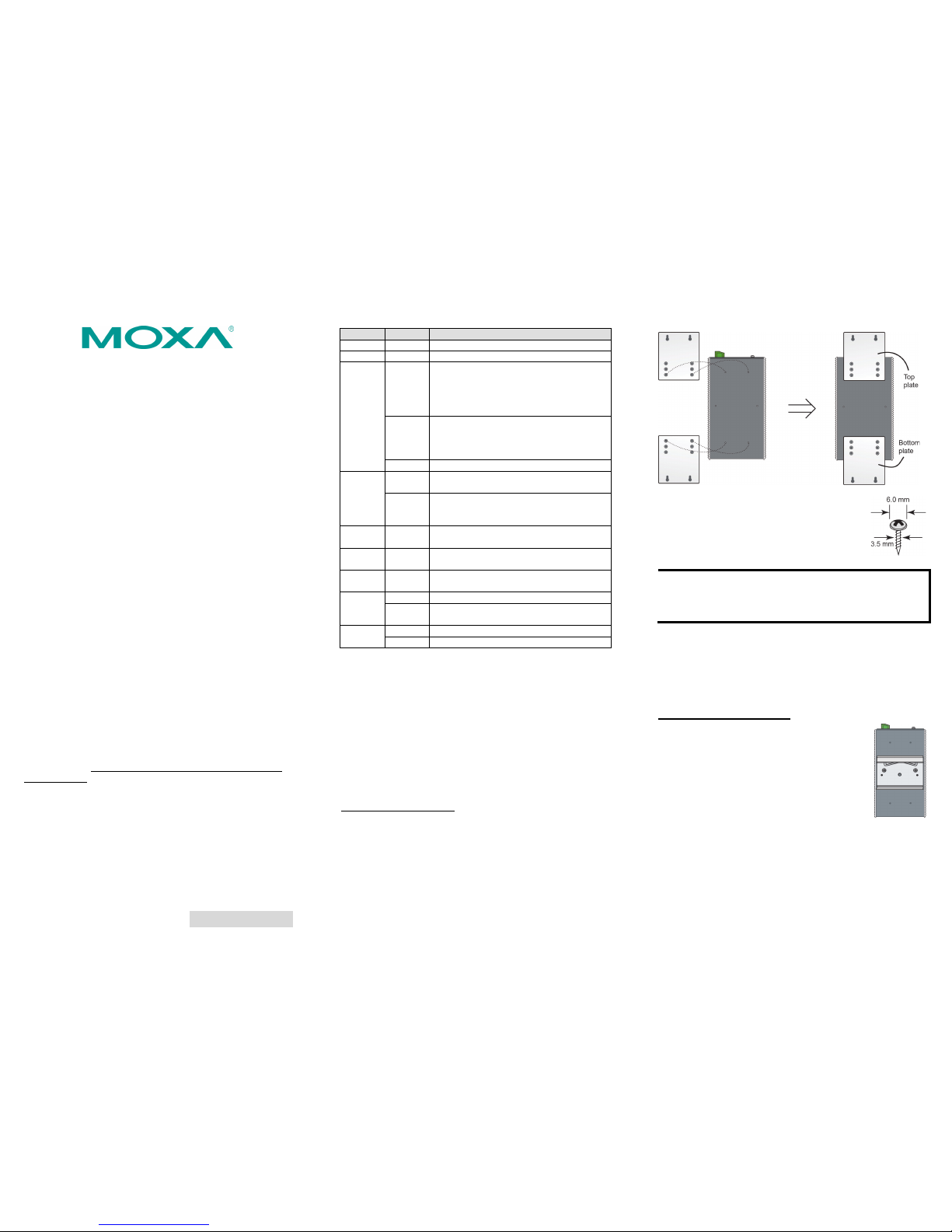
Wall Mounting (optional)
In high vibration environments, we suggest using the NP ort
S8000’s wall moun t kit to fix. The installation pr ocedure iss
described be low.
STEP 1: Remove the aluminum DIN-Rail attachment plate from
the NPort S8000’s rear panel, and then atta ch the wall moun t
plates with M3 screws.
STEP 2: Four screws are required. Use the NPort
S8
000, with wall mount plates attached, as a
guide to
mark the correct locations of the 4
screws. The heads of the
screws should be less
than 6.0 mm in diameter, and the shafts should be
less than 3.5 mm in diameter.
NOTE Before tightening the screws into the wall, make sure the
screw head and shank size are suitable by inserting one of
the screw
s into one of the keyhole-
shaped apertures of the
wall mounting plates.
Do not screw the screws in completely—leave about 2 mm to allow
room for sliding the wal l mount panel bet ween the wall and t he
screws.
STEP 3: Once the screws are fixed to the wall, inser t the four
screw heads through the large parts of the keyhole-s haped
apertures, and then slide the NPort S8000 downwards, as
indicated. Tighten the four screws for added stability.
DIN-Rail Mounting (optional)
DIN
-Rail attachments can
be purchased separately
to attach the product to
a DIN-R
ail. When snapp ing
the attachments to the DIN
-Rail, make sur e
that the
stiff metal springs are at the top.
Page 2
– 4 – – 5 – – 6 –
www.moxa.com/support
The Americas:
+1-714-528-6777 (toll-free: 1-888-669-2872)
Europe:
+49-89-3 70 03 99-0
Asia-Pacific:
+886-2-8919-1230
China:
+86-21-5258-9955 (toll-free: 800-820-5036)
2014 Moxa Inc. All r ights reserved.
Turbo Ring DIP Switch Settings
The default setting for each DIP switch is OFF. The
following table explains the effe ct of setting the DIP
switch to the ON position.
Turbo Ring Setting s
DIP
DIP 1
DIP 2
DIP 3
DIP 4
– Ring Master Ring Couplin g
port
DIP 1, 2, 3
ON – Enable
Enable
Activates
Default
OFF – Disable
Disable
Disabled
Turbo Ring V2 Settings
DIP
DIP 1
DIP 2
DIP 3
DIP 4
Ring
Coupling
Ring
Master
Ring
Coupling port
DIP 1, 2, 3
ON Backup port
Enable
Enable Enable Activates
Default
OFF
Primary port
Enable
Disable
Disable
Disabled.
Software Installation Information
The documentation and s oftware CD contain s the user’s manual,
driver, SNMP MIB, and NPort Search Utility. Insert the CD you’re
your computer and follow the on-screen instructions. Please refer
to the user’s manual for additional details on using the NPort
Search Utility, driver, and SNMP MIB.
Pin Assignments and Cable Wiring
DB9 Male Port Pinouts
Pin
RS-232
RS-422/
RS-485-4w
RS-485-2w
1
DCD
TxD-(A)
– 2 RxD
TxD+(B)
– 3 TxD
RxD+(B)
Data+(B)
4
DTR
RxD-(A)
Data-(A)
5
GND
GND
GND 6 DSR – – 7 RTS – – 8 CTS – – 9 – – –
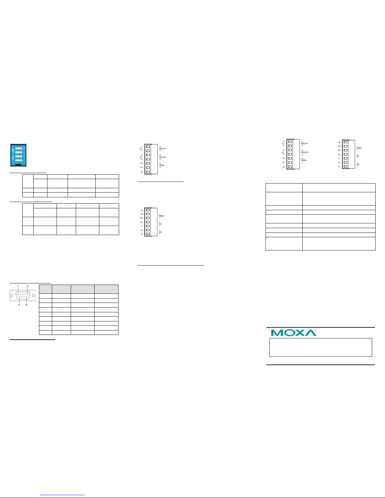
Wiring the Relay Contact
The NPort S8000 has two sets of relay outputs—relay 1 and relay
2. Each relay contact consists of two contacts of the terminal block
on the NPort S8000’s top panel. Refer to the next section for
detailed instructions on how to connect the wires to the terminal
block connector, and how to attach the terminal block connector to
the terminal block receptor. The meaning of the two contacts used
to connect the relay contacts is illustrated below.
The fault ci
rcuit will ope n if
1.
A relay warning event is triggered, OR
2.
The NPort S8000 is t he
Master of this Turbo
Ring, and the Turbo Ring is disconnected,
OR
3.
Start-up fails.
If none of these three conditions is met, the fault
circuit will remain closed.
Wiring the Digital Inputs
The NPort S8000 unit has two sets of digital inputs: DI 1 and DI 2.
Each DI consists of two contacts of the 6-pin termina l block
connector on the NP ort S8000’s top panel. The remaining contacts
are used for the NPort S800 0’s two DC inputs. Top and front views
of one of the terminal block connectors are shown below.
Take the follow ing steps to wire the digital
inputs:
1. Insert the negative (ground) or positive DI
wires into the te rminals.
2.
To keep the DI wires from getting loose,
use a small flat -blade screwdriver to
tighten the wire-
clamp screws on the front
of the terminal block connector.
3. Insert the plastic terminal block connector
prongs into the terminal block receptor,
which is located on the NPort 8000’s top
panel.
Wiring the Redundan t Power Inp uts
The NPort S8000 unit has two sets of power inputs—power input 1
and power input 2. The top two contacts and the bottom two
contacts of the 6-pin terminal block connector on the top panel are
used for the NPort S8000’s two power inputs. Top and front views
of one of the terminal block connectors are shown below.
Take the following steps to wire the redundant power inputs:
1. Insert the negative/positive DC wires into the V-/V+ terminals.
2. To keep the DC wires from pulling loose, use a small flat-b lade
screwdriver to tighten the wire-clamp screws on the front of
the terminal block connector.
3. Insert the plastic terminal block connector prongs into the
terminal block receptor, which is located on the NPort S8000’s
top panel.
Terminal 1
Terminal 2
Specifications
Power
Requirements
12 to 48 VDC, 940 mA at 12V (ma x.)
Operating Temp.
Standard Model: 0 to 60°C (32 to 140°F)
Wide Temp. Model: -40 to 85°C
(-40 to 185°F)
Operating Humidity
5 to 95% RH
Dimensions
93 × 125 × 144 mm (3.66 × 4.92 × 5.64 in)
EMC
CE (EN 55022 Class A, EN 55024),
FCC Part 15 Subpart B Class A
Safety
UL (UL 60950-1), LVD (EN 60950-1)
ESD
IEC 61000-4-2, Level 4
EFT
IEC 61000-4-4, Level 4
Surge Protection
Serial Port: IEC 61000-4-5 Level 4
Ethernet Port: IEC 61 000-4-5 Level 4
Power Li ne: IEC 61000 -4-5 Level 4
 Loading...