

Page 1

P/N: 1802051500214
*1802051500214*
NPort IA5150/5250 Series
Quick Installation Guide
Edition 6.0, April 2016
Technical Support Contact Information
www.moxa.com/support
Moxa Americas:
Toll
-free: 1-888-669-2872
Tel:
1-714-528-6777
Fax:
1-714-528-6778
Moxa China (Shanghai office):
Toll
-free: 800-820-5036
Tel:
+86-21-5258-9955
Fax:
+86-21-5258-5505
Moxa Europe:
Tel:
+49-89-3 70 03 99-0
Fax:
+49-89-3 70 03 99-99
Moxa Asia-Pacific:
Tel:
+886-2-8919-1230
Fax:
+886-2-8919-1231
Moxa India:
Tel:
+91-80-4172-9088
Fax:
+91-80-4132-1045
2016 Moxa Inc. All rights reserved.
Page 2
- 2 -
Overview
NPort IA device servers deliver easy and reliable serial-to-Ethernet
connectivity for the industrial automation market. The servers support
several operation modes—TCP Server, TCP Client, UDP, Real COM, Pair
Connection, and Ethernet Modem—ensuring the compatibility of network
software, and they are an ideal choice for connecting RS-232/422/485
serial devices, such as PLCs, sensors, meters, motors, drives, barcode
readers, and operator displays. NPort IA device servers come with a
compact and rugged DIN-rail mountable casing.
Package Checklist
Before installing NPort IA device servers, verify that the package contains
the following items:
• 1 NPort IA series device server
• Documentation and software CD
• NPort IA series quick installation guide
Optional Accessories
• DR-4524: 5W/2A DIN-rail 24 VDC power supply with universal 85 to
264 VAC input
• DR-75-24: 75W/3.2A DIN-rail 24 VDC power supply with universal
85 to 264 VAC input
• DR-120-24: 120W/5A DIN-rail 24 VDC power supply with 88 to 132
VAC/176 to 264 VAC input by switch
Note: Notify your sales representative if any of the above items are
missing or damaged.
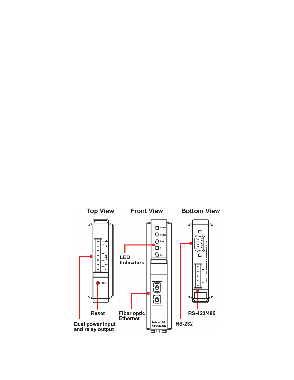
NPort IA5150 Series Appearance
Page 3

- 3 -
NPort IA5250 Appearance
Reset Button—Press the Reset button for 5 seconds to load factory
defaults. Use a pointed object, such as a straightened paper clip or
toothpick, to press the reset button. This will cause the Ready LED to blink
on and off. The factory defaults will be loaded once the Ready LED stops
blinking (after about 5 seconds). At this point, you should release the
reset button.
NPort IA LED Indicators (front panel)
Name
Color
Function
PWR1,PWR2 Red
Power is being supplied to power input PWR1,
PWR2.
Ready
Red
Steady on: Power is on, and the NPort IA is
booting up.
Blinking: Indicates an IP conflict, the DHCP or
BOOTP server did not respond properly
, or a relay
output occurred.
Green
Steady on: Power is on, and the NPort IA is
functioning normally.
Blinking: The device server has been located by
the Administrator’s Location function.
Off
Power is off, or a power-error condition exists.
Ethernet
Orange
10 Mbps Ethernet connection.
Green
100 Mbps Ethernet connection.
Off
Ethernet cable is disconnected, or has a short.
P1, P2
Orange
Serial port is receiving data.
Green
Serial port is transmitting data.
Off
No data is being transmitted or received through
the serial port.
FX Orange
Steady on: Ethernet fiber connection, but port is
idle.
Blinking: Fiber port is transmitting or receiving
data.
Page 4

- 4 -
Hardware Installation Procedure
STEP 1: After removing the NPort IA from the box, the first thing you
should do is connect the power adapter. Connect the 12-48 VDC power
line with the NPort IA’s terminal block, or connect the DIN-rail power
supply with the NPort IA’s terminal block.
STEP 2: Connect the NPort IA to a network. Use a standard
straight-through Ethernet cable to connect to a hub or switch. When
setting up or testing the NPort IA, you might find it convenient to connect
directly to your computer’s Ethernet port. In this case, use a crossover
Ethernet cable.
STEP 3: Connect the NPort IA’s serial port to a serial device.
STEP 4: The NPort IA is designed to be attached to a DIN rail or mounted
on a wall. The two sliders on the NPort IA’s rear panel serve a dual
purpose. For wall mounting, both sliders should be extended. For DIN-rail
mounting, start with one slider pushed in, and the other slider extended.
After attaching the NPort IA on the DIN rail, push the extended slider in to
lock the device server to the rail. The two placement options are
illustrated in the accompanying figures.
Wallmount DIN Rail
Software Installation Information
To install NPort Administration Suite, insert the Document &
Software CD into your computer’s CD-ROM drive. Once the installation
window opens, click on the Install Administration Suite button and
follow the instructions on the screen. To view detailed information about
NPort IA Administration Suite, click on the Documents button and select
NPort IA5150/5250 Series User’s Manual to open the PDF version of
this user’s manual.
Page 5

- 5 -
Pin Assignments and Cable Wiring
RS-232/422/485 (Male DB9) Pinouts
PIN
RS-232
RS-422/RS-485 (4W)
RS-485 (2W)
1
DCD
TxD-(A)
–
2
RXD
TxD+(B)
–
3
TXD
RxD+(B)
Data+(B)
4
DTR
RxD-(A)
Data-(A)
5
GND
GND
GND
6
DSR – –
7
RTS – –
8
CTS – –
9
– – –
4W/2W RS-485/RS-422 (Terminal Block) Pinouts
PIN RS-485 (2W)
RS-422/
RS-485 (4W)
1 – TxD+(B)
2 – TxD-(A)
3
Data+(B)
RxD+(B)
4
Data-(A)
RxD-(A)
5 – GND
Four cables are available as optional accessories that can be used to
connect the NPort IA to RS-232 serial devices. For your convenience, we
show precise cable wiring diagrams for each of the two cables.
Female DB9 to Male DB9
Page 6

- 6 -
Female DB9 to Male DB25
ATEX and IECEx Information
1. Certificate number: DEMKO 07 ATEX 0690059x
2. Ambient range (-40°C ≤ Tamb ≤ 75°C)
3. Certification string (Ex nA IIC T3)
4. Standards covered (EN60079-0:2006, EN60079-15:2005, IECEx UL
13.0023X, IEC 60079-0 Ed. 6, IEC 60079-15 Ed. 4)
5. Conditions of safe usage:
The Ethernet Communication Devices are to be mounted in an IP54
enclosure and used in an area with a pollution degree of not more
than 2, as defined by IEC 60664-1.
A 4-mm
2
conductor must be used when a connection to the external
grounding screw is utilized.
Conductors suitable for use in an ambient temperature of 114°C must
be used for the Power Supply Terminal.
Provisions shall be made, either in the apparatus or external to the
apparatus, to prevent the rated voltage to exceed the transient
disturbance by more than 40%.
 Loading...