

Page 1

P/N: 1802051504012
*1802051504012*
NPort IA5000A-I/O Series
NPort IAW5000A-I/O Series
Quick Installation Guide
Edition 2.0, November 2017
Technical Support Contact Information
www.moxa.com/support
Moxa Americas:
Toll
-free: 1-888-669-2872
Tel:
1-714-528-6777
Fax:
1-714-528-6778
Moxa China (Shanghai office):
Toll
-free: 800-820-5036
Tel:
+86-21-5258-9955
Fax:
+86-21-5258-5505
Moxa Europe:
Tel:
+49-89-3 70 03 99-0
Fax:
+49-89-3 70 03 99-99
Moxa Asia-Pacific:
Tel:
+886-2-8919-1230
Fax:
+886-2-8919-1231
Moxa India:
Tel:
+91-80-4172-9088
Fax:
+91-80-4132-1045
2017 Moxa Inc. All rights reserved.
Page 2

- 2 -
Overview
The NPort IA5000A-I/O and IAW5000A-I/O Series consist of serial device
servers with Digital Input/Output (DIO), providing maximum flexibility to
integrate serial equipment in the field into Ethernet networks for a variety
of industrial data acquisition applications. The DIO on a device can be
controlled over TCP/IP, using the Modbus TCP protocol, and it can be
configured and secured from a web browser.
Package Checklist
Before installing the NPort IA5000A-I/O or NPort IAW5000A-I/O Series
device server, verify that the package contains the following items:
• NPort IA5000A-I/O or NPort IAW5000A-I/O device server with digital
I/O
• Antenna (for the NPort IAW5000A-I/O Series)
• Quick installation guide (printed)
• Warranty card
Optional Accessories
• Mini DB9F-to-TB Adapter: DB9-female-to-terminal-block adapter
for RS-422/485 applications
• WK-51-01: Wall-mounting kit
• DR-4524: 45W/2A DIN-rail 24 VDC power supply with universal 85
to 264 VAC input
• DR-75-24: 75W/3.2A DIN-rail 24 VDC power supply with universal
85 to 264 VAC input
• DR-120-24: 120W/5A DIN-rail 24 VDC power supply with 88 to 132
VAC or 176 to 264 VAC input, selected by a DIP switch
Notify your sales representative if any of the above items are missing or
damaged.
Hardware Introduction
As shown in the following figures, the NPort IA5000A-I/O Series has two
Ethernet RJ45 LAN ports, and the NPort IAW5000A-I/O Series has one
Ethernet RJ45 LAN port and one antenna for WiFi (IEEE 802.11 standards)
signal communication, supporting 2.4GHz and 5 GHz frequencies. Both
series are equipped with four DIs and two DOs for data acquisition
applications. The NPort IA5000A-I/O and IAW5000A-I/O device server
series come with built-in 4 kV serial port surge protection.
Page 3
- 3 -
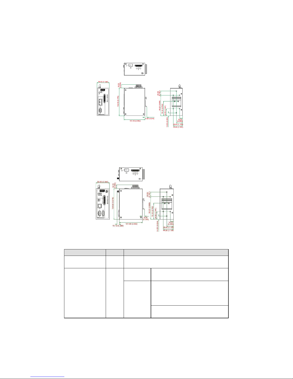
NPort IA5000A-I/O Series
The mechanical design of the NPort IA5000A-I/O Series is mostly
identical; only the number of serial ports and number of DI/DO channels
differ.
NPort IAW5000A-I/O Series
The mechanical design of the NPort IAW5150A and the NPort IAW5250A
is mostly identical; only the number of serial ports and number of DI/DO
channels differ.
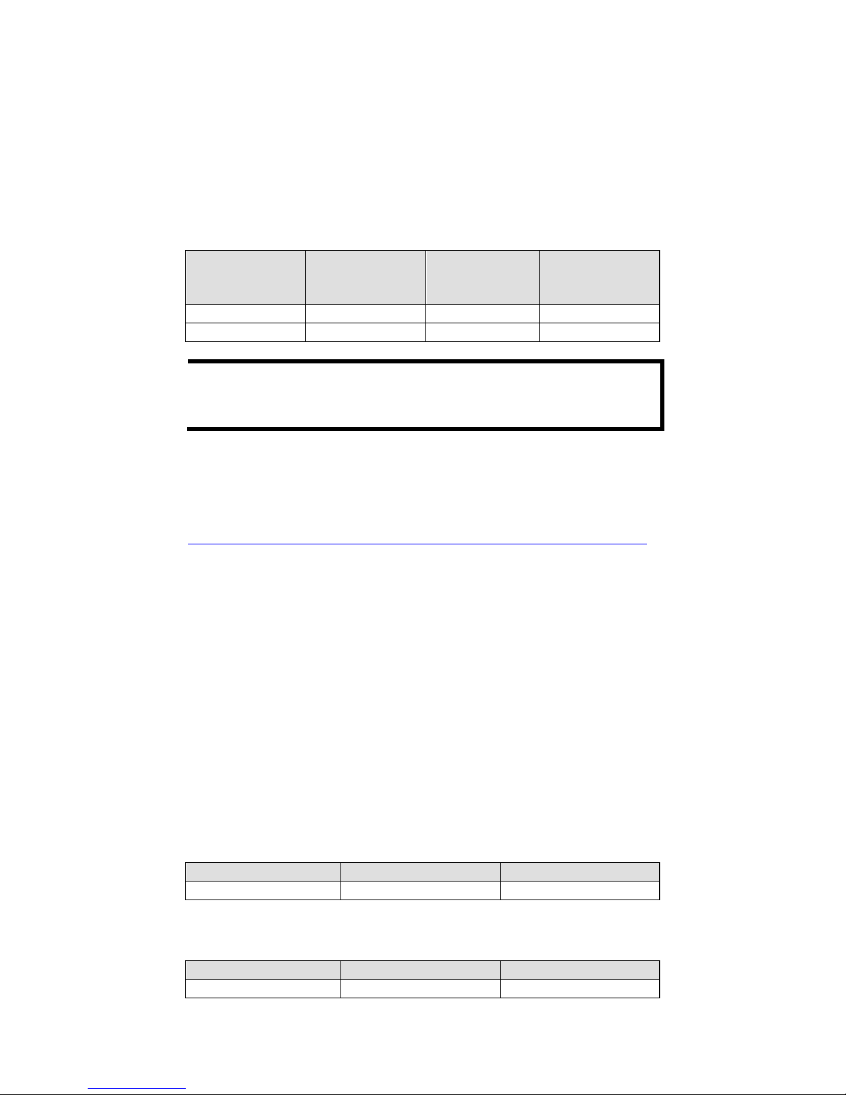
LED Indicators
Name
Color
Function
PWR 1,
PWR 2
Green
Power is being supplied to power input PWR1,
PWR2.
Ready
Red
Steady on
Power is on, and the NPort is
booting up.
Blinking
Indicates an IP conflict, or the
DHCP or BOOTP server did not
respond properly, or a relay
output occurred.
When the above two conditions
occur at the same time.
Page 4

- 4 -
Check the relay output first. If the
Ready LED is still blinking after
resolving the relay output, then
there is an IP conflict, or the DHCP
or BOOTP server did not respond
properly.
Flashing
quickly
microSD card failed
Green
Steady on
Power is on, and the NPort is
functioning normally.
Blinking The device server has been
located by Administrator’s
Location function
Off
Power is off, or a power error condition exists.
WLAN (Only for
the NPort
IAW5000A-I/O)
Green
Steady on
Wireless is enabled
Blinking
NPort can’t establish WLAN
connection with AP
(Infrastructure) or station
(Ad-Hoc)
Off
Wireless is not enabled.
Signal Strength
(3 LEDs only for
the NPort
IAW5000A-I/O)
Green
1 Bottom
The signal strength (RSSI) is less
than -74 dBm
2 Middle
The signal strength (RSSI) is
between -65 to -74 dBm
3 Top
The signal strength (RSSI) is
greater than -65 dBm
Ethernet
Amber
10 Mbps Ethernet connection
Green
100 Mbps Ethernet connection
Off
The Ethernet cable is disconnected or has a
short.
P1, P2 (Serial)
Amber
Serial port is receiving data.
Green
Serial port is transmitting data
Off
No data is being transmitted or received
through the serial port.
DI
Green
DI status on
Off
DI status off
DO
Green
DO status on
Off
DO status off
Hardware Installation Procedure
STEP 1:
After unpacking the unit, connect the power supply to the unit.
STEP 2:
Use an Ethernet cable to connect the unit to the network.
STEP 3:
Connect your device to the desired port on the unit.
STEP 4:
Place or mount the unit. The unit may be placed on a
horizontal surface such as a desktop, or mounted on the wall.
Mounting Options
The NPort IA5000A-I/O and IAW5000A-I/O are designed to be attached
to a DIN rail or mounted on a wall.
Page 5

- 5 -
STEP 1:
Insert
the top of the
DIN rail into the
slot.
STEP 2:
The
DIN rail
attachment unit
will snap into
place as shown
at right.
Wall Mounting (optional)
For some applications, it may be more convenient to mount the NPort
IA5000A-I/O or IAW5000A-I/O to a wall, as illustrated below.
Do not drive the screws in all the way—leave a space of about 2 mm to
allow room for sliding the wall-mounting panel between the wall and the
screws.
NOTE
Test the screw head and shank size by inserting the screws into
one of the keyhole
-shaped apertures of the wall-
mounting plates
before they are fixed to the wall.
STEP 3:
Once the screws are fixed into the wall, insert the four screw heads
through the large opening of the keyhole-shaped apertures, and then
slide the NPort downwards, as indicated to the right. Tighten the screws
for added stability.
Termination Resistor and Adjustable Pull-Up/Down Resistors
In some critical environments, you may need to add termination resistors
to prevent the reflection of serial signals. When using termination
resistors, it is important to set the pull-up/down resistors correctly so that
the electrical signal is not corrupted. The NPort IA5000A-I/O and
IAW5000A-I/O Series use DIP switches to set the pull-up/down resistor
values for each serial port. The DIP switches are located at the side of
wireless device server for easy setting.
Page 6
- 6 -
To add a 120 Ω termination resistor, set switch 3 on the port’s
assigned DIP switch to ON; set switch 3 to OFF (the default setting) to
disable the termination resistor.
To set the pull-up/down resistors to 150 KΩ, set switches 1 and 2 on
the port’s assigned DIP switch to OFF. This is the default setting.
To set the pull-up/down resistors to 1 KΩ, set switches 1 and 2 on
the port’s assigned DIP switch to ON.
Pull-Up/Down Resistors for the RS-485 Port
SW1 (Serial 1)
SW2 (Serial 2)
DIP 1
Pull-up resistor
DIP 2
Pull-down
resistor
DIP 3
Terminal resistor
ON
1 KΩ
1 KΩ
120 Ω
OFF (Default)
150 KΩ
150 KΩ
N/A
NOTE
Do not use the 1 KΩ setting while in RS-232 mode. Doing so will
degrade the RS
-232 signals and reduce the effective
communication distance.
Software Installation Information
For software installation, download the relative utilities from Moxa’s
website:
https://www.moxa.com/support/support_home.aspx?isSearchShow=1
• Download the NPort Windows Driver Manager and install it as
the driver to run with Real COM mode of the NPort Series.
• Execute NPort Windows Driver Manager; then map the virtual
COM ports on your Windows platform.
• You may refer to the DB9 Male pin assignment section to loop
back pin 2 and pin 3 for the RS-232 interface to carry out a
self-test on the device.
• Use HyperTerminal or a similar program (you may download
Moxa’s program, called PComm Lite) to test whether the device
is good or not.
Setting the IP Address
The factory default IP settings are assigned as follows:
NPort IA5000A-I/O Series
LAN
IP
Netmask
Static
192.168.127.254
255.255.255.0
NPort IAW5000A-I/O Series
LAN
IP
Netmask
Static
192.168.126.254
255.255.255.0
Page 7

- 7 -
WLAN
IP
Netmask
Static
192.168.127.254
255.255.255.0
If the NPort is configured for DHCP but the DHCP server cannot be found,
the NPort will use factory default IP settings.
NOTE
If you have forgotten the NPort’s IP address, use the Device
Search Utility from your PC to locate the NPort. After searching
the LAN for NPort units, the
Device
Search Utility will display the
IP address of each unit.
NOTE
(
For the NPort IAW5000A-I/O Series)
Ethernet Bridge Disabled (default):
Only one network
interface can be active at a time. If the Ethernet link is active, the
WLAN will be inactive. If the WLAN is active, the Ethernet link will
be inactive.
Ethernet Bridge Enabled:
The LAN and WAN will both be
active. Go to the web console,
find the network settings page,
and set Ethernet Bridge to Enabled.
Open the web console to make the configuration changes as follows:
STEP 1: Open your web browser.
STEP 2: In the address bar, enter the default IP address (for the NPort
IA5000A-I/O Series, it is 192.168.127.254; for the NPort IAW5000A-I/O
Series, it is 192.168.126.254)
STEP 3: The web server will ask for the username and password before
you log in. To configure the device server, you may use the default
user/default password admin/moxa to log in the web console.
STEP 4: For first-time use, click the Wizard in the left navigation panel.
The wizard will prompt you to configure the IP address and basic settings.
For other settings, use the factory defaults or modify the settings for your
application.
Pin Assignments
RJ45 (LAN)
Pin
LAN
1
Tx+
2
Tx-
3
Rx+ 4 – 5 – 6 Rx- 7 – 8 –
Page 8

- 8 -
DB9 Male (RS-232/422/485)
Pin RS-232
RS-422/
RS-485-4W
RS-485-2W
1
DCD
TxD-(A)
–
2
RxD
TxD+(B)
–
3
TxD
RxD+(B)
Data+(B)
4
DTR
RxD-(A)
Data-(A)
5
GND
GND
GND
6
DSR – –
7
RTS – –
8
CTS – – 9 – – –
Power Input and Relay Output Pinouts
V2+ V2-
V1+ V1-
DC Power
Input 2
DC Power
Input 2
N.O. Common N.C.
DC Power
Input 1
DC Power
Input 1
DI/DO Pinouts
DO0
DO1
GND
DI0
DI1
DI2
DI3
COM
GND
Digital
Output
0
Digital
Output
1
Ground
Digital
Input
0
Digital
Input
1
Digital
Input
2
Digital
Input 3 Common Ground
Specifications
Power Input
12 to 48 VDC
Power Consumption
NPort IA5000A-I/O: 300mA @12V
NPort IAW5000A-I/O: 300mA @12V
Operating Temperature Standard models:
0 to 60°C (32 to 140°F)
Storage Temperature
-40 to 85°C (-40 to 185°F)
Operating Humidity
5 to 95% RH
Dimensions (W x D x H)
NPort IA5000A-I/O:
59.6 x 101.4 x 134 mm (2.35 x 4.0 x 5.28 in)
IAW5000A-I/O:
59.6 x 101.4 x 134 mm (2.35 x 4.0 x 5.28 in)
Magnetic Isolation
1.5 kV for Ethernet
Regulatory Approvals
EMC
CE: EN 61000-6-2/6-4
FCC: FCC Part 17 Subpart B, Class A
Page 9
- 9 -
FCC Part 15 Subpart B, Class A
Safety
UL: UL 60950-1
LVD: EN 60950-1
DSPR: ARIB-STD 33, ARIB-STD 66
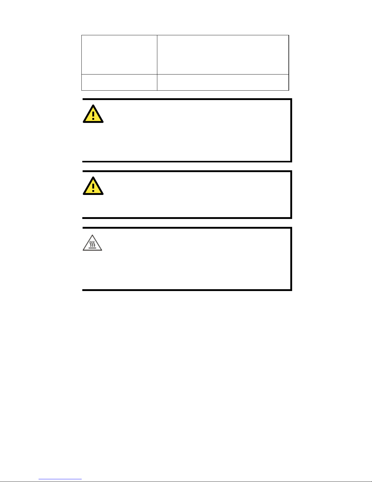
Fault Relay Circuit
3-pin circuit with current-carrying capacity of
2 A @ 30 VDC
ATTENTION
This product is intended to be supplied by an UL
listed DC
source
suitable for use at T
MA of 60 degree C, which
output meets SELV
circuit and LPS
, which is separated from the primary circuit by
double insulation or reinforced insulation, and is rated 12-48Vdc,
0.38-0.1A or min. 0.38A; or 24Vdc, min. 0.17A.
ATTENTION
The risk of an
explosion is very high if the
battery is replaced by
an incorrect type. Dispose of used batteries according to the
instructions.
ATTENTION
This equipment is intended to be used in Restricted Access
Location.
WARNING:
HOT SURFACE. DO NOT TOUCH! Before touching the surface, pay
special attention and take the necessary protection measures.
 Loading...