

Page 1

NPort Express DE-211
Hardware Installation Guide
For DE-211
Edition 9.1, September 2017
www.moxa.com/product
© 2017 Moxa Inc. All rights reserved.
Page 2

NPort Express DE-211
Hardware Installation Guide
The software described in this manual is furnished under a license
agreement and may be used only in accordance with the terms of that
© 2017 Moxa Inc. All rights reserved.
The MOXA logo is a registered trademark of Moxa Inc.
All other trademarks or registered marks in this manual belong to their
Information in this document is subject to change without notice and does
not represent a commitment on the part of Moxa.
Moxa provides this document as is, without warranty of any kind, either
expressed or implied, including, but not limited to, its particular purpose.
Moxa reserves the right to make improvements and/or changes to this
manual, or to the products and/or the programs described in this manual,
at any time.
Information provided in this manual is intended to be accurate and
reliable. However, Moxa assumes no responsibility for its use, or for any
infringements on the rights of third parties that may result from its use.
This product might include unintentional technical or typographical errors.
Changes are periodically made to the information herein to correct such
errors, and these changes are incorporated into new editions of the
publication.
agreement.
Copyright Notice
Trademarks
respective manufacturers.
Disclaimer
Page 3

Moxa Americas
Toll
Tel:
Fax:
Moxa China (Shanghai
office)
Toll
Tel:
Fax: +86-21-5258-5505
Moxa Europe
Tel:
Fax: +49-89-3 70 03 99-99
Moxa Asia-Pacific
Tel:
Fax: +886-2-8919-1231
Technical Support Contact Information
www.moxa.com/support
-free: 1-888-669-2872
+1-714-528-6777
+1-714-528-6778
+49-89-3 70 03 99-0
-free: 800-820-5036
+86-21-5258-9955
+886-2-8919-1230
Page 4

Table of Contents
1. Introduction ............................................................. 6
Features .................................................................... 7
Product Specifications .................................................. 8
Package Checklist ........................................................ 9
Front/Top/Rear/Bottom Panel Views ............................. 10
2. Overview ................................................................ 11
LED Indicators ........................................................... 12
Housing .................................................................... 13
DIN Rail .................................................................. 13
Wall Mount.............................................................. 14
3. Serial Installation .................................................. 15
DIP Switch Settings .................................................... 16
Female DB25 Connector Pinout .................................... 17
RS-232 Wiring ........................................................... 17
RS-422 Wiring ........................................................... 19
Using a DB25 Connector ........................................... 19
Using the Optional Terminal Block .............................. 20
RS-485 Wiring ........................................................... 20
Using a DB25 Connector ........................................... 20
Using the Optional Terminal Block .............................. 21
Enabling a Termination Resistor ................................... 23
Enabling the Built-In 120 Ω Terminator ...................... 23
Enabling a User-Supplied Terminator ......................... 24
4. Ethernet Installation .............................................. 25
Connecting to the Ethernet Port ................................... 26
Connecting to a Hub or Switch .................................. 26
Connecting to a PC .................................................. 26
5. Power Connection .................................................. 27
Using the Power Adapter ............................................. 28
Using Power Over Serial .............................................. 28
Power Status Check .................................................... 31
A. Return Procedure ................................................... 32
Page 5

B. Compliance Notice .................................................. 33
Page 6

Features
Front/Top/Rear/Bottom Panel Views
1
1. Introduction
Welcome to Moxa NPort Express, a compact palm-sized communications
device that allows you to control RS-232/422/485 serial devices over a
TCP/IP Ethernet.
The following topics are covered in this chapter:
Product Specifications
Package Checklist
Page 7

NPort Express DE-211 Introduction
7
NPort Express DE-211 provides a data communications solution for
connecting Windows and Linux hosts to asynchronous serial devices over
a TCP/IP Ethernet. You may connect your Windows host to a native
RS-232/422/485 serial port, or your PC-based Linux host to a real tty port,
through a TCP/IP Ethernet. With one asynchronous serial port connection
on one end, and a 10 Mbps Ethernet connection on the other, NPort
Express allows virtually any serial device to attach to a network. NPort
Express works like an add-on single-port serial board to your PC server,
but with one major advantage—the TCP/IP network. Since the host
communicates with the COM port on NPort Express over a TCP/IP network,
you are able to control your asynchronous serial device from virtually any
location.
Although it connects through the virtual link of the Ethernet, the port on
NPort Express is recognized as a real COM port by Windows or a real tty
port by Linux. NPort Express provides both the basic transmit/receive
data functions, as well as RTS, CTS, DTR, DSR, and DCD control signals.
NPort Express can be used with your existing applications that support
serial communication, and come with a utility program providing a simple
step-by-step installation procedure and a maintenance wizard that gives
you easy access to your asynchronous device.
Features
• 3-in-1 RS-232/422/485 interface and 10 Mbps Ethernet
• Supports 4- and 2-wire RS-485 with patented ADDC™ and built-in
terminator
• Supports industrial 12/24 VDC power input and optional Power over
Serial
• Terminal block accessory for easy RS-422/485 serial wiring
• Supports MAC based IP configuration
• Supports configuration store and copy for easy deployment
• Supports Windows Real COM driver and Linux real TTY driver
• Supports Driver Mode, TCP Server/Client, UDP Server/Client,
Ethernet Modem, Pair Connection
Page 8

NPort Express DE-211 Introduction
8
Interface
LAN: 10BaseT
Serial: RS-232/422/485 (DIP switch selectable)
Number of Ports: 1
RS-485 4-wire: TxD+/-, RxD+/-, GND
Performance
Speed: 150 bps to 230.4 Kbps
Configuration
Parity: None, Even, Odd, Space, Mark
Data Bits: 5, 6, 7, 8
Stop Bits: 1, 1.5, 2
OS Supported
FreeBSD 5, FreeBSD 6
Operation Modes
Modem, Pair Connection
Management
Firmware upgrade function supported
Power and Environment
Power requirements: DC 12V to 30V
92 mA (max.) at 24
Operating temp.: 0 – 55◦C
Operating humidity: 5 – 95% RH
Dimensions (W×D×H): 90 × 100.4 × 22 mm (with ears),
Product Specifications
Signals:
RS-232: TxD, RxD, RTS, CTS,DTR, DSR, DCD, GND
RS-422: TxD+/-, RxD+/-, GND
RS-485 2-wire: Data+/-, GND
Real COM drivers for: Windows
95/98/ME/NT/2000/XP/2003/Vista/2008/7/XP x64/2003 x64/Vista
x64/2008 x64/7 x64
Real TTY driver for: Linux 2.4.x, 2.6.x kernel
Fixed TTY drivers for: SCO Unix, SCO OpenServer 5,OpenServer 6,
UnixWare 7, UnixWare 2.1, SVR4.2, QNX 4.25, QNX 6, Solaris 10,
Driver Mode, TCP Server, TCP Client, UDP Server/Client, Ethernet
Serial conso le
Telnet console
NPort Configurator for Windows/Linux
Real COM Installer for Windows
Monitor Utility for Windows
150 mA (max.) at 12V
Page 9

NPort Express DE-211 Introduction
9
67 × 100.4 × 22 mm (without ears)
Surge protection: 15 KV ESD (RS-232), 12KV ESD (RS-422/485)
Magnetic isolation: 1.5 KV for Ethernet
Regulatory approvals: EMC: CE Class B, FCC Class B
Safety: UL 60950-1, EN 60950-1
Package Checklist
• 1 NPort Express DE-211
• Quick Installation Guide
• NPort Documentation & Software CD
• Product Warranty Booklet
Optional Accessories
NP21101 30 cm DB25 male to DB9 female RS-232 cable
NP21102 30 cm DB25 male to DB9 male RS-232 cable
NP21103 DB25 termina l block kit for RS-422/485
DK-35A For 35 mm DIN Rail; includes 4 screws
Page 10
NPort Express DE-211 Introduction
10
1.
ready LED will flash
ase the
button at this
ready LED will flash
on/off every fifth of
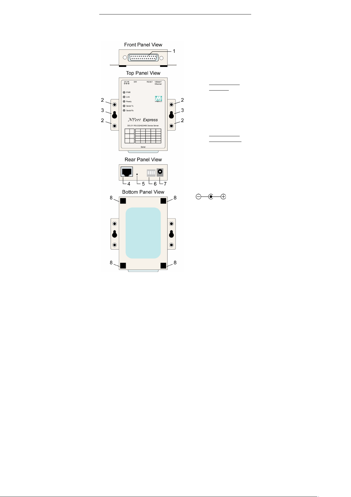
Front/Top/Rear/Bottom Panel Views
Female DB25 serial port
2. DIN Rail screw holes
3. Wall mount screw holes
4. RJ45 10BaseT Ethernet
port
5. Reset button—press
continuously for
a. 3 sec to erase
password
After3 sec, the
on/off every half
second. Rele
reset
time to erase
password.
b. 10 sec to load
factory defaults
After 10 sec, the
a second. Release
the reset button at
this time to load
factory defaults.
6. DIP Switches
7. Power input
8. Rubber base pads
Page 11

LED Indicators
Wall Mount
The following topics are covered in this chapter:
Housing
DIN Rail
2
2. Overview
Page 12

NPort Express DE-211 Overview
12
LED Name
LED Color
LED Function
red
Power is on.
off
Power is off, or power error condition exists.
Link
orange
10 Mbps Ethernet connection.
off
Ethernet cable is disconnected, or has a
short.
Ready
green
NPort Server system is ready.
blinking
NPort is requesting an IP address from the
the reset button; see page 1-5 for details.
off
NPort Server has malfunctioned.
green
Serial data is being transmitted.
off
Serial data is not being transmitted.
Serial Rx
orange
Serial data is being received.
off
Serial data is not being received.
LED Indicators
NPort Express’s top panel contains five LED indicators, as described in the
following table.
PWR
DHCP or BootP server. After receiving the
IP, the LED will stop blinking.
Note: The LED will also blink when you press
Serial Tx
Page 13

NPort Express DE-211 Overview
13
STEP 1: Use 2 screws per ear to attach DIN Rail mounts to each of NPort
Express’s two ears.
⇒
STEP 3: Push the bottom of NPort
Express so that the bottom of the
DIN Rail mount.
NOTE
The Din Rail mounting kit is an optional accessory.
Housing
DIN Rail
For many industrial applications, you will find it convenient to use the DIN
Rail attachments, as shown below.
STEP 2: Insert the top of the DIN Rail
into slot A of the DIN Rail mount.
DIN Rail snaps into slot B of the
To remove NPort Express from the DIN Rail, simply reverse Steps 2 and 3
above by grasping the bottom of the NPort Express unit with both hands,
and then using your fingers to pull down slightly on the DIN Rail mounts
at slot B. This releases the bottom of the DIN Rail from the DIN Rail
mount.
Page 14

NPort Express DE-211 Overview
14
STEP 1: Screw two screws, separated by 7.8 cm, into the wall. The heads
sliding the NPort Express unit’s ears between the wall and the screws.
STEP 2: Insert the two screw heads
indicated.
STEP 3: For added stability, simply
Wall Mount
For many industrial applicat ions, you will find it convenient to mount
NPort Express on the wall, using two screws, as indicated below.
of the screws should be no greater than 6.5 mm in diameter, and the
shafts should be no greater than 3 mm in diameter. Do not screw the
screws in all the way—leave a space of about 2 mm to allow room for
through the large parts of the
keyhole shaped apertures, and then
slide NPort Express downwards, as
To remove NPort Express from the wall mount, simply reverse Steps 2
and 3.
tighten the two screws.
Page 15

DIP Switch Settings
Enabling a User-Supplied Terminator
3. Serial Installation
The following topics are covered in this chapter:
Female DB25 Connector Pinout
RS-232 Wiring
RS-422 Wiring
Using a DB25 Connector
Using the Optional Terminal Block
RS-485 Wiring
Using a DB25 Connector
Using the Optional Terminal Block
Enabling a Termination Resistor
Enabling the Built-In 120 Ω Terminator
3
Page 16

NPort Express DE-211 Serial Installation
16
Serial
Connection
SW2
SW3
SW4
Serial Interface Mode
OFF
OFF
OFF
RS-232
Console
OFF
ON
ON
RS-422
ON
OFF
ON
4-wire RS-485 by RTS
ON
ON
ON
4-wire RS-485 by ADDC
ON
OFF
OFF
2-wire RS-485 by RTS
ON
ON
OFF
2-wire RS-485 by ADDC
DIP Switch Settings
The top panel of NPort Express contains the following table, which
describes how to set up the serial port using the four DIP switches located
on NPort
SW1
RS-232
ON
OFF Data Comm
Switch SW1 controls the function of the serial port (ON, or up, for RS-232
Console connection, and down for Data Communication, such as when
NPort Express is connected to your serial device). Note that after
changing the setting of SW1, NPort Express will reboot to in itialize the
new setting. You must wait a few seconds for the green Ready light to
blink off and then on again, indicating that the function of the serial port
has been changed.
Switches SW2, SW3, and SW4 control the serial port’s data
communication Interface Mode. (Note that RTS stands for Ready To Send
and ADDC stands for Automatic Data Direction Control.)
Keep the following points in mind when setting the DIP switches.
RS-232 Console
To use the serial port as a console connection, such as when using MOXA
PComm Terminal Emu lator or HyperTerminal, set SW1 to the ON position.
Telnet Connection
Some setup procedures can be carried out through a Telnet connection,
during which data is transmitted through NPort Express’s Ethernet port.
However, you must set SW1 to the OFF position to establish a Telnet
connection.
Page 17

NPort Express DE-211 Serial Installation
17
Female DB25 Connector Pinout
* This pin is reserved debugging. Connections this pin yourself could
result in irreparable damage to your device.
RS-232 Wiring
* NP21101 is an optional accessory for DE-211
Page 18

NPort Express DE-211 Serial Installation
18
NOTE
The following pinout diagram shows how to use a DB25 (M) to
DB25 (F) cable
NOTE
In Ethernet Modem Mode, you need a special cable—shown in the
following pin out diagram—to simulate a DCD signal.
* NP21102 is an optional accessory for DE-211
Page 19

NPort Express DE-211 Serial Installation
19
RS-422 Wiring
Using a DB25 Connector
Page 20

NPort Express DE-211 Serial Installation
20
NOTE
Use a flathead screwdriver to tighten the two attachment screws
that connect the terminal block to NPort Express.
Using the Optional Terminal Block
RS-485 Wiring
Using a DB25 Connector
Page 21

NPort Express DE-211 Serial Installation
21
NOTE
Use a flathead screwdriver to tighten the two attachment screws
that connect the terminal block to NPort Express.
Using the Optional Terminal Block
4-wire RS-485 Terminal Block Wiring
Page 22

NPort Express DE-211 Serial Installation
22
NOTE
Use a flathead screwdriver to tighten the two attachment screws
that connect the terminal block to NPort Express.
NOTE
When setting up a multidrop network, a daisy-chained network
should
indicated in the above figure.
2-wire RS-485 Terminal Block Wiring
be used. Construct your device-to-device wiring as
Page 23

NPort Express DE-211 Serial Installation
23
Enabling a Termination Resistor
For RS-422/485 serial communications, when an electrical signal travels
through two different resistance junctions in a transmission line, the
impedance mismatch will sometimes cause signal reflection. Signal
reflection causes signal distortion, which in turn will contribute to
communication errors. The solution to this problem is to establish the
same impedance at the line ends as in the line itself, by terminating them
with resistors.
The impedance of the termination resistor should equal the characteristic
impedance of the transmission line. The resistors should be added near
the receiving side.
Enabling the Built-In 120 Ω Terminator
To enable NPort Express’s built-in 120 Ω termination resistor, you must
short the bottom two pins of jumper 6 (JP6), on DE-211’s circuit board. To
do this:
1. Use a screwdriver to remove DE-211’s outer protective case, and
then locate JP6, as shown in the figures below.
2. By default, the top two pins of JP6 are shorted, which means that the
built-in 120 Ω termination resistor is disabled (completely removing
the jumper from the pins also disables the resistor).
3. Use the jumper to short the bottom two pins of JP6 to enable the
built-in 120 Ω termination resistor.
Page 24

NPort Express DE-211 Serial Installation
24
Enabling a User-Supplied Terminator
When using the terminal block, you may install your own external
terminator resistor by connecting the ends of the resistor directly to
inputs 2 and 3, or by connecting the two ends of the resistor to the wires
that emanate from inputs 2 and 3, as shown in the following diagrams.
Enabling a user-supplied Terminator on-the-wire
Enabling a user-supplied Terminator on-the-block
Page 25

Connecting to the Ethernet Port
Connecting to a PC
4. Ethernet Installation
The following topics are covered in this chapter:
Connecting to a Hub or Switch
4
Page 26

NPort Express DE-211 Ethernet Installation
26
Connecting to the Ethernet Port
Connecting to a Hub or Switch
For most applications, you will simply plug one end of your Ethernet cable
into NPort Express’s 10BaseT port, and the other end into a Hub or Switch
that is connected to your network. In this case, you should use a standard
straight-through Ethernet cable, which is readily available from many
commercial vendors. If necessary however, you can make your own cable
by referring to the follo wing cable wiring diagra m.
Connecting to a PC
In some cases, such as when configuring drivers and software, you will
find it convenient to hook NPort Express directly to your computer’s
Ethernet card. To do this, you will need to use a cross-over Ethernet cable.
This type of Ethernet cable is harder to find, although you can make your
own cable by referring to the following cable wiring diagram.
Page 27

Using the Power Adapter
Power Status Check
5. Power Connection
The following topics are covered in this chapter:
Using Power Over Serial
5
Page 28

NPort Express DE-211 Power Connection
28
WARNING
You may not use the power
30 VDC Power Over
Serial option at the same time. Using both power options at the
same time could cause irreparable damage to your NPort
Express unit.
Using the Power Adapter
Take the following steps to connect NPort Express’s power adapter.
1. Plug the power adapter’s DC plug into NPort Express’s DC-IN jack.
2. Plug the power adapter into an electrical outlet.
Note that there is no on/off switch. The server turns on as soon as the
connected power adapter is plugged into a live outlet. The red PWR light
on NPort Express’s top panel will glow to indicate that it is receiving
power.
Using Power Over Serial
Take the following steps to set up NPort Express’s Power over Serial
option.
1. 12 to30 VDC (in) Power over Serial
adapter and 12-
Page 29

NPort Express DE-211 Power Connection
29
WARNING
Do
diagram. Doing so could cause serio
211,
or to the serial device connected to DE-211’s serial port.
To use the 12 – 30 VDC Power over Serial option, enable jumpers JP4 and
JP5, as illustrated in the following diagram. Note that when using the 12
– 30 VDC option, power is supplied via pins 12 and 13:
NOT force either jumper horizontally, as shown in the
us damage to your DE-
Page 30

NPort Express DE-211 Power Connection
30
2. 5 VDC (out) Power over Serial output
To use the 5 VDC Power over Serial option, enable jumpers JP2 and
JP3, as illustrated in the following diagram. Note that when using the5
VDC opt ion, p ower is supplied via pins 9 and 10:
Page 31

NPort Express DE-211 Power Connection
31
WARNING
Do
force the jumper to connect the lower pin of JP2 to the
upper pin of JP3, as shown in the diagram. Doing so could cause
serious damage to your DE
connected to DE-211’s serial port..
NOT
-211, or to the serial device
Power Status Check
Use the PWR LED indicator on NPort Express’s top panel to see if it is
receiving power. A red light indicates that power is being received. The
absence of a light indicates that power is not being received. If the unit is
plugged in, or is receiving po wer over cable, then an unlit PWR LED
indicator shows that something is wrong with the NPort Express unit’s
operation.
Page 32

A
A. Return Procedure
For product repair, exchange, or refund, the customer must:
• Provide evidence of orig inal purchase.
• Obtain a Product Return Agreement (PRA) from the sales
representative or dealer.
• Fill out the Problem Report Form (PRF). Include as much detail as
possible for a shorter product repair time.
• Carefully pack the product in an anti-static package, and send it,
pre-paid, to the dealer. The PRA should be visible on the outside of
the package, and include a description of the problem, along with the
return address and telephone number of a technical contact.
Page 33

FCC
This equipment has been tested and found to comply with the
limits for a Class A digital device, pursuant to part 15 of the FCC
Rules. These limits are designed to provide reasonable
protection against harmful interference when the equipment is
operated in a commercial environment. This equipment
generates, uses, and can radiate radio frequency energy and, if
not installed and used in accordance with the instruction
manual, may cause harmful interference to radio
communications. Operation of this equipment in a resident ial
area is likely to cause harmful interference in which
user will be required to correct the interference at his own
expense.
B
B. Compliance Notice
Federal Communications Commission Statement
FCC - This device complies with part 15 of the FCC Rules. Operation is
subject to the following two conditions: (1) This device may not cause
harmful interference, and (2) this device must accept any interference
received, including interference that may cause undesired operation.
WARNING
case the
 Loading...