

Page 1
1/4
NNPPoorrtt EExxpprreessss EEtthheerrnneett MMooddeemm UUsseerr’’ss GGuuiiddee
Introduction
NPort Express’s new Ethernet Modem operation mode is designed to provide true modem emulation, in
which NPort Express emulates a regular serial modem, accepting AT commands for dial-in/out service
and then transparently passing raw data in/out after the user initiates the Ethernet Modem mode.
After a connection is established, NPort Express acts as a gateway between the serial line and Ethernet
LAN, making it possible for raw RS-232/422/485 data to travel across a local LAN. After receiving raw
serial data, NPort Express will prefix and postfix a TCP/IP header and trailer, and then send it out to the
Ethernet medium. Once the control host receives the TCP/IP data frame, the NOS (Network Operating
System) recovers the raw data by decoding the TCP/IP header and trailer. The user can easily capture the
raw serial data from the Ethernet medium using Telnet or some customized TCP/IP socket program,
providing an ideal long-distance serial data transmission solution between host and serial device.
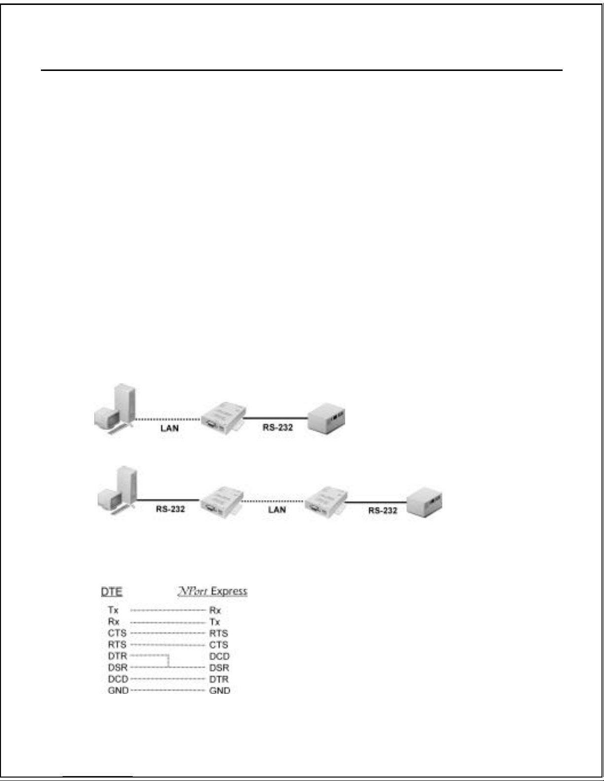
Application Architecture
Two typical applications:
(1)
(2)
. Note: If the DCD signal for carrier detection is required, you will need to use a cable to connect
NPort Express’s serial port to your device/PC, as shown here:
Page 2

2/4
NPort Express Configuration
. Note: This function is available in firmware version 1.01.81 or above for NPort Express
1. Enter NPort Express’s configuration screen using either Telnet over a LAN, or Moxa PComm
Terminal Emulator via NPort Express’s RS-232 Console port.
2. Open the “serverConfig” screen, and then change the “Operating Mode” to [Ethernet Modem].
3. Open the “Serialport” screen and set “TCP port no.” and “Destination IP”.
NOTES: 1. “TCP port no.” has default value = 4001
2. Only the device with IP set to “Destination IP” will be allowed access or leave empty for
all devices
4. Restart NPort Express’s operating system.
Using Ethernet Modem
[Dial-in]
NPort Express listens for a TCP/IP connection request from the remote Ethernet modem or host. NPort
Express’s response depends on the ATS0 value, as outlined below.
ATS0=0 (default): NPort Express will temporarily accept the TCP connection and then send the “RING”
signal out through the serial port. The serial controller must reply with “ATA” within
2.5 seconds to accept the connection request, after which NPort Express enters data
mode. If no “ATA” command is received, NPort Express will disconnect after
sending three “RING” signals.
ATS0>=1: NPort Express will accept the TCP connection immediately and then send the
“CONNECT <baud>” command to the serial port, in which <baud> represents the
baud rate of NPort Express’s serial port. After that, NPort Express immediately enters
data mode.
[Dial-out]
NPort Express accepts the AT command “ATD <IP>:<TCP port>” from the serial port and then requests a
TCP connection from the remote Ethernet Modem or PC. This is where <IP> is the IP address of the
remote Ethernet modem or PC, and <TCP port> is the TCP port number of the remote Ethernet modem or
PC. Once the remote box accepts this TCP connection, NPort Express will send out the “CONNECT
<baud>” signal via the serial port and then enter data mode.
[Disconnection request from local side]
When NPort Express is in data mode, the user can drive DTR signal to OFF or send the “+++” from local
serial port to NPort Express. NPort Express will enter the command mode and return the “NO
CARRIER” via serial port, and then input “ATH” for shot down tcp connection after 1 second.
Page 3

3/4
. Note: The “+++” cannot be divided, the “+” character can be changed in register S2 and the guard
time, which prefixes and suffixes the “+++” in order to protect the raw data, can be changed
in register S12.
[Disconnection request from remote side]
After the TCP connection is shot down by the remote Ethernet modem or PC, NPort Express will send the
“NO CARRIER” signal via serial port and return to command mode.
AT Commands Reference Info
NPort Express supports the following common AT commands used with a typical modem:
No. AT command Description Remarks
1 ATA Manually answer
2 ATD <IP>:<Port> Dial up the IP address & Port No.
3 ATE ATE0=Echo OFF
ATE1=Echo ON (default)
4 ATH ATH0=On-hook (default)
ATH1=Off-hook
5 ATI, ATI0, ATI1, ATI2 Modem version reply “OK” only
6 ATL Speaker volume option reply “OK” only
7 ATM Speaker control option reply “OK” only
8 ATO On line command
9 ATP, ATT Set Pulse/Tone Dialing mode reply “OK” only
10 ATQ0, ATQ1 Quiet command (default=ATQ0)
11 ATSr=n Change the contents of S register See “S registers”
12 ATSr? Read the contents of S register See “S registers”
13 ATV Result code type
ATV0 for digit code,
ATV1 for text code
0=OK
1=connect (default)
2=ring
3=No carrier
4=error
14 ATZ Reset (disconnect, enter command mode and restor
e
the flash settings)
Page 4

4/4
15 AT&C Serial port DCD control
AT&C0=DCD always on
AT&C1=DTE detects connection by DCD on/off
(default)
16 AT&D Serial port DTR control
AT&D0=recognize DTE always ready (default)
AT&D1, AT&D2=reply DTE when DTR On
17 AT&F Restore manufacturer’s settings
18 AT&G Select guard time reply “OK” only
19 AT&R Serial port RTS option command reply “OK” only
20 AT&S Serial port DSR control reply “OK” only
21 AT&V View settings
22 AT&W Write current settings to flash for next boot up
S Registers
No. S Register Description & default value Remarks
1 S0 Ring to auto-answer (default=0)
2 S1 Ring counter (always=0)
no action applied
3 S2 Escape code character (default=43 ASCII “+”)
4 S3 Return character (default=13 ASCII)
5 S4 Line feed character (default=10 ASCII)
6 S5 Backspace character (default= 8 ASCII)
7 S6 Wait time for dial tone (always=2, unit=sec)
no action applied
8 S7 Wait time for carrier (default=3, unit=sec)
9 S8 Pause time for dial delay (always=2, unit=sec)
no action applied
10 S9 Carrier detect response time
(always=6, unit 1/10 sec)
no action applied
11 S10 Delay for hang up after carrier
(always=14, unit 1/10 sec)
no action applied
12 S11 DTMF duration and spacing (always=100 ms)
no action applied
13 S12 Escape code guard time
(default=50, unit 1/50 sec)
to control the idle time for “+++”
 Loading...