

Page 1
– 1 – – 2 – – 3 –
P/N: 1802003114401
NPort DE-311
Quick Installation Guide
Fifth Edition, June 2014
OVerview
Welcome to Moxa’s NPort Express DE-311, a compact palm-sized
data communication device that allows you to control
RS-232/422/485 s erial devices ov e r a T CP/IP based Ethernet
network.
Package Checklist
Before installing the DE-311, verify that the package contains the
following item s :
• NPort DE-311 universal serial device server
• NPort Express Quick Installation Guide for the DE-311
• NPort Documentation & Software CD
• Mini adapter
Optional Accessories
• DK-35A (for 35 mm DIN-rail, includes 4 screws)
Please notify your sales rep res enta ti ve i f any of t he ab ov e item s i s
missing or damaged.
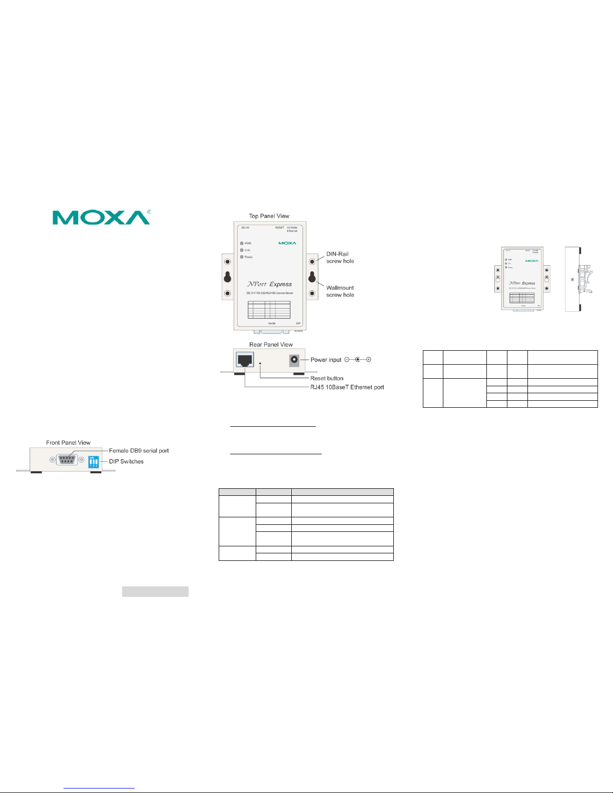
Hardware Introduction
Reset Button—Hold the reset button down to erase the password
or load the factory defaults, depending on how long the button is
held down:
• 3 seconds to erase the password
The ready LED will flash every half-second when the password
has been erased. You may release the reset button at this
time.
• 10 seconds to load factory defaults
The ready LED will flash five times every second when the
factory defaults have been loaded. You may release the reset
button at this time.
LED Indicators—There ar e three LED ind icators o n the top panel :
LED Name
LED Color
LED Function
PWR
red
Power is on
off
Power is off, or power error condition
exists
Link
orange
10 Mbps Ethernet connection
green
100 Mbps Ethernet connection
off
Ethernet cable is disconnected, or has
a short
Ready
green
System is ready
off
System error
Hardware Installation
Placement Option s
You may place the unit
on a desktop or other
horizontal surface. You
may also make use of
the DIN
-rail or wall
mount options, as
illustrated here .
Wall Mount
DIN-Rail
DIP Switch
The top panel contains the following table, which explains the DIP
switch settings for the serial port. The DIP swi tches are located at
the rear panel.
SW1
Serial
Connection
SW2 SW3 Interface Mode
ON
RS-232
Console
--- --- ---
OFF
Data
Comm
OFF
OFF
RS-232
OFF
ON
RS-422
ON
OFF
2-wire RS-485 by RTS
ON
ON
2-wire RS-485 by ADDC
SW1 is used to activate the serial console. When SW1 has been
changed, the unit will reboot to initialize the new setting. You w il l
need to wait for the green Ready LED to tur n off and th en on again ,
which indicates that serial console mode has been activated or
deactivated. SW2 and SW3 are used to select the serial port
interface. (Note that RTS stands for Ready To Send and ADDC
stands for Automatic Data Direction Control.)
When adjustin g the DIP switches, p le a s e keep the following in
mind:
• To use the serial port as an RS-232 console connection, such
as when using MOXA PComm Terminal Emulator or
HyperTerminal, set SW1 to the ON.
• Some configuration may be carried out through a Telnet
connection, du ring which da ta is transmi tted throug h the unit’s
Ethernet port. SW1 must be OFF in order for the unit to
establish a Telnet connection.
Software Installation Information
Detailed instructions for installing the included software can be
found on the NPort Documentation & Software CD in the “NPort
Family Software Installation Guide.”
Page 2
– 4 – – 5 – – 6 –
www.moxa.com/support
The Americas:
+1-714-528-6777 (toll-free: 1-888-669-2872)
Europe:
+49-89-3 70 03 99-0
Asia-Pacific:
+886-2-8919-1230
China:
+86-21-5258-9955 (toll-free: 800-820-5036)
2014 Moxa Inc. All rights reserved.
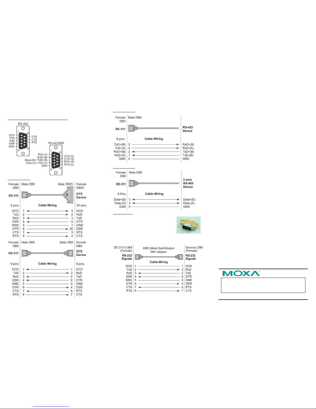
Pin Assignments and Cable Wiring
Female DB9 Connector Pi n Assignments
RS-232 Wiring
RS-422 Wiring
RS-485 Wiring
Mini Adapter
The NPort
Express DE-311 accepts devices
with both male and female connectors. A
D
-shell female serial connector is built-
in, and
a DB9 male null-modem adapter is included as
a standard accessory.
If you wish to make your own DB9 to DB9 null-modem (or
cross-over) cable, the pinouts are as follows:
Environmental Specifications
Power requirements
DC 9V to 30V, 300 mA at 9V
Operating temp.
0 to 55◦C
Operating humid it y
5 to 95% RH
Dimensions (W×D×H)
90 × 100.4 × 22 mm
3.54 × 3.95 × 0.87 inch
(including ears)
67 × 100.4 × 22 mm
2.64 × 3.95 × 0.87 inch
(without ears)
Surge protection
15 KV ESD for serial port
Magnetic isolation
1.5 KV for Ethernet
Regulatory approvals
FCC B, CE B, UL, CUL, TUV
 Loading...