

Page 1
– 1 – – 2 – – 3 –
P/N: 1802066500013
NPort 6600 Series
Quick Installation Guide
Fifth Edition, March 2011
1. Overview
The NPort 6600 series of serial device servers includes 8-port,
16-port, and 32 -port models for connecting larger numbers of
serial devices t o Ethernet. Some applications now also require
better security when transmitting data through a network. The
NPort 6600 series of device servers use DES, 3DES, and AES data
encryption to provide secure network communication.
2. Package Checklist
Before Installing your NPort 6600 series secure device server,
verify that the package contains the following items:
• 1 NPort 6600 device server
• CBL-RJ45M9-150: 8-pin RJ45 to DB9 male connection cable,
150 cm
• Power Cord (AC models only)
• 2 rack-mount ears
• Documentation and software CD
• Quick installat ion guide (printe d)
• Warranty card
Optional Accessories
• DK-35A: 35 mm DIN-Rail Mounting Kit
• DIN-Rail Power Su pply
• NM-TX01/NM-TX01-T: Network module with one
10/100BaseTX Ethernet port (RJ45 connector; supports
cascade redundancy)
• NM-FX01-S-SC/NM-FX0 1-S-SC-T: Network module with one
100BaseFX sin gle mode fibe r port (SC conn ector; supports
cascade redundancy)
• NM-FX02-S-SC/NM-FX0 2-S-SC-T: Network module with two
100BaseFX sin gle mode fibe r ports (SC connector s; supports
cascade redundancy)
• NM-FX01-M-SC/NM-FX 01-M-SC-T: Network module with one
100BaseFX mult i mode fiber port (SC connector; supports
cascade redundancy)
• NM-FX02-M-SC/NM-FX 02-M-SC-T: Network module with t wo
100BaseFX mu lti mode fiber ports (SC connectors; supports
cascade redundancy)
• NM-GPRS/GSM: GPRS/GSM modem module
• NM-Modem/NM-Modem- T: One PSTN modem port with RJ11
connector
NOTE: Please notify your sales representative if any of the above
items is missing or damaged.
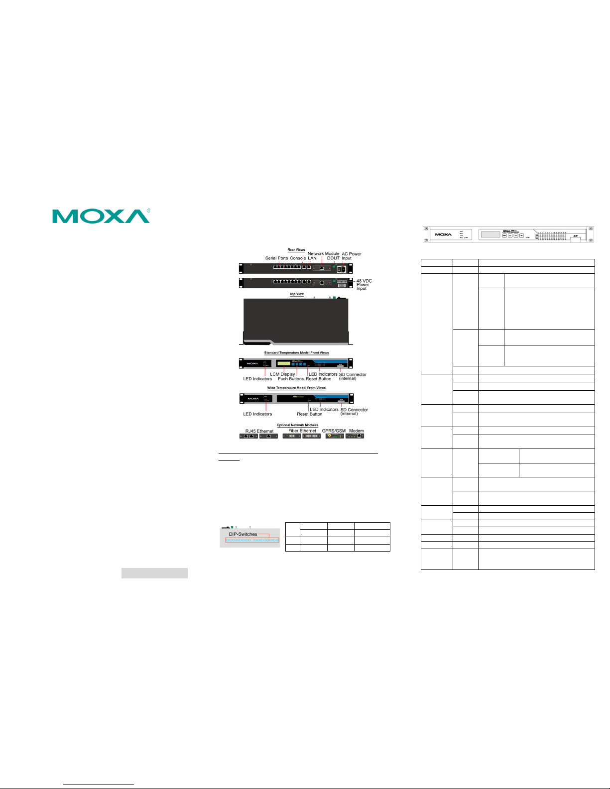
3. Hardware Introduction
Demonstrated 8 port model to be an example.
Reset button
Press the Reset button continuously for 5 sec to load factory
defaults
Adjustable pull high/low resistor for RS-485 (150 KΩ or 1
K
Ω)
The NPort 6650 has 3 DIP Switches associated with each serial port
for configuring the pull high/low resistors for RS-485 applicatio ns.
The switches are located in a recess on the bottom of the NPort
6650. To access the switches, first remove the panel covering the
recess.
: Use a pointed object to press the reset button. Release
the button after the Ready LED stops blinking.
SW 1 2 3
Pull High Pull Low Terminator
ON 1 KΩ 1 KΩ 120 KΩ
OFF
150 KΩ
150 KΩ
---
NOTE: For RS -232 applications, all DIP Switches for the port
should be set to the OFF position.
Rack Mounting
Use four screws to attach the NPort 6610/6650 to a standard rack
LED Indicators
Name Color Function
PWR Red Power is being supplied to the power input.
Ready Red Steady
on:
Power is on and the NPort 6600
series is booting up.
Blinking:
IP conflict, DHCP or BOOTP server
not responding, or relay output.
Check relay output first. If still
blinking, then there is an IP
conflict, or the DHCP or BOOTP
server did not respond properly.
Green Steady
on:
Power is on and the NPort 6600
series is fu nctioning norma lly.
Blinking: The device server has been
located by the Administrator’s
Locator function.
Off Power is off, or power error condition exists.
Link Orange 10 Mbps Ethernet connection.
Green 100 Mbps Ethernet con nection.
Off Ethernet cable is disconnected, or has a
short.
P1-P16 Tx Green Seria l port is transmitting data.
Off No data is being transmitted through the
serial port
P1-P16 Rx Orange Serial port is re ceiving data..
Off
No data is being received through the serial
port.
FX Orange Steady on: Ethernet fiber connection,
but port is idle.
Blinking: Fiber port is transmitting or
receiving data .
P1-P16
in-use
LEDs
Green Serial port is opened by server side
software.
Off Serial port is not opened by server side
software.
Alarm Red The relay Dout is open (exception)
Off The relay Dout is Shorted (normal)
Module Green Network module is plugged in and detected
Off No module present
GSM Green GSM Connection
GPRS Orange G PRS Connection
GPRS/GSM
Signal
Strength
Green More LEDs indicates better signal; 4 LEDs
indicates maxim um signal strength.
Page 2
– 4 – – 5 – – 6 –
www.moxa.com/support
The Americas: +1-714-528-6777 (toll-free: 1-888-669-2872)
Europe:
+49-89-3 70 03 99-0
Asia-Pacific: +886-2-8919-1230
China:
+86-21-5258-9955 (toll-free: 800-820-5036)
2010 Moxa Inc., All Rig hts Reserve d
LCM Display Panel
The NPort 6600 display pan el will show the model name, serv er
name, and IP address when powered up
N P 6 6 1 0 _ 6 6 1 0 2
1 9 2 . 1 6 8 . 1 2 7 . 2 5 4
Operating the LCM Panel
There are four push buttons on the NPort 6600’s top panel for
operating the server’s LCM panel. The function of each button is
described be low:
Button Action
MENU Activates the main menu, or returns to a lower level.
∧
Scrolls up through a list of items shown on the LCM panel’
s
second line.
∨
Scrolls down through a list of items shown on the LCM
panel’s second line.
SEL Selects the option listed on the LCM panel’s second line.
Detailed LCM pan el operating instructions can be found on the
Document and Software CD in the “NPort 6600 Ser ies User’s
Manual.”
Note: LCM display panel and push buttons only for standard
temprature model
4. Hardware Installation Procedure
STEP 1: Connect the NPort 6600 device server to a suitable power
source.
AC models: C onnect the 100 to 240 VAC power cord to the NPort
6600’s power input.
DC models
STEP 2: Con nect the NP ort 6600 se ries to a network. Use a
standard straight-through Ethernet cable to connect to a hub or
switch. Use a cross-over Ethernet cable when connecting to your
computer’s Ethernet port (e.g., when setting up or testing the
NPort 6600 server).
: Connect the terminal block to a battery.
STEP 3: Con nect the NPort 6600’ s serial ports to your serial
devices.
5. Software Installation Information
NPort Search Utility
To install the NPort Search Utility, insert the NPort Document and
Software CD into your computer’s CD-ROM dr ive. When the NPort
Installation CD window opens, click on the Installation button, and
then follow the instructions on the screen. To view detailed
information about the NPort Search Utility, refer to the pdf version
of the “NPort 6600 Series User’s Manual,” which is located in the
document directory of the CD.
PComm Lite and Console Port (19200, 8, None, 1)
MOXA’s PComm Lite software utility is also includ ed in the
Document and Softwa re CD o f the CD-ROM. PComm Lite is often
used to connect to the NPort 6600 through its console port to
configure the IP address for the first time. Use the following serial
console parameters when connecting through the console port:
19200, 8, None, 1.
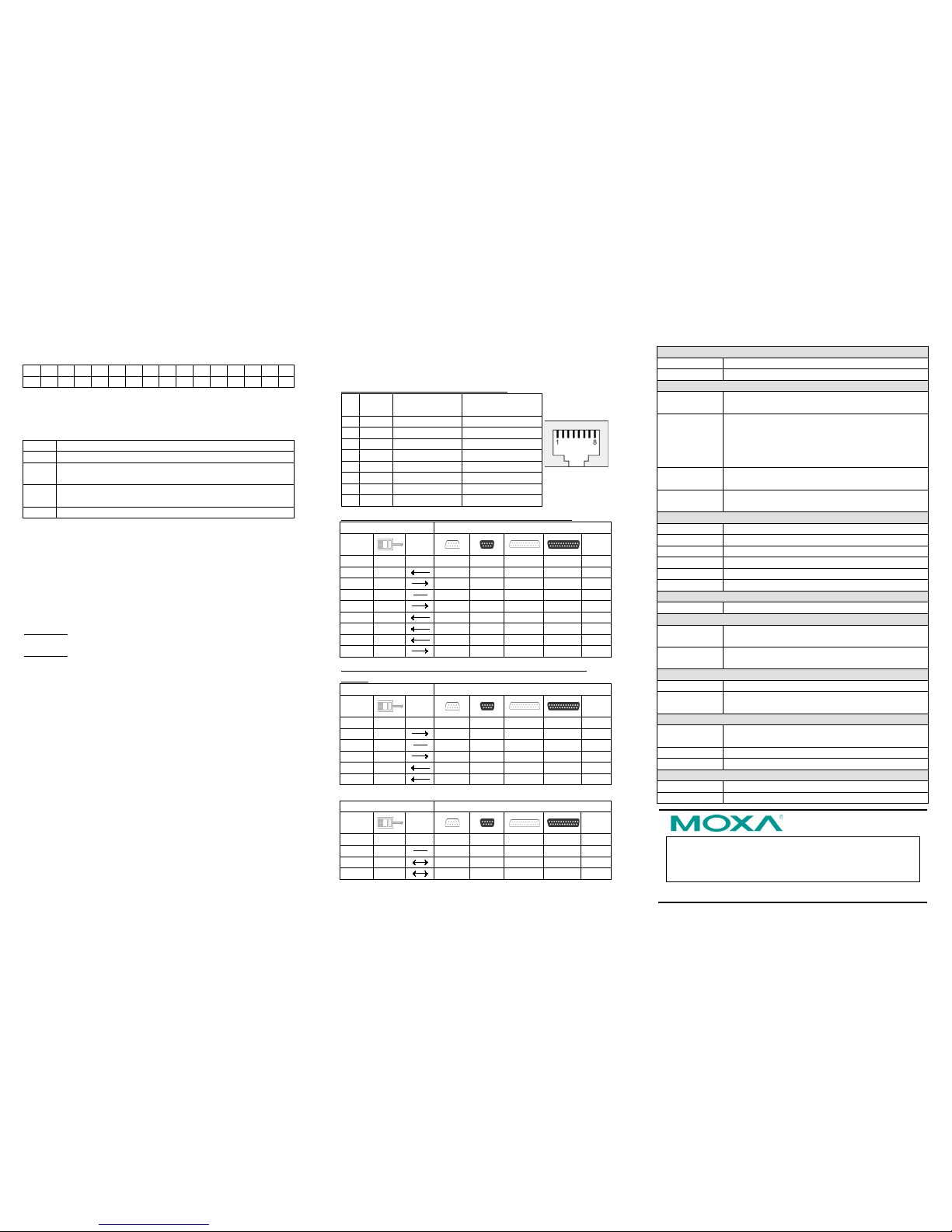
6. Pin Assignments and Cable Wiring
Pin
Pin Assignments (NPort 6610/6650)
RS-232
RS-422,
4-wire RS -485
2-wire RS-485
1 DSR --- --2 RTS T xD+ --3 GND G ND GND
4 TxD TxD - --5 RxD RxD+ Data+
6 DCD RxD- Data7 CTS --- --8 DTR --- ---
NPort6610/6650
Pin Mapping for RS-232 Cables (NPort 6610/6650)
Serial Device
RJ45 DB9(M) DB9(F) DB25(M) DB25 (F)
DSR 1
6 4 6 20 DTR
RTS 2
7 8 4 5 CTS
GND 3
5 5 7 7 GND
TxD 4
3 2 2 3 RxD
RxD 5
2 3 3 2 TxD
DCD 6
1 1 8 8 DCD
CTS 7
8 7 5 4 RTS
DTR 8
4 6 20 6 DSR
NPort 6650
Pin Mapping for RS-422/4-wire R S-485 Cables (NPort
6650)
Serial Device
RJ45 DB9(M) DB9(F) DB25(M) DB25(F)
TxD+ 2
7 8 4 5 RxD+
GND 3
5 5 7 7 GND
TxD- 4
3 2 2 3 RxD-
RxD+ 5
2 3 3 2 TxD+
RxD- 6
1 1 8 8 TxD -
Pin Mapping for 2-wire RS-485 Cables (NPort 6650)
NPort 6650 Serial Device
RJ45 DB9(M) DB9(F) DB25(M) DB25(F)
GND 3
5 5 7 7 GND
Data+ 5
2 3 3 2 Data+
Data- 6
1 1 8 8 Data-
7. Specifications
LAN
Ethernet Ports: 10/100 Mbps (RJ45)
Protection: Built-in 1.5 KV magnetic isola tion
Serial Interface
NPort 6610:
NPort 6650:
8, 16, or 32 RS-232 ports (8-pin RJ45)
8, 16, or 32 RS-232/422/485 ports (8-pin RJ45)
Signals: RS -232: TxD, RxD, RTS, CTS, DTR, DSR, DCD,
GND
RS-422: Tx+, Tx-, Rx+, Rx-, GND
RS-485(2W): Data+, Data-, G ND
RS-485(4W): Tx+, Tx-, Rx+, Rx-, GND
Serial Line
Protection: 15 KV ESD for all s ignals
RS-485 Data
Direction:
ADDC™ (Automatic Data Direction Control)
Serial Communication Parameters
Parity: None, Even, Odd, Space, Mark
Data bits: 5, 6, 7, 8
Stop bit(s): 1, 1.5, 2
Flow control: RTS/CTS, XON/XOFF, DTR/DSR
Speed: 50 bps to 921.6 Kbps
Console port: RS-232 console × 1
Memory Expansion Slot
Slot Type: SD socket (supports up to 2 GB)
Power Requirements
Power input: 100 to 240 VAC, 47 to 63 Hz,
±48 VDC (20 to 72 VDC, -20 to -72 VDC)
Alarm Contact:
Relay output with current carrying capacity of 1A
@ 24 VDC
Mechanical Specifications
Material: SECC sheet metal (1 mm)
Dimensions:
(W×D×H)
480×44×195 mm (including ears)
440×44×195 mm (without ears)
Environment
Operating
Temp.:
0-55°C (32 to 131°F), 5 to 95% RH
Wide Temp.: -40 to 75°C (-40 to 167°F)
Storage Te mp.: -40 to 75°C (-40 to 167°F)
Regulatory Approvals
EMC: FCC Class A, CE Class A
Safety: UL, CUL, EN 60950 -1
 Loading...