

Moxa Technologies NPort 5630-16, NPort 5610-16, NPort 5610-16-48V, NPort 5630-8, NPort 5610-8-48V User Manual
...Page 1

NPort 5600 Series User’s Manual
Fifteenth Edition, September 2014
www.moxa.com/product
© 2014 Moxa Inc. All rights reserved.
Page 2

NPort 5600 Series User’s Manual
Moxa Americas
Toll
Tel:
Fax:
Moxa China (Shanghai office)
Toll
Tel:
Fax:
Moxa Europe
Tel:
Fax:
Moxa Asia
Tel:
Fax:
Moxa India
Tel:
Fax:
The software described in this manual is furnis he d under a license agre e ment and may be used only in accordance with
the terms of that agreement.
Copyright Notice
© 2014 Moxa Inc. All rights reserved.
Trademarks
The MOXA logo is a registered trademark of Moxa Inc.
All other trademarks or registered marks in this m anual be long to the ir res pec tive manufacturers.
Disclaimer
Information in this document is subject to cha nge witho ut no tic e and doe s no t repres e nt a commitme nt o n the part of
Moxa.
Moxa provides this document as is, without warranty of any kind, either expressed or implied, including, but not limited
to, its particular purpose. Moxa reserves the rig ht to make improvements and/or changes to this manual, or to the
products and/or the programs described in this manual, a t any time .
Information provided in this manual is intended to be accurate and reliable. However, Moxa assumes no responsibility for
its use, or for any infringements on the rights of third parties that m ay res ult fr om its use.
This product might include unintentional tec hnic a l o r typographical errors. Changes are periodically m ade to the
information herein to correct such errors, and these changes are incorporated into new editions of the public ation.
Technical Support Contact Information
www.moxa.com/support
-free: 1-888-669-2872
+1-714-528-6777
+1-714-528-6778
+49-89-3 70 03 99-0
+49-89-3 70 03 99-99
+91-80-4172-9088
+91-80-4132-1045
-free: 800-820-5036
+86-21-5258-9955
+86-21-5258-5505
+886-2-8919-1230
-Pacific
+886-2-8919-1231
Page 3

Table of Contents
1. Introduction ...................................................................................................................................... 1-1
Overview ........................................................................................................................................... 1-2
Package Checklist ............................................................................................................................... 1-2
Product Features ................................................................................................................................ 1-2
Product Specifications ......................................................................................................................... 1-3
2. Getting Star ted.................................................................................................................................. 2-1
Panel Layout ...................................................................................................................................... 2-2
Connecting the Ha r dware..................................................................................................................... 2-2
Desktop ............................................................................................................................................. 2-2
Rackmount ........................................................................................................................................ 2-3
Wiring Requirements ................................................................................................................... 2-3
Connecting NPort 5600 VAC’s Power .............................................................................................. 2-3
Connecting NPort 5600 VDC’s Power .............................................................................................. 2-4
Grounding NPort 5600 VDC .......................................................................................................... 2-4
Connecting to the Network ........................................................................................................... 2-4
Connecting to a Serial Device ....................................................................................................... 2-4
LED Indicators ............................................................................................................................ 2-4
Link Indicator on the Rear Panel of NPort 5650 Fiber Model .............................................................. 2-5
Real Time Clock .......................................................................................................................... 2-5
Adjustable Pull High/low Resistors for the RS-485 Port ..................................................................... 2-5
3. Initial IP Address Configuration ........................................................................................................ 3-1
Initializing NPort’s IP Addres s ............................................................................................................... 3-2
Factory Default IP Address ................................................................................................................... 3-2
LCM Display ....................................................................................................................................... 3-2
NPort Administration Suite ................................................................................................................... 3-5
ARP................................................................................................................................................... 3-5
Telnet Console ................................................................................................................................... 3-6
4. Choosing the Proper Operation Mode ................................................................................................ 4-1
Overview ........................................................................................................................................... 4-2
Real COM Mode .................................................................................................................................. 4-2
TCP Server Mode ................................................................................................................................ 4-3
TCP Client Mode ................................................................................................................................. 4-3
UDP Mode .......................................................................................................................................... 4-4
Pair Connection Mode .......................................................................................................................... 4-4
Reverse Telnet Mode ........................................................................................................................... 4-4
Disabled Mode .................................................................................................................................... 4-5
RFC2217 Mode ................................................................................................................................... 4-5
PPP Mode ........................................................................................................................................... 4-5
5. Web Console Configuration ............................................................................................................... 5-1
Opening Your Browser ......................................................................................................................... 5-2
Basic Settings .................................................................................................................................... 5-3
Time .......................................................................................................................................... 5-4
Console ...................................................................................................................................... 5-4
Network Settings ................................................................................................................................ 5-5
SNMP Settings ............................................................................................................................ 5-7
IP Address Report ....................................................................................................................... 5-7
Serial Settings .................................................................................................................................... 5-8
Serial Parameters ........................................................................................................................ 5-9
Operating Settings ............................................................................................................................ 5-10
Real COM Mode ......................................................................................................................... 5-10
TCP Server Mode ....................................................................................................................... 5-13
TCP Client Mode ........................................................................................................................ 5-16
UDP Mode ................................................................................................................................ 5-19
Pair Connection Mode ................................................................................................................ 5-21
Pair Connection Master Mode ...................................................................................................... 5-21
Pair Connection Slave Mode ........................................................................................................ 5-22
Reverse Telnet Mode ................................................................................................................. 5-23
Disabled Mode .......................................................................................................................... 5-24
RFC2217 Mode .......................................................................................................................... 5-24
PPP Mode ................................................................................................................................. 5-26
Accessible IP Settings........................................................................................................................ 5-27
PPP User Table ................................................................................................................................. 5-28
Auto Warning Settings ....................................................................................................................... 5-28
Auto warning: E-mail and SNMP Trap ........................................................................................... 5-28
Event Type ............................................................................................................................... 5-29
Monitor............................................................................................................................................ 5-31
Monitor Line ............................................................................................................................. 5-31
Page 4

Monitor Async ........................................................................................................................... 5-31
Monitor Async-Settings .............................................................................................................. 5-31
Change Password ............................................................................................................................. 5-32
Load Factory Defaults ........................................................................................................................ 5-32
6. Configuring NPort Administrator ....................................................................................................... 6-1
Overview ........................................................................................................................................... 6-2
Installing NPort Administrator .............................................................................................................. 6-2
Configuration ..................................................................................................................................... 6-5
Broadcast Search ........................................................................................................................ 6-6
Unlock Password Protection .......................................................................................................... 6-7
Configuring NPort 5600 .............................................................................................................. 6-10
Upgrading Firmware .................................................................................................................. 6-12
Export/Import ........................................................................................................................... 6-13
Monitor............................................................................................................................................ 6-14
Port Monitor ..................................................................................................................................... 6-19
COM Mapping ................................................................................................................................... 6-19
On-line COM Mapping ................................................................................................................ 6-20
Off-line COM Mapping ................................................................................................................ 6-23
IP Location ....................................................................................................................................... 6-24
7. NPort CE Driver Manager for Windows CE ......................................................................................... 7-1
Overview ........................................................................................................................................... 7-2
Installing NPort CE Driver Manager ....................................................................................................... 7-2
Using NPort CE Driver Manager ............................................................................................................ 7-2
8. IP Serial LIB ...................................................................................................................................... 8-1
Overview ........................................................................................................................................... 8-2
IP Serial LIB Function Groups ............................................................................................................... 8-2
Example Program ............................................................................................................................... 8-3
A. Pinouts and Cable Wiring .................................................................................................................. A-1
Port Pinout Diagrams .......................................................................................................................... A-2
Ethernet Port Pinouts ................................................................................................................... A-2
Serial Port Pinouts ....................................................................................................................... A-2
Cable Wiring Diagrams ........................................................................................................................ A-3
Ethernet Cables........................................................................................................................... A-3
Serial Cables for NPort 5610/5650 (RS-232) ................................................................................... A-3
Serial Cables for NPort 5630 (RS-422/4-wire RS-485) ...................................................................... A-5
Serial Cables for NPort 5630 (2-wire RS-485) ................................................................................. A-6
Serial Cables for NPort 5650 (RS-422/4-wire RS-485) ...................................................................... A-7
Serial Cables for NPort 5650 (2-wire RS-485) ................................................................................. A-8
Pin Assignments for DB9 and DB25 Connectors ............................................................................... A-9
B. Well Known Port Numbers ................................................................................................................ B-1
C. SNMP Agent with M IB II & RS-2 32 Lik e Group .................................................................................. C-1
D. Auto IP Report Protocol .................................................................................................................... D-1
E. Compliance Notice ............................................................................................................................. E-1
Page 5

1
1. Introduction
Moxa’s NPort 5600 advanced serial device serv ers make it easy to networ k-enable your serial devices. The
NPort 5600 Series includes 14 models: NPort 5610-8, NPort 5610-8-48V, NPort 5610-16, NPort 5610-16-48V,
NPort 5630-8, NPort 5630-16, NPort 5650-8, NPort 5650-8-T, NPo rt 5650-16, NPort 5650-16-T, NPort
5650-8-M-SC, NPor t 5 650-8-S-SC , NPort 5 650-16-M-SC, NPort 5650-16-S-SC, NPort 5650-8-HV-T, NPort
5650-16-HV-T. In this manual, we often refer to the fifteen products collectively as “5600” or “5600 Series.”
The following topics are covered in this chapter:
Overview
Package Checklist
Product Features
Product Specifications
Page 6

NPort 5600 Series Introduction
1-2
•
RJ45 8
•
RJ45 8
•
RJ45 8
•
RJ45 8
Overview
The NPort 5600 Series serial device servers are designed to make your industrial serial devices Internet ready
instantly. The rack-mounted size of the NPort 5600 device servers makes them the ideal choice for connecting
your RS-232 (NPort 5610-16/8), RS-422/ 485 (NPort 56 30-16/8), or RS-23 2/422/485 (N Port 5650-16/8) serial
devices—such as PLCs, m eters, and sensors—to an IP-based Ethernet LAN, making it possible for your software
to access serial devices anywhere over a local LAN or the Internet.
The NPort 5600 serial device servers ensure the compatibility of network software that uses a standard network
API (Winsock or BSD Sockets) by providing TCP Server Mode, TCP Client Mode, and UDP Mode. And thanks to
NPort’s Real COM/TTY drivers, software that works with C OM/TTY p orts can be set up to work over a TCP/IP
network in no time. This excellent feature preserves your software investment and lets you enjoy the benefits
of networking your serial devices insta ntly .
The NPort 5600 serial device servers support automatic IP configuration protocols (DHCP, BOOTP) and manual
configuration via NPort’s handy web browser console. Both methods ensure quick and effective installation, and
by using NPort 5600’s Windows Utility, installation is very straightforward, since all system parameters can be
stored and then copied to other device servers simultaneously.
Package Checklist
The Moxa NPort 5600 Series products are shipped with the following items:
Standard Accessories
• 1 8- or 16-port serial device server
• Power cord (AC models only)
• NPort Documentation & Software CD
• NPort 5600 Quick Installation Guide
Optional Accessories
CBL-RJ45M9-150
CBL-RJ45F9-150
CBL-RJ45M25-150
CBL-RJ45F25-150
NOTE: Notify your sales representative if any of the above items is miss ing or damag ed.
Product Features
The NPort 5600 Series products have the following fe atures:
• Make your serial devices Internet ready
• Easy-to-use LCM (Liquid Crystal Module) interf ac e for setting up the IP address (does not apply to wide
temperature models)
• Versatile socket operatio n modes , inc luding TCP Server, TCP Client, and UDP
• Easy-to-use Windows Utility for mass installation
• Supports 10/100 Mbps Ethernet—auto-detectable
• Supports 16/8-port RS-232 or RS-422/485 interface or RS-232/422/485 interface
• Supports SNMP MIB-II for network management
-pin to DB9 Male cable, 150 cm
-pin to DB9 Female cable, 150 cm
-pin to DB25 Male cable, 150 cm
-pin to DB25 Female cable, 150 cm
Page 7

NPort 5600 Series Introduction
1-3
Ethernet Interface
Number of Ports:
Speed:
Connector:
Magnetic Isolat ion P ro tec t i o n:
Optical Fiber Interface (for -M-SC and -S-SC)
RX Sensitivity
-32 dBm
-34 dBm
Serial Interface
Number of Ports:
Serial Standards:
NPort 5610: RS
NPort 5630: RS
NPort 5650: RS
Connector:
RS
Pull High/Low Resistor for RS
Serial Communication Pa ra me te rs
Data Bits:
Stop Bits:
Parity:
Flow Control:
Baudrate:
Serial Signals
RS
RS-422: Tx+, Tx-, Rx+ , Rx-, GND
RS
RS
Software
Network Protocols: ICMP, IPv4, TCP, UDP, DHCP, BOOTP, Telnet, DNS, SNMP V1, HTTP, SMTP, SNTP, ARP,
PPP, SLIP, RTelnet, RFC2217
Configuration Options:
Windows Real COM
(x86/x64), Windows 2008 R2/2012/2012 R2 (x64), Windows Embedded CE 5.0/6.0, Windows XP Embedded
Fixed TTY Drivers:
eeBSD, AIX 5.x,
HP
Linux Real TTY Drivers:
Product Specifications
1
10/100 Mbps, auto MDI/M DIX
8-pin RJ45
1.5 kV built-in
100BaseFX
Multi-mode Single-mode
Wavelength 1300 nm 1310 nm
Max. TX -14 dBm 0 dBm
Min. TX -20 dBm -5 dBm
Link Budget 12 dB 29 dB
c
Typical Distance 5 km a
Saturation -6 dBm -3 dBm
a. 50/125 µm, 800 MHz*km fiber optic cable
b. 62.5/125 µm, 500 MHz*km fiber optic cable
c. 9/125 µm, 3.5 PS/(nm*km) fiber optic cable
4 km
b
40 km
8 or 16
-232
-422/485
-232/422/485
RJ45 (8 pins)
-485 Data Direction Control: ADDC® (automatic data direction control)
-485: 1 kΩ, 150 kΩ (NPort 5650-8/16)
5, 6, 7, 8
1, 1.5, 2
None, Even, Odd, Space, Mark
DSR/DTR and RTS/CTS (RS-232 only), XON/XOFF
50 bps to 921.6 kbps
-232: TxD, RxD, RTS, CTS, DTR, DSR, DCD, GND
-485-4w: Tx+ , Tx-, Rx+, Rx-, GND
-485-2w: Data+, Data-, GND
Web Console, Telnet Console, Windows Utility
Drivers: Windows 95/98/ME/NT/2000, Windo ws X P/200 3/Vista/2008/7/8/8.1
SCO Unix, SCO OpenServer, UnixWare 7, QNX 4.25, QNX 6, Solaris 10, Fr
-UX 11i, Mac OS X
Linux 2.4.x, 2.6.x, 3.x
Page 8

NPort 5600 Series Introduction
1-4
Mini Screen with P ush Buttons (for standard temp. models)
LCD Panel:
Push Buttons:
Physical Characteristics
Housing:
Weight:
NPort 5610
NPort 5610
NPort 5630
NPort 5650
NPort 5610
NPort
NPort 5630
NPort 5650
NPort 5650
NPort 5650
NPort 5650-16-HV-T: 3820 g
Dimensions:
Without ears: 440 x 45 x 198 mm (17.32 x 1.77 x 7.80 in)
With ears: 480 x 45 x 198 m
Environmental Limits
Operating Temperatur e:
Standard Models: 0 to 55°C (32 to 131°F)
Wide Temp. Models:
High Voltage Wide Temp. Models:
Storage Temperature:
Standard
Wide Temp. Models:
High Voltage Wide Temp. Models:
Ambient Relative Humidity:
Altitude:
Note: Please contact Moxa if you requ
Power Requirements
Input Voltage:
NPort 5610/5630/5650: 1 00 to 240 VAC, 47 to 63 hz
NPort 5610
NPort 5650
Power
NPort 5610
NPort 5630
NPort 5610
NPort 5650
NPort 5650
NPort 5650
NPort 5650
Liquid Crystal Display on the case
Four push buttons for convenient on-site configur ation
Metal
-8: 3340 g
-8-48V: 3160 g
-8, 5650-8-S-SC, 5650-8-M-SC: 3380 g
-8: 3360 g
-16: 3420 g
5610-16-48V: 3260 g
-16: 3400 g
-16: 3460 g
-16-S-SC, 5650-16-M-SC: 3440 g
-8-HV-T: 3720 g
m (18.90 x 1.77 x 7.80 in)
-40 to 75°C (-40 to 167°F)
-40 to 85°C (-40 to 185°F)
Models: -40 to 75°C (-40 to 167°F)
-40 to 75°C (-40 to 167°F)
-40 to 85°C (-40 to 185°F)
5 to 95% (non-condensing)
Up to 2000 m
ire products guaranteed to function properly at higher altitud e s .
-48V: ±48 VDC (20 to 72 VDC, -20 to -72 VDC)
-HV: 110 VDC (88 to 300 VDC)
Consumption:
-8/16: 141 mA @ 100 VAC, 93 mA @ 240 VAC
-8/16: 152 mA @ 100 VAC, 98 mA @ 240 VAC
-8/16-48V: 135 mA @ 48 VDC
-8/16: 158 mA @ 100 VAC, 102 mA @ 2 40 VAC
-8/16-S-SC: 164 mA @ 100 VA C , 110 mA @ 240 VAC
-8/16-M-SC: 174 mA @ 100 VAC, 113 mA @ 240 VAC
-8/16-HV: 152 mA @ 88 VDC, 86 mA @ 300 VDC
Page 9

NPort 5600 Series Introduction
1-5
Standards and Certifications
EMI:
EMS:
EN 61000
EN 61000
EN 61000
EN 61000
EN 61000
EN 61000
EN 61000
Safety:
EMC:
Medical:
Reliability
Automatic Reboot Trigger:
MTBF (mean time between fai lures):
NPort 5610
NPort 5610
NPort 5610
NPort
NPort 5630
NPort 5630
NPort 5650
NPort 5650
NPort 5650
NPort 5650
NPort 5650
NPort 5650
NP
NPort 5650
Warranty
Warranty Period:
Details:
EN55022 Class A, FCC part 15 Subpart B Class A
-4-2 ESD: contact 4 kV; air 8 kV
-4-3 RS: 3 V/m (80 MHz to 1 GHz)
-4-4 EFT: Power 4 kV; Signal 2 kV
-4-5 Surge: AC 1 kV (AC models); DC 2 kV (DC/HV models); Signal 1 kV
-4-6 CS: 3 V
-4-8
-4-11: AC models only
UL 60950-1, EN 60950 -1
55022/24
EN 60601-1-2 Class B, EN 55011
Built-in WDT (watchdog timer)
-8: 97,294 hrs
-16: 94,928 h rs
-8-48V: 96,758
5610-16-48V: 94,417 hrs
-8: 118,405 h rs
-16: 91,483 h rs
-8: 117,584 h rs
-16: 104,767 hrs
-8-S-SC: 116,9 14 hrs
-16-S-SC: 87,528 hrs
-8-M-SC: 116,914 hrs
-16-M-SC: 87,528 h rs
ort 5650-8-HV: 725,390 hrs
-16-HV: 531,264 hrs
See www.moxa.com/warranty
5 years
Page 10

2
2. Getting Started
This chapter includes information about ins talli ng NPort 5600 Series.
The following topics are covered in this chapter:
Panel Layout
Connecting the Hardware
Desktop
Rackmount
Wiring Requirements
Connecting NPort 5600 VAC ’s Power
Connecting NPort 5600 VDC ’s Power
Grounding NPort 5600 VDC
C o nne c ti ng to the Network
C o nne c ti ng to a Serial Dev i ce
LED Indicators
Link Indicator on the Rear Panel of NPort 5650 Fiber Model
R e a l Time Cl ock
A d j us table Pull High/low Resistors for the RS-485 Port
Page 11
NPort 5600 Series Getting Started
2-2
Panel Layout
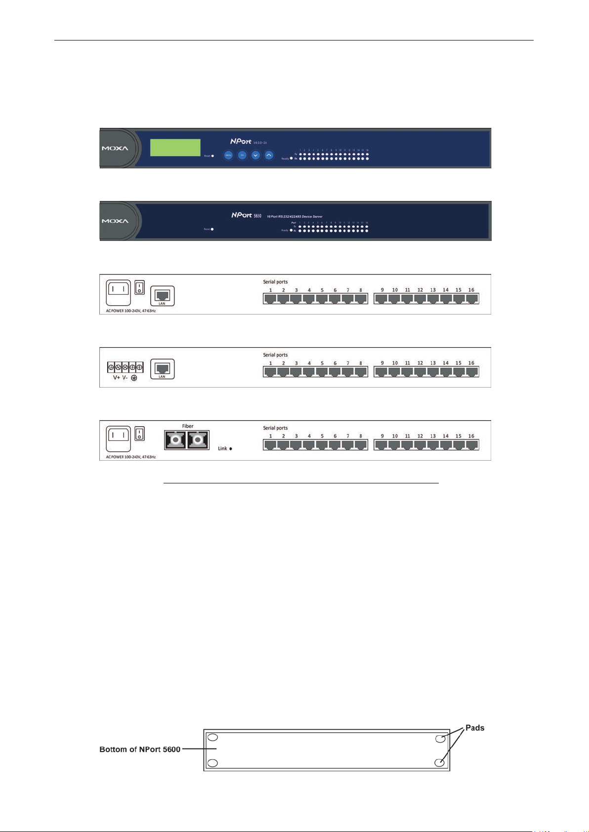
The following figures depict the front and rear panel s of the NPor t 5600 series.
Front panel of NPort 5600 series
Front panel of NPort 5600-T series
Rear panel of NPort 5600 series (AC Power)
Rear panel of NPort 5600 series (DC Power)
Rear panel of NPort 5650 Fiber model
Reset Button—Press the Reset button continuously for 5 sec to load factory defaults: U se a poi nte d obje c t,
such as a straightened paper clip or toothpick, to press the reset button. This will cause the Ready LED to blink
on and off. The factory defaults will be loaded once the Ready LED stop s blinking (after about 5 seconds). At
this point, you should release the reset button.
Connecting the Hardware
This section describes how to connect NPort 5600 Series to ser ial dev ices for firs t time testing p urp o se s. We
cover Wiring Requirements, Connecting NPort 5600 VAC’s Power, Connecting NPort 5600 VDC’s
Power, Grounding NPort 5 600 VDC, Connecting to the Network, Connecting to a Serial Device, and
LED Indicators.
Desktop
Place your NPort 5600 on a clean, flat, well-ventilated desktop. For better ventilation, attach the 4 pads from
the desktop kit to the bottom of the unit, and leave som e space between the NPort 5600 and other equipment.
Do not place equipment or objects on top of the unit, as this might d amage the serv er.
Page 12
NPort 5600 Series Getting Started
2-3
ATTENTION
Safety First!
Be sure to disconnect the power
Wiring Caution!
Calculate the maximum possible curre nt in each power wire and com mon wire . Observe all elec trical codes
dictating the maximum current allowab le for ea c h wire siz e .
If the current
equipment.
Temperature Caution!
Please take care when handling NPort
heat, and consequently the casin
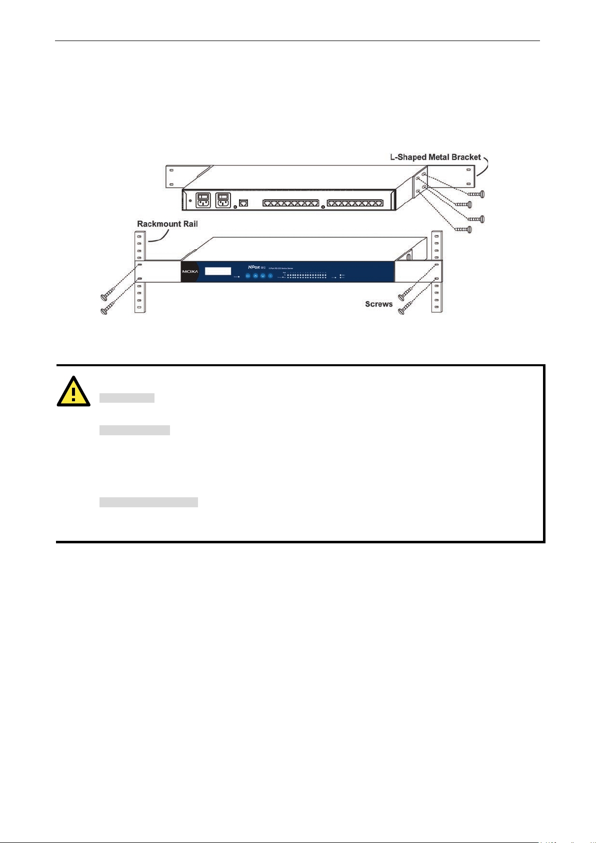
Rackmount
The NPort 5600 is designed to be mounted on a standard 19-inch rack. Use the enclosed pair of L-shaped metal
brackets and screws to fast en your NPort 5600 to the rack cabinet. Each L-shaped bracket has 6 holes, leaving
two outer or inner holes available for other uses . You have two options. You can lock either the front or rear
panel of the NPort 5600 to the front of the rack. Locking the front panel is shown in the following figure.
Wiring Requirements
You should also pay attention to the following po ints :
• Use separate paths to route wiring for power and devices . If power wir ing and devic e wir ing pa ths must
cross, make sure the wires are perpendicular at the intersection point.
NOTE: Do not run signal or communication wiring and power wiring in the same wire conduit. To avo id
interference, wires with different sig na l c haracteristics should be routed separately.
• You can use the type of signal transmitted through a wire to determine which wires should be kept separate.
The rule of thumb is that wiring that shares similar electrical characteristics can be bundled together .
• Keep input wiring and output wiring separate.
• Where necessary, it is strongly advised that you labe l wir ing to all devices in the system.
cord before installing and/or wiring yo ur NPort 56 0 0 Serie s.
goes above the maximum ratings, the wiring could overheat, causing serious damage to your
5600. When plugged in, NPort 5600’s internal components generate
g may feel hot to the touch.
Connecting NPort 5600 VAC’s Power
Connect NPort 5610/30/50-16/8’s 100-240 VAC power line with its AC connec tor . If the power is proper ly
supplied, the “Ready” LED will show a solid red color until the system is ready, at which time the “Ready” LED
will change to a green color.
Page 13

NPort 5600 Series Getting Started
2-4
s V+ terminal, and the power
terminal, and then tighten the
can still operate even if the DC and DC
NOTE
You should use 8 kg
’s
power cord to its terminal block.
T
he second conta ct
from the right of the 5
NPort 56
ATTENTION
This product is intended to be mounted to a well
The bottom right corner LED indicator
connected to a 100 Mbps Ethernet network.
The bottom left corner LED indicator maintains a solid orange color when the cable is properly
connected to a 10 Mbps Ethernet network.
Connecting NPort 5600 VDC’s Power
To connect NPort 5610-16/8-48V’s power cord with its terminal b lo c k, follow the steps given below:
Loosen the screws on the V+ and V- terminals of NPort 5600 VDC’s terminal block.
Connect the power cord’s VDC wire to the terminal block’
cord’s DC Power Ground wire to the terminal block’s Vterminal block screws. (Note: NPort 5600 VDC
Power Gro u n d are rever sed.)
If the power is properly supplied, the “Ready” LED will show a solid red color until the system is ready, at which
time the “Ready” LED will change to a green color.
-cm of screw torque and 22-14 AWG of suitable electric wire to connect NPort 5600-VDC
Grounding NPort 5600 VDC
Grounding and wire routing helps limit the effects of noise due to electromagnetic interference (EMI). Run the
ground connection from the ground screw to the grounding surface prior to connecting devices.
he Shielded Ground (sometimes called Protected Ground) contact is t
00 VDC. Connect the SG wire to the Earth ground.
Connecting to the Network
-pin power terminal block connector located o n the rear pane l of
-grounded mounting surface such as a metal panel.
Connect one end of the Ethernet cable to NPort 5600’s 10/100M Ethernet port and the other end of the cable
to the Ethernet network. There are 2 LED indicators located on the bottom left and right corners of the Ethernet
connector. If the cable is properly connected, NPort 5600 will indicate a valid connection to the Ethernet in the
following ways:
maintains a solid green color when the cable is properly
Connecting to a Serial Device
Connect the serial data cable between NPort 5600 and the serial dev ic e .
LED Indicators
The front panels of NPort 5600 have several LED indicators, as described in the foll owing table.
Page 14
NPort 5600 Series Getting Started
2-5
ATTENTION
There is risk of explosion if the battery is replaced by an incorr e c t typ e . You need to dispose us ed batte ries
according to the
ATTENTION
Do
RS
LED Name LED Color LED Function
Off Power is off, or power error condition exists.
Steady on: Power is on and NPort is booting up.
Ready
1-16
Red
Green
Orange Serial port is receiving data.
Green Serial port is transmitting data.
Off No data is being transmitted or received throug h the serial po rt.
Blinking: Indicates an IP conflict, or DHCP or BOOTP server did not
respond properly.
Steady on: Power is on and NPort is functioning normally.
Blinking: The NPort has been located by NPort Administrator’s Location
function.
Link Indicator on the Rear Panel of NPort 5650 Fiber Model
The rear panels of NPort 5600 have a link indicator, as described in the following table .
LED Name LED Color LED Function
Off Fiber is disconnected
Link
Green Fiber is connected and no data is being transmitted
Blinking Fiber is connected and data is being transmitted
Real Time Clock
NPort 5600’s real time clock is powered by a lithium battery. We strongly recommend that you do not replace
the lithium battery without the presence of Moxa’s technical support engineers. If you need a battery change,
contact Moxa for assistance.
instructions.
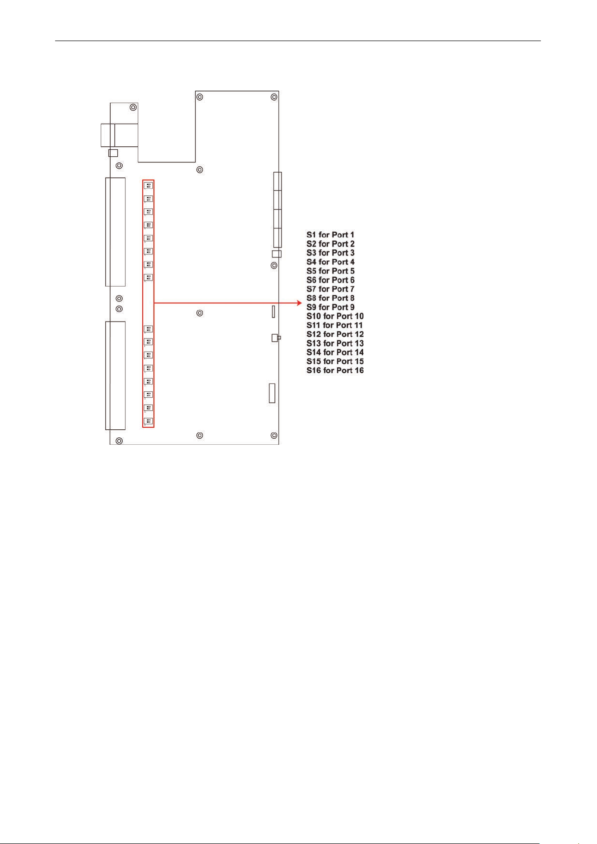
Adjustable Pull High/low Resistors for the RS-485 Port
In some critical environments, yo u may need to add termination r e s is tor s to prevent the refle c tion of serial
signals. When using termination resistors, it is important to set the pull high/low resistors correctly so that the
electrical signal is not corrupted. Since a particular pull high/low resistor value cannot fit all environments, the
NPort 5650 uses DIP switches to set the pull high/low resistor values for each serial por t.
To set the pull high/low resistors to 150 KΩ, make sure both of the assigned DIP switches are in the OFF
position. This is the default setting.
To set the pull high/low resistors to 1 KΩ, make sure both of the assigned DIP switches are in the ON
position.
not use the 1 KΩ setting on the NPort 5650 when using the RS-232 interface. Do ing so will de gr ade the
-232 signals, shorten the maximum allowed communication dis ta nc e , and the Rx LED may light up.
Page 15
NPort 5600 Series Getting Started
2-6
NPort 5650 DIP Switches
Page 16

3
3. Initial IP Address Configuration
When setting up your NPort 5600 for the first time, the first thing you should do is configure the IP address. This
chapter introduces several methods to conf igur e NPor t’ s IP address . Select the metho d that is the mos t
convenient for you. For more details about network settings, see the Network Settings section from Chapter 5,
Web Console Configuration.
The following topics are covered in this chapter:
Initializing NPor t’ s IP A ddress
Factory Default IP Address
LCM Display
NPort Administration Suite
ARP
Telnet Console
Page 17

NPort 5600 Series Initial IP Addre ss Configuration
3-2
ATTENTION
Consult your network administrato r o n how to reserv e a fixed I P address (for yo ur NPor t
mapping table when using a DHCP Server or BOOTP Server. In most applications, you should assign a fixed IP
address to your NPort.
N P 5 6 1 0 - 1 6 _ 3 8
1 9 2 . 1 6 8 . 1 2 7 . 2 5 4
•
is the
•
is the NPort’s serial number
•
is the NPort’s IP address
Initializing NPort’s IP Address
1. Determine whether your NPort needs to use a Static IP or Dynamic IP (either DHCP or BOOTP application).
2. If NPort is used in a Static I P environment, you can use NPort Administration Suite, ARP, Web Console,
or Telnet Console to configure the new IP addre ss.
3. If NPort is used in a Dy na m ic IP e nv ir o nment, you can use NPort Administration suite, Web Console,
or Telnet Console to configure NPort to get an IP address dynamically with DHCP, DHCP/BOOTP, or BOOTP.
Factory Default IP Address
NPort products are configured with the following default private IP address:
Default IP address: 192.168.127.254
(IP addresses of the form 192.168.xxx.xxx are referr ed to as priv ate IP addre s s es, si nc e it is not possib le to
directly access a device configured with a private IP address from a public network. For example, you would not
be able to ping such a device from an outside Internet connection. NPort applications that require sending data
over a public network, such as the Internet, require setting up the server with a valid public IP address, which
can be leased from a local ISP.)
LCM Display
We recommend using the LCM display and four push buttons to co nfig ure the IP addre s s for the first time.
Basic Operation
If the NPort is working properly, the LCM panel will display a green color. The red Ready LED will also light up,
indicating that the NPort is receiving power. After the red Ready LED turns green, you will see a display similar
to:
) in the MAC-IP
Where
NP5610-16
38
192.168.127.254
There are four push buttons on NPort’s nameplate. Going from left to right, the b utto ns are:
Button Name Action
menu menu activates the main menu, or returns to an upper level
sel select selects the option listed on the LCM panel’s second line
The buttons are manipulated in a manner similar to the way a modern cellular p hone operate s . A s you move
through the various functions and setting options, note that the top line shows the current menu or submenu
name, and the bottom line shows the submenu name or menu item that is activated by pressing the SEL
button.
up cursor scrolls up through a list of items shown on the LCM panel’s second line
down cursor scrolls down through a list of items shown on the LCM panel’s second line
NPort’s name
Page 18

NPort 5600 Series Initial IP Addre ss Configuration
3-3
N P 5 6 1 0 - 1 6 _ 3 8
1 9 2 . 1 6 8 . 1 2 7 . 2 5 4
M a i n M e n U
S e r v e r s e t t i n g
Detailed Menu Options
The best way to explain all of NPort’s LCM functions is to refer to the table shown on the next page. There are
three main levels—1, 2, and 3—with eac h lev e l repres e nte d by a separate column.
The first thing to remember is that the MENU button is used to move back and forth between the LCM panel’s
default screen, and main menu screen:
↓
In addition, you only need to remember to:
• Use the SEL button to move up one level (i.e., left to right on the tree graph)
• Use the MENU button to move down one level (i.e., right to left on the tree grap h)
• Use the cursor keys, and , to scroll between the various options within a level (i.e., up and down on the
tree graph).
As you use the buttons to operate the LCM display, you will notice that with very few exceptions, moving up one
level causes the bottom line of the display to move to the top line of the display. You will also notice that the
bottom three options in level 2, and all of the options in level 3 have either a C or D attached. The meaning is
as follows:
• C = configurable (i.e., you are allowed to change the setting of this opti o n)
• D = display only (i.e., the setting for this option is displayed, but it cannot be changed)
This does NOT necessarily mean that the number does not change; o nly that you canno t change it.
Page 19

NPort 5600 Series Initial IP Addre ss Configuration
3-4
Level 1 Level 2 Level 3
Main Menu
Server setting Serial number
Server n a me
Firmware ver
Model name
Network
setting
Serial set Select port
Op Mode set Select port
Console Web console
Ping C
Save/Restart C
Ethernet status
MAC address
IP config
IP address
Netmask
Gateway
DNS server 1
DNS server 2
Baudrate
Data bit
Stop bit
Parity
Flow control
Tx/Rx fifo
Interface
Tx/Rx bytes
Line status
Select mode
[mode]
Real COM
Alive timeout
Max connection
Delimiter 1
Delimiter 2
Force Tx
Telnet console
TCP server
Alive timeout
Inact. time
Max connection
Delimiter 1
Delimiter 2
Force Tx
Local TCP port
Command port
TCP client
Alive timeout
Inact. time
Delimiter 1
Delimiter 2
Force Tx
Dest IP-1
TCP port-1
Dest IP-2
TCP port-2
Dest IP-3
TCP port-3
Dest IP-4
TCP port-4
TCP connect
UDP svr/cli
Delimiter 1
Delimiter 2
Force Tx
Dest IP start-1
Dest IP end-1
Dest port-1
Dest IP start-2
Dest IP end-2
Dest port-2
Dest IP start-3
Dest IP end-3
Dest port-3
Dest IP start-4
Dest IP end-4
Dest port-4
Local port
D
C
D
D
D
D
C
C
C
C
C
C
C
C
C
C
C
C
C
C
D
D
C
C
C
C
C
C
C
C
C
C
C
C
C
C
C
C
C
C
C
C
The part of the LCM operation that still requires so me explanatio n is ho w to edit the configurable options. In
fact, you will only encounter two types of config urab le options.
Page 20

NPort 5600 Series Initial IP Addre ss Configuration
3-5
P a r I t Y
N O n E
P a r I t Y
O D D
P a r i T Y
E v e n
P a r i T Y
S p a c E
P a r i t Y
M a r k
NOTE
Wide temp. model
ATTENTION
In order to use this setu
Or, you may
Your
ARP command, as described below.
The first type involves entering numbers , such as IP addresse s , Netmas ks, etc. In this case, you change the
number one digit at a time. The up cursor () is used to decrease the highlighted digit, the down cursor ()
is used to increase the highlighted digit, and the sel button is used to move to the next digit. When the last digit
has been changed, pressing sel simply enters the number into NPor t 5600 Series’ memory.
The second type of configurable option is when there are only a small number of options from which to choose
(although only one option will be visible at a time). Consider the Parity attribute under Serial s et as an example.
Follow the tree graph to arrive at the following Parity screen. The first option, None, is displayed, with a down
arrow all the way to the right. This is an indicati o n that the re are othe r options from which to choose.
↓
Press the down cursor button once to see Odd as the second option.
↓
Press the down cursor button again to see Even as the third option.
↓
Press the down cursor button again to see Space as the fourth option.
Press the down cursor button yet again to see the last option, Mark.
To choose the desired option, press the SEL button when the option is showing on the screen.
does not support LCM Panel and Push Buttons.
NPort Administration Suite
NPort Administration Suite consists of some useful utility programs that are used to configure and manage your
NPorts.
See Chapter 6 for details on how to i nstal l NP ort Administra tion Suite , a nd how to use this s uite of
useful utilities to se t up IP addr e s se s and conf i gur e your NPo rt.
ARP
You can make use of the ARP (Address Resolution Protocol) command to set up an IP address for your NPort.
The ARP command tells your computer to associate the NPort’s MAC address with t he inten ded IP ad dress. You
must then use Telnet to access the NPort, at which point the Device Server’s IP address will be reconfigure d .
↓
↓
NPort must be configured with the factory default IP address—192.168.127.254—before executing the
Take the following steps to use ARP to configure the IP address:
p method, both your computer and NPort must be connected to the same LAN.
use a cross-over Ethernet cable to connect the NPort directly to your comp uter’ s Ethernet card.
Page 21
NPort 5600 Series Initial IP Addre ss Configuration
3-6
ATTENTION
Figures in this section will
1. Obtain a valid IP address for your NPort from your network administrator.
2. Obtain the NPort’s MA C address fro m the lab e l on its bottom pane l.
3. Execute the ‘arp -s’ command from your computer’s MS-DOS prompt by typing :
arp –s 192.168.200.100 00-90-E8-xx-xx-xx
This is where 192.168.200.100 is the new IP address and 00-90-E8-xx-xx-xx is the MAC address for your NPort.
You will need to change both numbers, as described above in points 1 and 2.
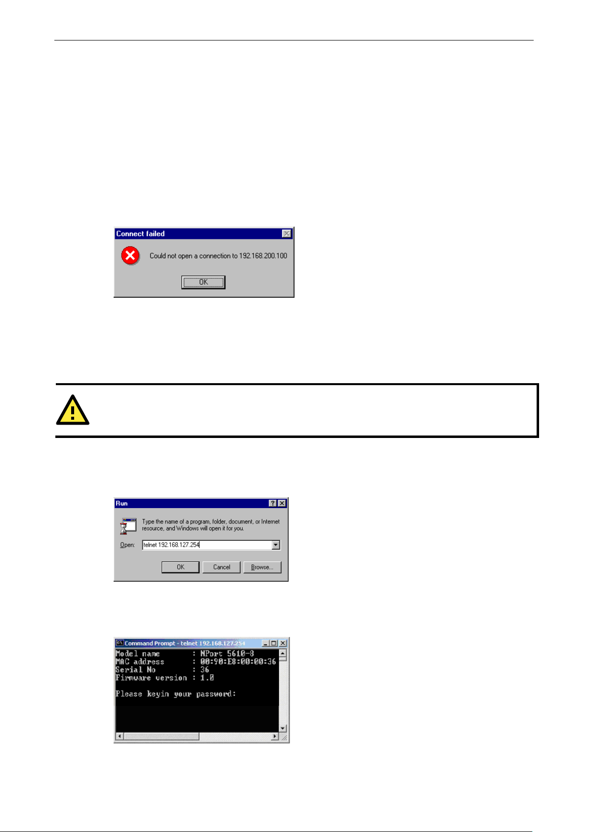
4. Next, execute a special Telne t c omma nd by typing :
telnet 192.168.200.100 6000
After issuing this command, a Connect failed message will appear, as shown here. After the NPort reboots,
its IP address should be updated to the new address, and you can reconnect us ing Te lne t, Web , or
Administrator to check that the update was succe ssf ul.
Telnet Console
Depending on how your computer and network are configured, you may find it convenient to use network
access to set up your NPort’s IP address. This can be done using the Telnet program .
1. From the Windows desktop , click Start and then select Run.
2. Type telnet 192.168.127.254 (use the correct IP address if different from the default) in the Open text
input box, and then click OK.
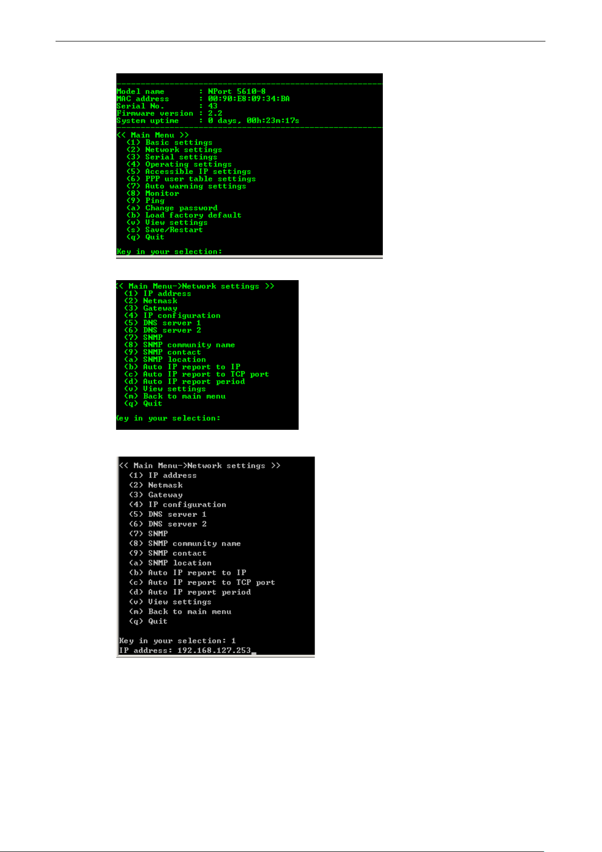
3. When the Telnet window opens, if you are prompted to input the Console password, input the password and
then press Enter.
Note that this page will only appear if the NPort is password pro te c ted .
use 5610-8 as an example.
Page 22
NPort 5600 Series Initial IP Addre ss Configuration
3-7
4. Type 2 to select Network setting s , a nd then pr e ss Enter.
5. Typ e 1 to select IP address and then press Enter.
6. Use the Backspace key to e rase the current IP address, type in the n ew IP address, and th en press Enter.
Page 23
NPort 5600 Series Initial IP Addre ss Configuration
3-8
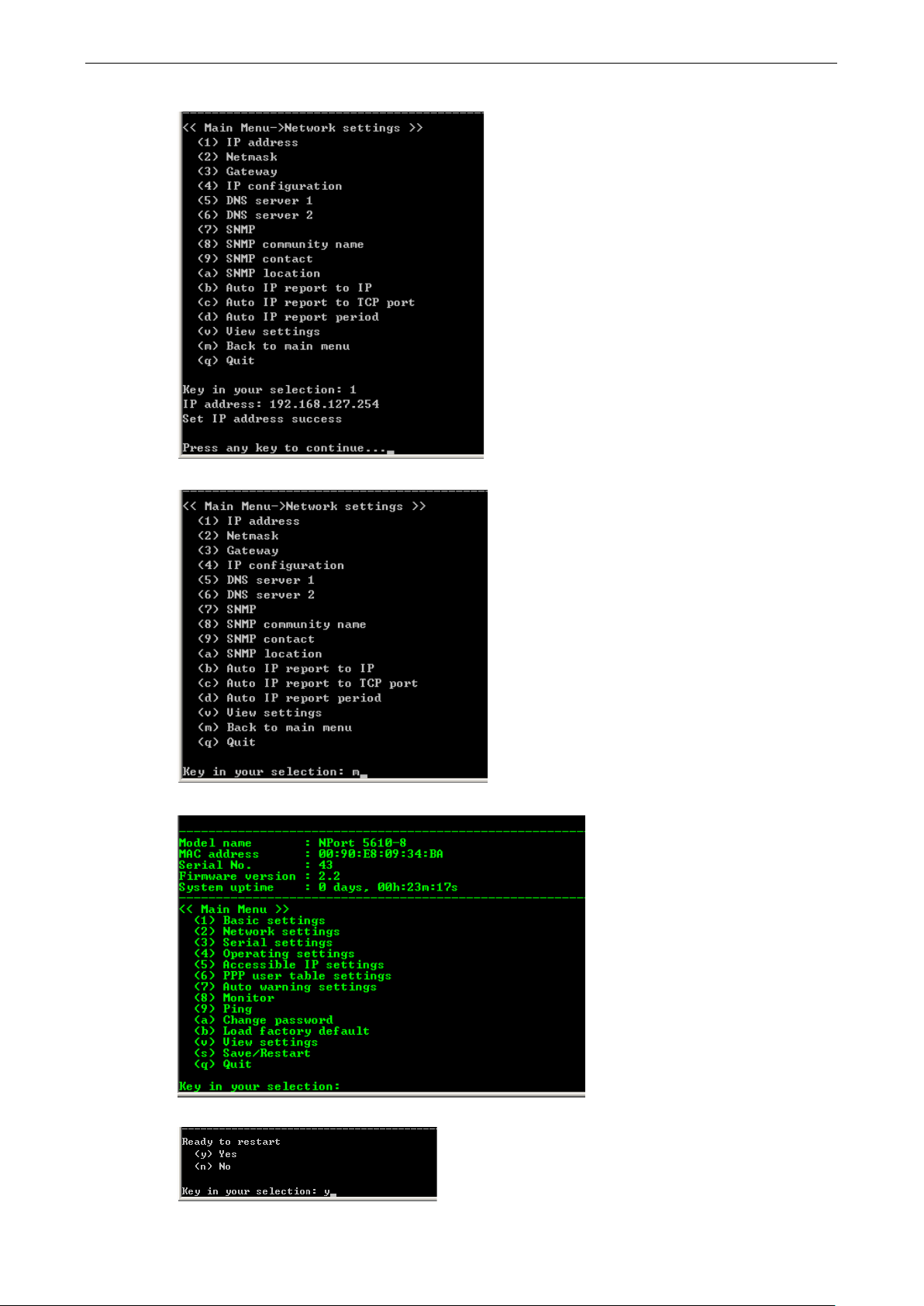
7. Press any key to continue…
8. Typ e m or M and then press Enter to return to the main menu.
9. Typ e s or S and then press Enter to Save/Restart the system.
10. Typ e y or Y and then press Enter to save the new IP address and restart NPort.
Page 24

4
4. Choosing the Proper Operation Mode
In this chapter, we describe the various NPort 5600 operation modes. The options include an operation mode
that uses a driver installed on the host computer, and operation modes that rely on TCP/IP socket programming
concepts. After choosing the proper operation mode in this chapter, refer to Chapter 5 for detailed
configuration parameter definitions.
The following topics are covered in this chapter:
Overview
Real COM Mode
TCP Server Mode
TCP Client Mode
UDP Mode
Pair Connection Mode
Reverse Telnet Mode
Disabled Mode
RFC2217 Mode
PPP Mode
Page 25
NPort 5600 Series Choosing the Proper Operation Mo de
4-2
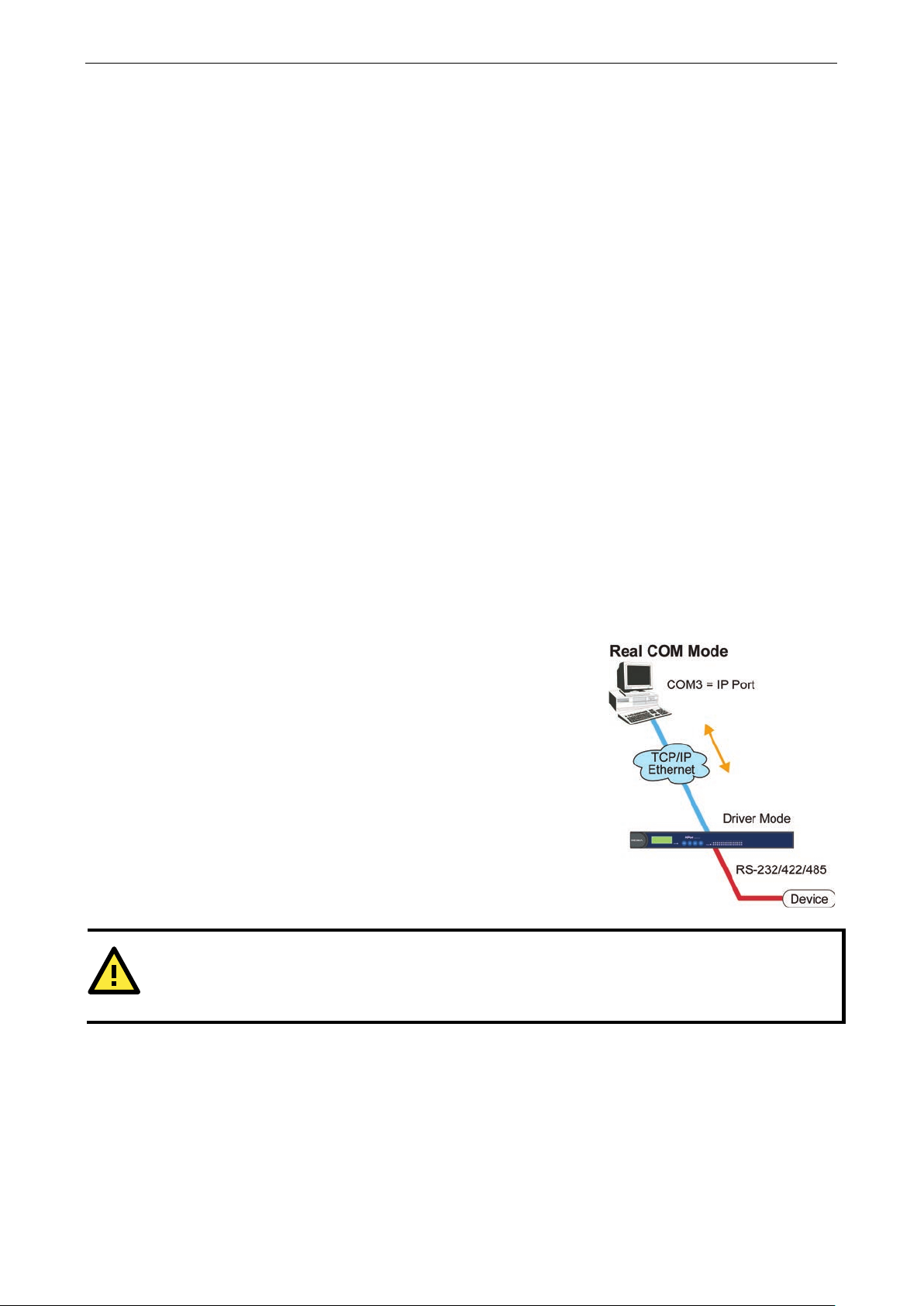
NPort comes equipped with COM drivers that work with Windows
95/98/ME/N T / 2000/XP/2003/Vista/2008/7/8, Windows 2012
systems, and also TTY drivers for Linux systems. The driver
establishes a transparent connectio n b e twee n host a nd serial
device by mapping the IP:Port of the NPort’s serial port to a local
COM/TTY port on the host computer.
supports up to 4 simultaneous connections, so that multiple hosts
can collect data from the same serial device at the same time.
ATTENTION
The driver used for Real COM Mode comes with the NPort Windows Administr ator. The driver is installed
automatically on your computer when you install NPo rt Administration Suite.
Overview
NPort Device Servers network-enable traditional RS-232/422/485 devices, in w hi c h a Device Serv e r is a tiny
computer equipped with a CPU, real-time OS, and TCP/IP protocols that can bi-directionally translate data
between the serial and Ethernet formats . Your computer can access, manage, and configure remote facilities
and equipment over the Internet from anywhere in the world.
Traditional SCADA and data collection sy s te ms rely on serial p rots (RS-232/422/485) to collect data from
various kinds of instruments. Since NPort Serial Device Servers network-enable instruments equipped with an
RS-232/422/485 communication port, your SCADA and data co lle c tion system will be able to access all
instruments connected to a standard TCP/IP network, regardless of whether the devices are used l ocally or at
a remote site.
NPort is an external IP-based network device that allow s you to expand the number of ser ial p orts for a host
computer on demand. As long as your host computer supports the TCP/IP protocol, you won’t be limited by the
host computer’s bus limitation (suc h as ISA or PCI), or lack of driv ers for v arious operating systems.
In addition to providing socket access, NPort al so com es with a Real COM/TT Y dr iver that transmits all serial
signals intact. This means that your existing COM/TTY-based software can be preserved , without nee d ing to
invest in additional software.
Three different Socket Modes are available: TCP Server , TCP Client, and UDP Server/Client. The main
difference between the TCP and UDP protocols is that TCP guarantees delivery of data by requiring the recipient
to send an acknowledgement to the sender. UDP does not require this type of verification, making it possible
to offer speedier delivery. UDP also allows multicas ting of data to groups of IP addresses.
Real COM Mode
This operation mode also
The important point is that Real COM Mode allows users to continue us ing RS -232/422/485 serial
communications software that was writte n fo r pure serial c ommunic ati o ns applications. The driver intercepts
data sent to the host’s COM port, packs it into a TCP/IP packet, and then redirects it through the host’s Ethernet
card. At the other end of the connection, the NPort accepts the Ethernet frame, unpacks the TCP/IP packet, and
then transparently sends it to the appropriate seri al d ev ic e attached to o ne of the NPort’ s serial ports.
Page 26

NPort 5600 Series Choosing the Proper Operation Mo de
4-3
ATTENTION
Real COM
with
your NPort controls host access to attached ser ia l devic e s by checking
Modify the
In TCP Server mode, NPort provides a unique IP:Port address on a
TCP/IP network. NPort waits passively to be contacted by the host
computer, allowin
with and get data from the serial device. This operation mode also
supports up to 4 simultaneous connections, so that multiple hosts
can collect data from the same serial device
As illustrated
The host requests a connection from the NPort configured for TCP
Server Mode.
Once the connection is established, data can be trans mitte d in
both directions
rt to
the host.
In TCP Client mode, NPort can actively establish a TCP connection
to a pre
After the data has been transferred, NPort can autom atic al ly
disconnect from the host computer by using the TCP alive check
time or Inactivity time settings. Refer to chapter 5 for more
details.
As illustrated in the figure, data transmission proceeds as follows:
The NPort configured for TCP Client Mode requests a connectio n
from the host.
Once the
both directions—from the host to the NPort, and from the NPort to
the host.
Mode allows several hosts to have access control over the same NPort. The driver that comes
Accessible IP Setting table when the legal IP address should be requir ed in your applica tio n.
TCP Server Mode
g the host computer to establish a connection
in the figure, data transmission proceeds as follows:
—from the host to the NPort, and from the NPo
the host’s IP address.
—at the same time.
TCP Client Mode
-defined host computer when serial data arrives.
connection is established, data can be transmitte d in
Page 27

NPort 5600 Series Choosing the Proper Operation Mo de
4-4
Compared to TCP communication, UDP is faster and more
efficient. In UDP mode, you can multicast data from the ser
device to multiple host computers, and the ser ial devic e can also
receive data from multiple host computers, making this mode
ideal for message display applications .
Console
connecting to
routers, switches, an
works the same as RAW mode
one
TCP port is
system then
host on the network to
ini
connection. The difference is that the
RAW mode does not provide
function
elnet. If the connected
devices need to use
function when controlling, then users
choose
UDP Mode
ial
Pair Connection Mode
Pair Connection Mode employs two NPort 5600 in tandem, and can be used to remove the 15-meter distance
limitation imposed by the RS-232 interface. One NPort 5600 is connected from its RS-232 port to the COM port
of a PC or other type of computer, such as hand-held PDAs that have a serial port, and the serial de v ic e is
connected to the RS-232 port of the other NPort 5600. The two NPort 5600 units are then co nne c te d to each
other with a cross-over Ethernet cable, both are connected to the same LAN, or in a more advanced setup, they
communicate with each othe r over a WAN (i.e., through one or more routers). Pair Connection Mode
transparently transfers both data and modem control signals (although it cannot transmit the DCD signal)
between the two NPorts.
Reverse Telnet Mo d e
management is commonly used by
Console/AUX or COM ports of
d UPS units. Rtelnet
in that only
listened to after booting up. The
waits for a
tiate a
the conversion
provided by T
Rtelnet mode.
the CR/LF conversion
must
Page 28
NPort 5600 Series Choosing the Proper Operation Mo de
4-5
Disabled Mode
Setting the operation mode of a particular port to Disabled, disables that port.
RFC2217 Mode
RFC2217 is a standard driver that provides Virtual COM function. RFC2217 defines general com port control
options based on telnet protocol. Any 3rd party driv er suppor ting RFC 22 17 ca n be used to implement virtual
COM on NPort 5600 series. The driver establishes a transparent connection between host and serial device by
mapping the IP:Port of the NPort 5600 series’ serial port to a local COM port on the host computer. (RFC2217
Mode supports 1 connection)
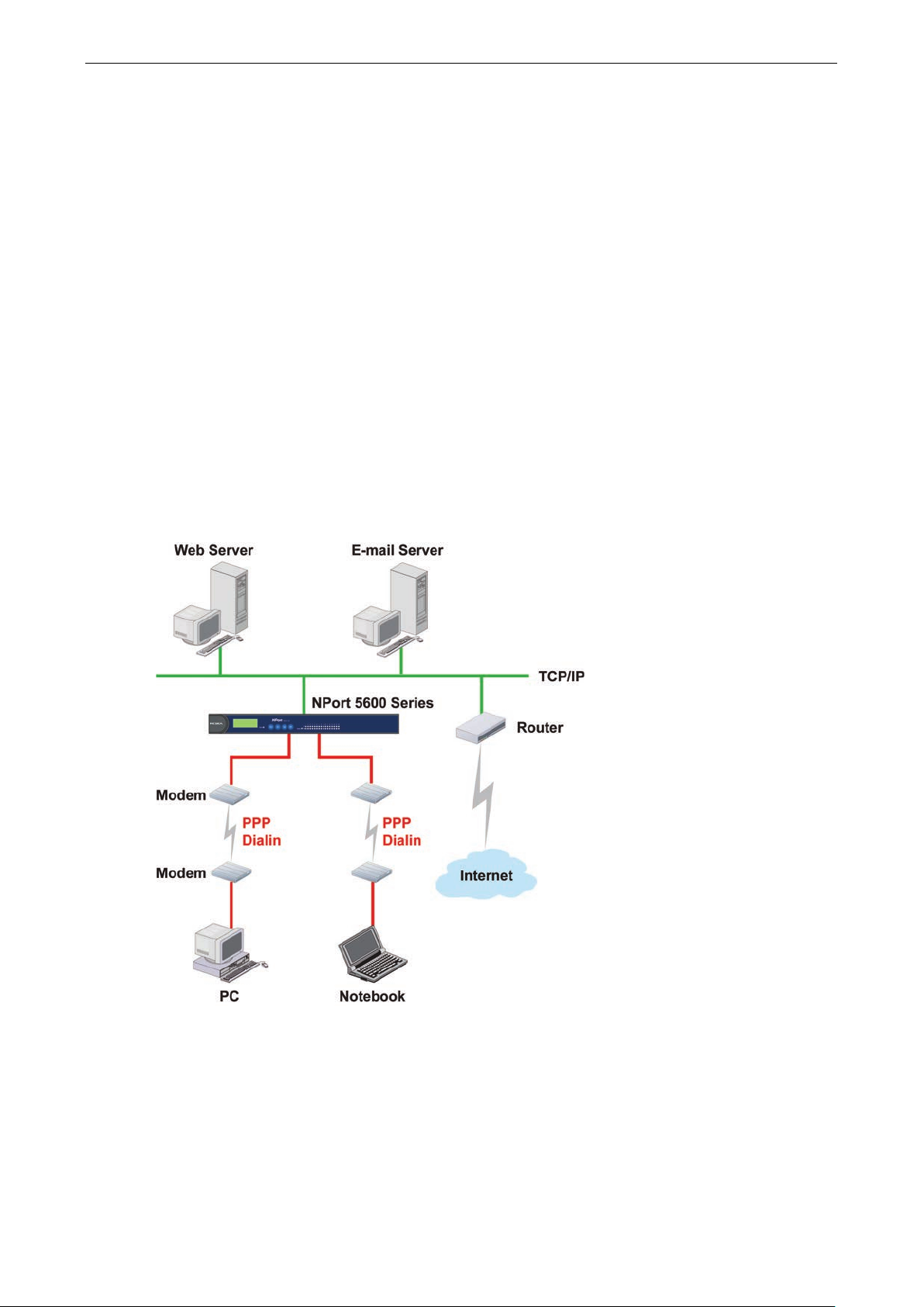
PPP Mode
NPort 5600 Device Server supports standard PPP service for out-of-band management if the Ethernet network
crashes. The PPP function enables dial-in access for users who need a remote access solution. When a user at
a remote site uses PPP dial-in to connect to NPort 5600, NPort 5600 plays the role of a dial-in server. After the
PPP connection is established, the us er can remote ly m anage the NPor t 5600.
Please refer to Chapter 5 for detailed inform ation and configuration instructions.
Page 29

5
5. Web Console Configuration
The Web Console is the most user-friendly method availab le to c o nfig ure NPor t 5600 Serie s .
The following topics are covered in this chapte r:
Opening Your Browser
Basic Settings
Time
Console
Network Settings
S NMP S e ttings
IP Address Report
Serial Settings
S e rial Parameters
Operating Settings
Real COM Mode
TCP Server Mode
TC P C li e nt Mode
UDP Mode
Pair Connection Mode
Pair Connection Master Mode
Pair Connection Slave Mode
Reverse Telnet Mode
D is a b le d Mode
RFC2217 Mode
PPP Mo d e
Accessible IP Settings
PPP User Table
Auto Warning Setti ng s
A uto warning: E-mail and SNMP Trap
Ev e nt Typ e
Monitor
Mo nitor Line
Monitor Async
Monitor Async-Settings
Change Password
Load Factory Defaults
Page 30
NPort 5600 Series Web Console Confi guration
5-2
ATTENTION
If you use other web browsers, remember to Enable the functions to
computer
NPort 5600 series uses cookies only for
Opening Your Browser
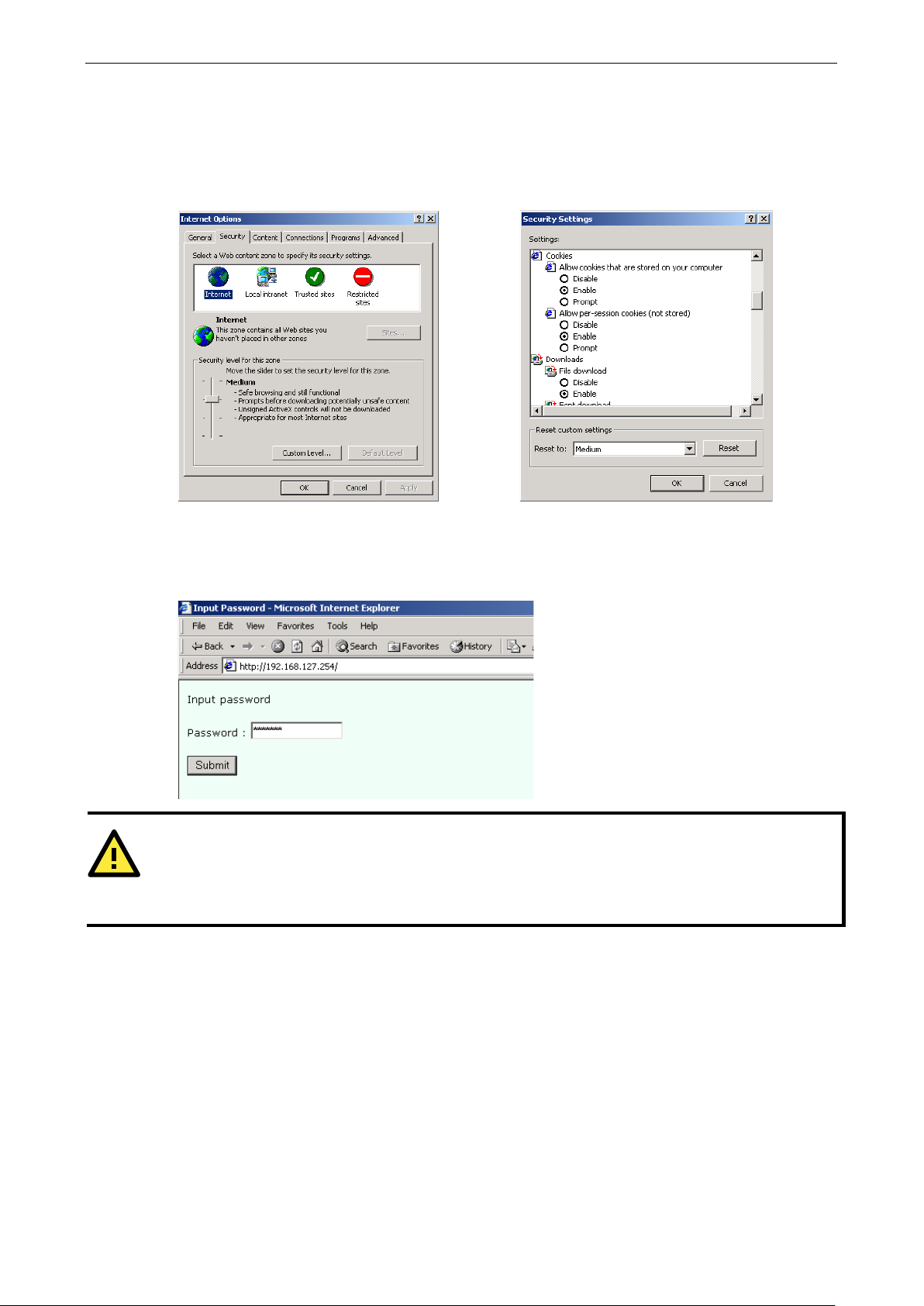
1. Open your browser with the cookie function enabled. (To enable your browser for cookies, right click your
desktop Internet Explorer icon, selec t Prop ertie s , c li c k the Securi ty tab, and then s e lect the thre e Enab le
options as shown in the figure below.)
2. Type 192.168.127 .25 4 in the Ad dr e ss inp ut box (use the corr ect I P addre s s if diff er e nt from the default),
and then press Enter.
3. Input the password if prompted. The password will be transmitted with MD5 encryption over the Ethernet.
Note that you will not be prompted to enter the password if the NPort is not currently password protected.
” or “allow per-session cookies.”
“password” transmission.
“allow cookies that are stored on your
Page 31

NPort 5600 Series Web Console Confi guration
5-3
ATTENTION
If you can’t remember the password, the ONLY way to start configur ing NPor t
using the Reset button
Remember to
configuration. After using the Reset button to load factory defaults, your configuration can be easily reloaded
into NPort by using the
for more details about using
the Export and Import functions.
ATTENTION
If your NPort
browser. If the cookie function is disabled , you will no t be allowe d to enter the W eb Console Scree n.
4. The NPort 5600 homepage will open. On this page, you can see a brief description of the Web Console’s nine
function groups.
use NPort Administrator to export the conf igur ation file when you have finished the
application requires using password pro tection, you must enable the cookie function in your
located near the NPort’s RJ45 Ethernet por t.
NPort Administrator Import function. Refer to Chapte r 6
Basic Settings
is to load factory defaults by
Server name
Setting Factory Defa ult Necessity
1 to 39 characters NP[model name]-[Port No.]_ [Serial No.] Optional
This option is useful for specifying the location or application of different NPorts.
Page 32

NPort 5600 Series Web Console Confi guration
5-4
ATTENTION
First time users should select the time zone first. The Console will display the “real time” according to the time
zone compared to GMT.
If you would like to modify the real time clock, select “Local time.” NPort’s firmware will modify the GMT time
according to the Time Zone.
Time
NPort 5600 has a built-in Real-Time Clock for time calibration functions. Functions such as Auto warning “Email”
or “SNMP Trap” can add real-time information to the message.
Time zone
Setting Factory Default Necessity
User selectable time
zone
Local time
Setting Factory Defa ult Necessity
User adjustable time.
(1900/1/1-2037/12/31
)
Click the Modify button to open the Modify time settings window to input the correc t loc al tim e .
GMT (Greenwich Mean Time) Optional
GMT (Greenwich Mean Time) Optional
Time server
Setting Factory Defa ult Necessity
IP or Domain address
(E.g., 192.168.1.1 or
time.stdtime.gov.tw)
NPort 5600 uses SNTP (RFC-2030) for auto time calibration.
Input the correct “Time server” IP address or domain address. Once NPort is configured with the correct Time
Server address, NPort will request time information from the “Time server” every 10 minutes.
Console
The “Disable” option for Web Console and Telnet Console is included for security reasons. In some cases, you
may want to Disable one or both of these Console utilities as an extra precaution to prevent unauthorized users
from accessing your NPort. The factory default for both Web Console and Telnet Console is Enable.
Setting Factory Defa ult Necessity
Enable or Disable Enable Required
None Optional
Page 33

NPort 5600 Series Web Console Confi guration
5-5
ATTENTION
If you disable both the “Web Console” and “Telnet Console ,” yo u can still us e the
NPort locally, or Windows Administrato r to configure NPort either locally or remotely over the network.
Network Settings
LCM Display to configure
You must assign a valid IP address to NPort 5600 before it will work in your network environment. Your network
system administrator should provide you with an IP address and related settings for your network. The IP
address must be unique within the network (other w ise, N Port 5600 will not have a valid connection to the
network). First time users can refer to Chapter 3, Initial IP Address Configuration, for more information.
You can choose from four possible IP Configuration modes—Static, DHCP, DHCP/BOOTP, and BOOTP—
located under the web console screen’s IP configuration drop-down box.
Method Function Definition
Static User defined IP addre ss, Netmask, Gateway.
DHCP DHCP Server assigned IP address, Netmask, Gateway, DNS, and Time Server
DHCP/BOOTP DHCP Server assigned IP address, Netmask, Gateway, DNS, and Time Server, or BOOTP
Server assigned IP address (if the DHCP Server does not respond)
BOOTP BOOTP Server assigned IP addres s
IP Address
Setting Factory Defa ult Necessity
E.g., 192.168.1.1 (IP
addresses of the form
x.x.x.0 and x.x.x.255
are invalid.)
An IP address is a number assigned to a network device (su ch a s a computer) as a permanent a ddress on t he
network. Computers use the IP address to identify and talk to each other over the network. Choose a proper IP
address which is unique and valid in your network environment.
192.168.127.254 Required
Page 34

NPort 5600 Series Web Console Confi guration
5-6
BOOTP
ATTENTION
In Dynamic IP environments,
assigned by the DHCP or BOOTP server. The Timeout for each try increases f rom 1 se con d, to 3 sec onds, t o 5
seconds.
If the DHCP/BOOTP Server is un
N
Netmask
Setting Factory Defa ult Necessity
E.g., 255.255.255.0 255.255.255.0 Required
A subnet mask represents all the network hosts at one geographic location, in one building, or on the same local
area network. When a packet is sent out over the network, the NPort will use the subnet mask to check if the
desired TCP/IP host specified in the packet is on the local network segment. If the addre s s is on the same
network segment as the NPort, a connection is established directly from the NPort. Otherwise, the connection
is established through the given default gate way.
Gateway
Setting Factory Default Necessity
E.g., 192.168.1.1 None Optional
A gateway is a network gateway that acts as an entrance to another netwo rk . U s ually, the computers that
control traffic within the network or at the local Inter net servic e provid er are gate way nodes. NPort needs to
know the IP address of the default gateway computer in order to communicate with the hosts outside the local
network environment. For correct gateway IP address information, consult the network administrator.
IP Configuration
Setting Factory Default Necessity
Static
DHCP
DHCP/BOOTP
Static Required
etmask, and Gateway for IP settings.
DNS server 1 / DNS server 2
Setting Factory Defa ult Necessity
E.g., 192.168.1.1
(IP addresses of the
form x.x.x.0 and
x.x.x.255 are invalid.)
When the user wants to visit a particular website, the computer asks a Domain Name System (DNS) server for
the website’s correct IP address, and the computer users the response to connect to the web server . DNS is the
way that Internet domain names are identified and translated into IP address es. A domain name is an
alphanumeric name, such as moxa.com, that it is usually easier to remember. A DNS server is a host that
translates this kind of text-based domain name into the numeric IP address used to establish a TCP/IP
connection.
the firmware will retry 3 times every 30 seconds until network se ttings are
available, the firmware will use the default IP address (192.168.127.254),
None Optional
In order to use NPort’s DNS feature, you need to set the IP a ddress of th e DNS serv er to be able to ac cess the
host with the domain name. NPort provides DNS server 1 and DNS server 2 configuration items to configure
the IP address of the DNS server. DNS Server 2 is included for use when DNS sever 1 is unavailable.
NPort plays the role of DNS client. Functions that support domain name in NPort are Time Sever IP Address,
TCP Client-Destination IP Address, Mail Server, SNMP Trap IP Address, and IP Location Server.
Page 35

NPort 5600 Series Web Console Confi guration
5-7
SNMP Settings
Community name
Setting Factory Defa ult Necessity
1 to 39 characters
(E.g., Support,
886-89191230 #300)
A community name is a plain-text password mechanism that is used to weakly authenticate queries to agents
of managed network d evices.
Contact
Setting Factory Defa ult Necessity
1 to 39 characters
(E.g., Support,
886-89191230 #300)
The SNMP contact information usually inc ludes an emergency contact name and telephone or pager number.
Location
Setting Factory Defa ult Necessity
1 to 39 characters
(E.g., Floor 1, office 2)
public Optional
None Optional
None Optional
Specify the location string for SNMP agents such as NP ort. This string is usually set to the street address where
the NPort is physically located.
IP Address Report
When NPort 5600 series products are used in a dynamic IP environment, users must spend more time with IP
management tasks. For example, if NPort works as a server (TCP or UDP), then the host, which acts as a client,
must know the IP address of the server. If the DHCP server assigns a n ew IP address to NPort, the host must
have some way of determining NPort’s new IP address. NPort 5000 series products help out by periodically
reporting their IP address to the IP location server, in case the dynamic IP has changed. The parameters shown
below are used to configure the Auto IP report function. Ther e are two way s to develop an “Auto IP repo r t
Server” to receive NPort’s Auto IP report.
1. Use NPort Administrator’s IP Address Report function.
2. “Auto IP report protoc ol ,” which can automatically receive the Auto IP repor t on a regular b as is , is also
available to help you develop your own soft w a re. Refer to Appendix E for the “Auto IP report protocol”.
Auto report to IP
Setting Factory Defa ult Necessity
E.g., 192.168.1.1
(IP addresses of the
form x.x.x.0 and
x.x.x.255 are invalid.)
None Optional
Reports generated by the Auto report function will be sent automatically to this IP address.
Auto report to UDP port
Setting Factory Defa ult Necessity
E.g., 4001 None Optional
Auto report period
Setting Factory Defa ult Necessity
Time interval (in
seconds)
10 Optional
Page 36

NPort 5600 Series Web Console Confi guration
5-8
Serial Settings
Click Serial Settings, loc ate d unde r Main Menu, to display serial port settings for ports 1 and 2.
NOTE: Once you have completed the hardware installation of NPort 5600, there should be either 16 or 8 ports
shown in the figure, depending on the model you installed . The ste ps for chang ing the se ttings of the other
ports are the same as those for Port 1 and Port 2.
To modify serial settings for a particular port, click either Port 1 or Port 2 under Serial Settings, located
under Main Menu on the left side of the browser window
Port alias
Setting Factory Defa ult Necessity
1 to 15 characters
(E.g., PLC-No.1)
None Optional
“Port Alias” is specially designed to allow easy identification of the serial devices which are connected to NPort’s
serial port.
Page 37

NPort 5600 Series Web Console Confi guration
5-9
ATTENTION
Check the serial communication parame ter s in your Ser ial De v ice
ou should set up NPort’s
serial parameters with
Serial Parameters
Baudrate
Setting Factory Defa ult Necessity
50 bps to921.6 Kbps 115.2 Kbps Required
Data bits
Setting Factory Defa ult Necessity
5, 6, 7, 8 8 Required
When the user sets Data bits to 5 bits, the stop bits setting will automatically change to 1.5 bits.
Stop bits
Setting Factory Defa ult Necessity
1, 1.5, 2 1 Required
Stop bits will be set to 1.5 when Data bits is set to 5 bits.
Parity
Setting Factory Defa ult Necessity
None, Even, Odd,
Space, Mark
Flow control
Setting Factory Defa ult Necessity
None, RTS/CTS,
DTR/DSR, Xon/Xoff
the same communication parameters used by your serial devices.
None Required
RTS/CTS Required
’s user’s manual. Y
FIFO
Setting Factory Defa ult Necessity
Enable, Disable Enable Required
NPort’s serial ports provide a 16-byte FIFO both in the Tx and Rx directions. Disable the FIFO setting when your
serial device does not have a FIFO to prevent data loss during communication.
Interface
Setting Factory Defa ult Necessity
NPort 5610-/16:
RS-232 only
NPort 5630-8/16:
RS-422/485 only
NPort 5650-8/16 RS-232 Required
RS-232 only Required
4-wire RS-485 Required
Page 38

NPort 5600 Series Web Console Confi guration
5-10
Operating Settings
Click Operating Setting s located under Main Menu, to display the operating settings for all of NPort’s serial
ports.
Real COM Mode
TCP alive check time
Setting Factory Defa ult Necessity
0 to 99 min 7 min Optional
0 min: TCP connection is not closed due to an idle TCP connection.
1 to 99 min: NPort automatically closes TCP connection if there is no TCP activity for the given time. After the
connection is closed, NPort starts listening for another Real COM driver connection from another host.
Max connection
Setting Factory Defa ult Necessity
1, 2, 3, 4 1 Required
Page 39

NPort 5600 Series Web Console Confi guration
5-11
ATTENTION
When Max connection is
will be using a “multi connection application”
(i.e., 2, 3, or 4 hosts are allowed access to the port at the same time). When using a multi connectio n
application, NPort will use the serial communication parameters set in
nected
to that port must use the same serial settings. If
port with parameters that are
different
Max connection is usually used when the user needs to receive data from different hosts simultaneously. The
factory default is 1. In this case, only one specific host can access this port of the NPort, and the Real COM
driver on that host will have full control over the port.
Max. connection 1:
Allows only a single host’s Real COM driver to open the specific NPort serial port.
Max connection 2 to 4:
Allows 2 to 4 hosts’ Real COM drivers to open the specific NPort serial port at the same time. When multiple
hosts’ Real COM drivers open the serial port at the same time, the COM driver only provides a pure data tunnel
without control ability. That is, this se rial port parameter will use firmware’s settings, not depend on your
application program (AP).
Application software that is based on the COM driver will receive a dri ver response of “success” when the
software uses any of the Win32 API functio ns. The fir mwar e will only send the data back to the driver on the
host.
Data will be sent first-in-first-out when data comes into the NPort from the Ethernet interface.
Ignore jammed IP
Setting Factory Defaul t Necessity
No or Yes No Required
For previous ver sions of NPort 5600, when Max connections > 1, and the serial device is transmitting data, if
any one of the connected hosts was not responding NPort 5600 would wait until the data had been transmitted
successfully before transmitting the second group of data to all hosts. For the current version of NPort 5600, if
you select Yes for “Ignore jammed IP,” the host that is not responding will be ignored, but the data will still be
transmitted to the other hosts.
Allow driver control
Setting Factory Defaul t Necessity
No or Yes No Required
If “max connection” is greater than 1, NPort will ignore drive r co ntro l com mands from all connec te d hosts .
However, if you set “Allow driver contro l” to YES, co ntro l command s will be accepted. Note that since NPort
5600 may get configuration changes from multiple hosts , the most rec e nt com ma nd receiv e d wil l tak e
precedence.
from NPort’s console setting, data communicatio n may not work pro perly.
Packing length
Setting Factory Defaul t Necessity
0 to 1024 0 Required
set to 2, 3, or 4, this means that NPort
the console. All of the hosts con
one of the hosts opens the COM
Default = 0, The Delimiter Process will be followed, regardless of the length of the data packet. If the data
length (in bytes) matches the configured value, the data will be forced out. The data length can be configured
for 0 to 1024 bytes. Set to 0 if you do not need to limit the length.
Delimiter 1
Setting Factory Defa ult Necessity
00 to FF None Optional
Page 40

NPort 5600 Series Web Console Confi guration
5-12
ATTENTION
Delimiter 2 is optional. If left blank, then Delimiter 1 alone
If the size of the serial
data received is greater than 1 KB, the NPort will automatica lly pack the data and send it to the Ethernet.
However, to use the delimiter function, you mus t at least enable De limi te r 1. If Delim ite r 1
Delimiter 2 is enabled, the delimiter func tion will not work properly.
Setting
Factory Defa ult
Necessity
Do nothing, Delimiter +
Delimiter 2
Setting Factory Defa ult Necessity
00 to FF None Optional
Once the NPort receives both delimiters thro ug h its ser ial po rt, it immediately packs all data currently in its
buffer and sends it to the NPort’s Etherne t port.
Delimiter process
Do Nothing Required
1, Delimiter + 2, Strip
Delimiter
When [Delimiter + 1] or [Delimiter + 2] is selected, the data will be transmitted when an additional byte (for
Delimiter +1), or an additional 2 bytes (for Delimiter +2 ) of data is rec e ived af ter receiving the Delimiter.
When [Strip Delimiter] is selected, when the Delimiter is received, the Delimiter is deleted (i.e., stripped), and
the remaining data is transmitted.
When [Do nothing] is selected, the data will be transmi tte d when the Delim ite r is re c e ived.
Force tran smit
Setting Factory Defa ult Necessity
0 to 65535 ms 0 ms Optional
0: Disable the force transmit timeout.
trips clearing of the buffer.
is left blank and
1 to 65535: Forces the NPort’s TCP/IP protocol software to try to pack serial data received during the specified
time into the same data frame.
This parameter defines the time interval during which NPort fetches the serial data from its internal buffer. If
data is incoming through the serial port, NPort s tor es the data in the internal buffer. NPort transmits data
stored in the buffer via TCP/IP, but only if the internal buffer is full or if the Force transmit time interval reaches
the time specified under Force transmit tim e o ut.
The optimal Force transmit timeout depend s on your app licatio n, but it must be at least larger than one
character interval within the specified baudrate. For example, assume that the serial port is set to 1200 bps, 8
data bits, 1 stop bit, and none for parity. In this case, the total number of bits needed to send a character is 10
bits, and the time required to transfer one character is
( 10 (bits) / 1200 (bits/s) ) * 1000 (ms/s) = 8.3 ms.
Therefore, you should set Force transmit timeout to be larger than 8.3 ms, so in this case, it must be greater
than or equal to 10 ms.
If the user wa nts to sen d the series of characte rs in the same packet, the serial device attached to NPort should
send that series of characters during a time interval le ss than the Forc e Tr ans m it timeo ut for N Por t, and the
total length of data must be less than or equal to NPort’s internal buffer size. The serial communication buffer
size for NPort is 1 KB per port.
Page 41

NPort 5600 Series Web Console Confi guration
5-13
ATTENTION
T
ransmit timeout. To prevent the unintended
loss of data due to the session
disconnected, it is highly recommended that this value is set large enough
so that the intended data trans
TCP Server Mode
TCP alive check time
Setting Factory Defa ult Necessity
0 to 99 min 7 min Optional
0 min: TCP connection is not closed due to an idle TCP connection.
1 to 99 min: NPort automatically closes the TCP connection if there is no TCP activity for the given time. After
the connection is closed, NPort starts listening for another host’s TCP connectio n.
Inactivity time
Setting Factory Defa ult Necessity
0 to 65535 ms 0 ms Optional
0 ms: TCP connection is not clos ed due to an idle serial line.
0-65535 ms: NPort automatically closes the TCP connection if there is no serial data activity for the given time.
After the connection is closed, NPort starts listening for another host’s TCP connectio n.
This parameter defines the maintenances status as Closed or Listen on the TCP connection. The connection is
closed if there is no incoming or outgoing data through the serial port d uring the specific Inactivity time.
If the Inactivity time is set to 0, the current TCP co nnectio n is k ept ac tive until a connection close request is
received. Although Inactivity time is disabled, the NPort will check the connection status between the NPort and
remote host by sending “keep ali ve” packets periodically. If the remote host does not respo nd to the packet,
NPort assumes that the connection was closed down unintentionally. NPort will then force the existing TC P
connection to close.
he Inactivity time should at least be set larger than that of Force t
Max connection
Setting Factory Defa ult Necessity
1, 2, 3, 4 1 Required
Max connection is usually used when the user needs to receive data from different hosts simultaneously. The
factory default only allows 1 connection at a time.
being
fer is completed.
Page 42

NPort 5600 Series Web Console Confi guration
5-14
Do nothing, Delimiter +
Max. connection 1:
NPort only allows 1 host to open the TC P connection to the specific serial port.
Max connection 2 to 4:
Allows 2 to 4 host’s TCP connection request to ope n this NPort serial port, at the same time. When multiple
hosts establish a TCP connection to the specific serial port at the same time, NPort will duplicate the serial data
and transmit to all of the hosts. Ethernet data is sent on a first-in-first-out basis to the serial port when data
comes into NPort from the Ethernet interface.
Ignore jammed IP
Setting Factory Defaul t Necessity
No or Yes No Required
For previous ver sions of NPort 5600, when Max connections > 1, and the serial device is transmitting data, if
any one of the connected hosts was not responding NPort 5600 would wait until the data had been transmitted
successfully before transmitting the second group of data to all hosts. For the current version of NPort 5600, if
you select Yes for “Ignore jammed IP,” the host that is not responding will be ignored, but the data will still be
transmitted to the other hosts.
Allow driver control
Setting Factory Defaul t Necessity
No or Yes No Required
If “max connection” is greater than 1, NPort will ignore drive r co ntro l com mands from all connec te d hosts .
However, if you set “Allow driver contro l” to YES, co ntro l command s will be accepted. Note that since NPort
5600 may get configuration changes from multiple hosts, the most recent command received will take
precedence.
Packing length
Setting Factory Defaul t Necessity
0 to 1024 0 Required
Default = 0, The Delimiter Process will be followed, regardless of the length of the data packet. If the data
length (in bytes) matches the configured value, the data will be forced out. The data length can be configured
for 0 to 1024 bytes. Set to 0 if you do not need to limit the length.
Delimiter 1
Setting Factory Defa ult Necessity
00 to FF None Optional
Delimiter 2
Setting Factory Defa ult Necessity
00 to FF None Optional
Once the NPort receives both delimiters thro ug h its seri al po r t, it im med iate ly packs all data currently in its
buffer and sends it to the NPort’s Etherne t port.
Delimiter process
Setting Factory Defaul t Necessity
Do Nothing Required
1, Delimiter + 2, Strip
Delimiter
When [Delimiter + 1] or [Delimiter + 2] is selected, the data will be transmitted when an additional byte (for
Delimiter +1), or an additional 2 bytes (for Delimiter +2) of data is received after receiving the Delimiter. When
[Strip Delimiter] is selected, when the Deli mite r is rec e ive d, the Delim ite r is deleted (i.e., stripped), and the
remaining data is transmitted. When [Do nothing] is selected, the data will be transmitted when the Delimiter
is received.
Page 43

NPort 5600 Series Web Console Confi guration
5-15
ATTENTION
Delimiter 2 is optional. If left blank, then Delimiter 1 alone trips clearing of the buffer. If the size of the serial
data received is greater than 1 KB, the NPort will automatica l
However, to use the delimiter function, you mus t at least enable De limi te r 1. If Delim ite r 1 is left blank and
Delimiter 2 is enabled, the delimiter func tion will not work properly.
Force tran smit
Setting Factory Defa ult Necessity
0 to 65535 ms 0 ms Optional
0: Disable the force transmit timeout.
1 to 65535: Forces the NPort’s TCP/IP protocol software to try to pack serial data received during the specified
time into the same data frame.
This parameter defines the time interval during which NPort fetches the serial data from its interna l buffer . If
data is incoming through the serial port, NPort s tor es the data in the internal buffer. NPort transmits data
stored in the buffer via TCP/IP, but only if the internal buffer is full or if the Force transmit time interval reaches
the time specified under Force transmit timeout.
The optimal Force transmit timeout depend s on your app licatio n, but it must be at least larger than one
character interval within the specified baudrate. For example, assume that the serial port is set to 1200 bps, 8
data bits, 1 stop bit, and none for parity. In this case, the total number of bits needed to send a character is 10
bits, and the time required to transfer one character is
(10 (bits) / 1200 (bits/s)) * 1000 (ms/s) = 8.3 ms.
ly pack the data and send it to the Ethernet.
Therefore, you should set Force transmit timeout to be larger than 8.3 ms, so in this case, it must be greater
than or equal to 10 ms.
If the user wa nts to sen d the series of characte rs in the same pa cket, the serial device attached to NPort should
send that series of characters during a time interval le ss than the Forc e Tr ans m it timeo ut for N Por t, and the
total length of data must be less than or equal to NPort’s internal buffer size. The serial communication buffer
size for NPort is 1 KB per port.
Local TCP port
Setting Factory Defa ult Necessity
1 to 65535 4001 Required
The “Local TCP port” is the TCP port that NPort uses to listen to connections, and that other devices must use
to contact NPort. To avoid conflicts w ith well k now n TCP ports, the def ault is set to 4001.
Command port
Setting Factory Defa ult Necessity
1 to 65535 966 Optional
The “Command port” is a listen TCP port for IP-Serial Lib commands from the host. In order to prevent a TCP
port conflict with other applications, the user can set the Command port to another port if needed. IP-Serial Lib
will automatically check the Command Port on NPort so that the user does not need to configure the program.
Page 44

NPort 5600 Series Web Console Confi guration
5-16
ATTENTION
T
ransmit timeout. To prevent the unintended
loss of data due to the session
disconnected, it is highly recommended that this value is set large enough
so that the intended data transfer is completed.
ATTENTION
Inactivity time is ONLY active when
TCP Client Mode
TCP alive check time
Setting Factory Defa ult Necessity
0 to 99 min 7 min Optional
0 min: TCP connection is not closed due to an idle TCP connection.
1 to 99 min: NPort automatically closes the TCP connec tion if there is no TCP activity for the given time.
Inactivity time
Setting Factory Defa ult Necessity
0 to 65535 ms 0 ms Optional
0 ms: TCP connection is not clos ed due to an idle serial line.
0-65535 ms: NPort automatically c loses TCP connection, if there is no serial data activity for the give n time .
This parameter defines the maintenances status as Closed or Listen on the TCP connection. The connection is
closed if there is no incoming or outgoing data through the serial port d uring the specific Inactivity time.
If the value of inactivity time is set to 0, the current TCP connection is maintained unless there’s no connection
close request. Although the inactivity time is disabled, the NPort will check the connection status between the
NPort and remote host by sending “keep alive” packets periodically. If the remote host does not respond to the
packets, it treats the connection as being down unintentionally. NPort will then force the existing TCP
connection to close.
he Inactivity time should at least be set larger than that of Force t
being
Ignore jammed IP
Setting Factory Defaul t Necessity
No or Yes No Required
“TCP connect on” is set to “Any character.”
Page 45

NPort 5600 Series Web Console Confi guration
5-17
00 to FF
None
Optional
ATTENTION
Delimiter 2 is optional. If left blank, then Delimiter 1 alone trips clearing of the buffer. If the size of the serial
data received is greater than 1 KB, the Nport
However, to use the delimiter function, you mus t at least enable De limi te r 1. If Delim ite r 1 is left blank and
Delimiter 2 is enabled, the delimiter func tion will not work properly.
Do nothing, Delimiter +
For previous ver sions of NPort 5600, when Max connections > 1, and the serial device is transmitting data, if
any one of the connected hosts was not responding NPort 5600 would wait until the data had been transmitted
successfully before transmitting the second group of data to all hosts. For the current version of NPort 5600, i f
you select Yes for “Ignore jammed IP,” the host that is not responding will be ignored, but the data will still be
transmitted to the other hosts.
Allow driver control
Setting Factory Defaul t Necessity
No or Yes No Required
If “max connection” is greater than 1, NPort will ignore drive r co ntro l com mands from all connec te d hosts .
However, if you set “Allow driver contro l” to YES, co ntro l command s will be accepted. Note that since NPort
5600 may get configur ation changes from multiple hosts, the most recent command receive d will ta k e
precedence.
Packing length
Setting Factory Defaul t Necessity
0 to 1024 0 Required
Default = 0, The Delimiter Process will be followed, regardless of the length of the data packet. If the data
length (in bytes) matches the configured value, the data will be forced out. The data length can be configured
for 0 to 1024 bytes. Set to 0 if you do not need to limit the length.
Delimiter 1
Setting Factory Defa ult Necessity
Delimiter 2
Setting Factory Defa ult Necessity
00 to FF None Optional
Once the NPort receives both delimiters thro ug h its seri al po r t, it im med iate ly packs all data currently in its
buffer and sends it to the NPort’s Ethe rnet port.
Delimiter process
Setting Factory Defaul t Necessity
Do Nothing Required
1, Delimiter + 2, Strip
Delimiter
will automatically pack the data and send it to the Ether net.
When [Delimiter + 1] or [Delimiter + 2] is selected, the data will be transmitted when an additional byte (for
Delimiter +1), or an additional 2 bytes (for Delimiter +2) of d ata is rece i ved af ter receiving the Delimiter.
When [Strip Delimiter] is selected, when the Delimiter is received, the Delimiter is deleted (i.e., stripped), and
the remaining data is transmitted.
When [Do nothing] is selected, the data will be transmi tte d when the Delim ite r is re c e ived.
Force tran smit
Setting Factory Defa ult Necessity
0 to 65535 ms 0 ms Optional
0: Disable the force transmit timeout.
Page 46

NPort 5600 Series Web Console Confi guration
5-18
1 to 65535: Forces the NPort’s TCP/IP protocol software to try to pack serial data received during the specified
time into the same data frame.
This parameter defines the time interval during which NPort fetches the serial data from its interna l buffer . If
data is incoming through the serial port, NPort s tor es the data in the internal buffer. NPort transmits data
stored in the buffer via TCP/IP, but only if the internal buffer is full or if the Force transmit time interval reaches
the time specified under Force transmit timeout.
The optimal Force transmit time o ut depe nd s on your application, but it must be at least larg er than one
character interval within the specified baudrate. For example, assume that the serial port is set to 1200 bps, 8
data bits, 1 stop bit, and none for parity. In this case, the total number of bits needed to s end a character is 10
bits, and the time required to transfer one character is
(10 (bits) / 1200 (bits/s)) * 1000 (ms/s) = 8.3 ms.
Therefore, you should set Force transmit timeout to be larger than 8.3 ms, so in this case, it must be greater
than or equal to 10 ms.
If the user wa nts to sen d the series of characte rs in the same packet, the serial device attached to NPort should
send that series of characters during a time interval le ss than the Forc e Tr ans m it timeo ut for N Por t, and the
total length of data must be less than or equal to NPort’s internal buffer size. The serial communication buffer
size for NPort is 1 KB per port.
Destination IP addr e ss 1
Setting Factory Defa ult Necessity
IP address or Domain
Address
(E.g., 192.168.1.1)
None Required
Allows NPort to connect actively to the remote host whose address is set by this parameter.
Destination IP addr e ss 2/3/4
Setting Factory Defa ult Necessity
IP address or Domain
Address
(E.g., 192.168.1.1)
Allows NPort to connect actively to the remote host whose address is set by this parameter.
Designated Local Port 1/2/3/4
Setting Factory Defaul t Necessity
TCP Port No. 50 11( Port 1) 5012( Port 2) 5013(P ort 3) 5014(Po rt 4) Required
Connection control
Setting Factory Defaul t Necessity
Startup/None,
Any Character/None,
Any
Character/Inactivity
Time,
DSR ON/DSR OFF,
DSR ON/None,
DCD ON/DCD OFF,
DCD ON/None
None Optional
Startup/None Required
The meaning of each of the above settings is given in the table below. In general, both the Connect condition
and Disconnect condition are given.
Page 47

NPort 5600 Series Web Console Confi guration
5-19
ATTENTION
Up to 4 connections can be established between NPort and hosts. The connection speed or throughput may be
low
ATTENTION
The “
the
user may need to send the data actively to the remote destination do m ain
Connect/Disconnect Description
Startup/None
(default)
Any Character/None A TCP connection will be established when any characte r is re c e ived from the
Any Character/
Inactivity Time
DSR On/DSR Off A TCP connection w ill be establishe d when a DSR “On” signal is received, and
DSR On/None A TCP connection will be established when a DSR “On” signal is rec e ive d , and
DCD On/DCD O ff A TCP connection will be established when a DCD “On” signal is received, and
DCD On/None A TCP connection will be established when a DCD “On” signal is received, and
A TCP connection will be established on startup, and will remain ac tiv e
indefinitely.
serial interface, and will remain activ e indefinitely.
A TCP connection will be established when any characte r is re c e ived from the
serial interface, and will be disconnec te d w hen the Inac tivity time out is
reached.
will be disconnected when a DSR “Off” signal is received .
will remain active indefinitely .
will be disconnected when a DCD “Off” signal is received .
will remain active indefinitely .
if one of the four connections is slow, since the 1 slow connection will slow down the other 3 connections.
Destination IP address” parameter can u se both IP address and Domain Name. For some applications,
UDP Mode
name.
Packing length
Setting Factory Defaul t Necessity
0 to 1024 0 Required
Default = 0, The Delimiter Process will be followed, regardless of the length of the data packet. If the data
length (in bytes) matches the configured value, the data will be forced out. The data length can be configured
for 0 to 1024 bytes. Set to 0 if you do not need to limit the length.
Page 48

NPort 5600 Series Web Console Confi guration
5-20
Do nothing, Delimiter +
ATTENTION
Delimiter 2 is optional. If left blank, then Delimiter 1 alone trips clearing of the buffer. If the size of the serial
data received is greater than 1 KB, the NPort
However, to use the delimiter function, you mus t at least enable De limi te r 1. If Delim ite r 1 is left blank and
Delimiter 2 is enabled, the delimiter func tion will not work properly.
Delimiter 1
Setting Factory Defa ult Necessity
00 to FF None Optional
Delimiter 2
Setting Factory Defa ult Necessity
00 to FF None Optional
Once the NPort receives both delimiters thro ug h its ser ial po rt, it immediately packs all data currently in its
buffer and sends it to the NPort’s Ethernet port.
Delimiter process
Setting Factory Defaul t Necessity
Do Nothing Required
1, Delimiter + 2, Strip
Delimiter
When [Delimiter + 1] or [Delimiter + 2] is selected, the data will be transmitted when an additional byte (for
Delimiter +1), or an additional 2 bytes (for Delimiter +2 ) of data is rece i ved af ter receiving the Delimiter.
When [Strip Delimiter] is selected, when the Delimiter is received, the Delimiter is deleted (i.e., stripped), and
the remaining data is transmitted.
When [Do nothing] is selected, the data will be transmi tte d when the Delimiter is received.
Force transmit
Setting Factory Defa ult Necessity
0 to 65535 ms 0 ms Optional
0: Disable the force transmit timeout.
1 to 65535: Forces the NPort’s TCP/IP protocol software to try to pack serial data received during the specified
time into the same data frame.
This parameter defines the time interval during which NPort fetches the serial data from its interna l buffer . If
data is incoming through the serial port, NPort s tor es the data in the internal buffer. NPort transmits data
stored in the buffer via TCP/IP, but only if the internal buffer is full or if the Force transmit time interval reaches
the time specified under Force transmit timeout.
The optimal Force transmit timeout depend s on your app licatio n, but it must be at least larger than one
character interval within the specified baudrate. For example, assume that the serial port is set to 1200 bps, 8
data bits, 1 stop bit, and none for parity. In this case, the total number of bits needed to send a character is 10
bits, and the time required to transfer one character is
will automatically pack the data and send it to the Ether net.
(10 (bits) / 1200 (bits/s)) * 1000 (ms/s) = 8.3 ms.
Therefore, you should set Force transmit timeout to be larger than 8.3 ms, so in this case, it must be greater
than or equal to 10 ms.
If the user wa nts to sen d the series of characte rs in the same packet, the serial device attached to NPort should
send that series of characters during a time interval le ss than the Forc e Tr ans m it timeo ut for N Por t, and the
total length of data must be less than or equal to NPort’s internal buffer size. The serial communication buffer
size for NPort is 1 KB per port.
Page 49

NPort 5600 Series Web Console Confi guration
5-21
Destination IP addr e ss 1
Setting Factory Defa ult Necessity
IP address range
E.g., Begin: 192.168.1.1
End: 192.168.1.10
Destination IP addr e ss 2/ 3/4
Setting Factory Defa ult Necessity
IP address range
E.g., Begin: 192.168.1.11
End: 192.168.1.20
Local listen port
Setting Factory Defa ult Necessity
1 to 65535 4001 Required
The UDP port that NPort listens to, and that other devices must use to contact NPort. To avoid conflicts with well
known UDP ports, the default is set to 4001.
Begin: Empty Required
End: Empty
Port: 4001
Begin: Empty Optional
End: Empty
Port: 4001
Pair Connection Mode
Pair Connection Mode employs two NPort 5600 device servers in tandem, and can be used to remove the
15-meter distance limitation imposed by the RS-232 interface. One NPort 5600 is connected from its RS-232
port to the COM port of a PC or other type of computer, such as hand-held PDAs that have a serial port, and the
serial device is connected to the RS-232 port of the other NPort 5600. The two NPort 5600 device servers are
then connected to each other with a cross-over Ether ne t cable, both are conne c ted to the same LAN, or in a
more advanced setup, they communicate with each other over a WAN (i.e., through one or more routers). Pair
Connection Mode transparently transfers both data and modem control signals (although it cannot transmit the
DCD signal) between the two NPorts.
Pair Connection Master Mode
When using Pair Connection Mode, you must select Pair Connection Master Mode for the Operation mode of
one of the NPort 5600 device servers. In effect, this NPort 5600 will b e acting as a TCP client.
TCP alive check time
Setting Factory Defa ult Necessity
0 to 99 min 7 min Required
Page 50

NPort 5600 Series Web Console Confi guration
5-22
0 min: TCP connection is not closed due to an idle TCP connection.
1 to 99 min: NPort 5600 closes the TCP connection automatically if there is no TCP activity for the given time.
Destination IP addr e ss
Setting Factory Defa ult Necessity
IP address or Domain
Name
(E.g., 192.168.1.1)
TCP port No. 4001 Required
The Pair Connection “Master” will contact the networ k ho s t that has this IP add res s . Data will b e trans mitte d
through the port No. (4001 by default). Note that yo u must conf ig ure the sa me TCP por t No. for the device
server acting as the Pair Connection “Slave.”
blank Optional
Pair Connection Slave Mode
When using Pair Connection Mode, you must select Pair Connection Slave Mode for the Operation mode of
one of the NPort 5600 device servers. In effect, this NPort 5600 will b e acting as a TCP server.
TCP alive check time
Setting Factory Defa ult Necessity
0 to 99 min 7 min Required
0 min: TCP connection is not closed due to an idle TCP connection.
1 to 99 min: NPort 5600 closes the TCP connection automatically if there is no TCP activity for the given time.
Local TCP port
Setting Factory Defa ult Necessity
TCP port No. (e.g.,
4001)
This Port No. must be the same port No. that you set up for the Pair Connection “Master” device server.
4001 Required
Page 51

NPort 5600 Series Web Console Confi guration
5-23
Reverse Telnet M od e
TCP alive check time
Setting Factory Defa ult Necessity
0 to 99 min 0 Optional
Specifies the time slice for checking if the TCP connection is alive. If there is no response, NPort 5600 series will
disconnect the original connection.
Inactivity time
Setting Factory Defa ult Necessity
0 to 65535 ms 0 Optional
Idle time setting for auto-disconnection. 0 min. means it will never disconnect.
Local TCP port
Setting Factory Defa ult Necessity
1 to 65535 4001 Optional
Each of NPort’s serial ports is mapped to a TCP port. To avoid conflicts with TCP ports, set port numbers to 4001
for port1, 4002 for port 2, etc. (like the default values).
Map <CR-LF>
Setting Factory Defa ult Necessity
CR, LF, or CR-LF CR-LF Optional
If data received through NPort 5600’s Ethernet port is se nt using the “enter” command, the data will be
transmitted out the serial port with an added
1. “carriage return + line fe ed” if you sele c t the <CR -LF> option
(i.e., the cursor will jump to the next line, and retur n to the first c harac te r of the line)
2. “carriage return” if you select the <CR> option
(i.e., the cursor will return to the first character of the line)
3. “line feed” if you select the <LF> option.
(i.e., the cursor will jump to the next line, but not mov horizontally)
Page 52

NPort 5600 Series Web Console Confi guration
5-24
Disabled Mode
When Operation mode is set to Disabled, that particular po rt w ill b e d is abled. Select the Apply the above
settings to all serial ports option to apply this setting to the other ports.
RFC2217 Mode
TCP alive check time
Setting Factory Defa ult Necessity
0 to 99 min 7 min Optional
0 min: TCP connection is not closed due to an idle TCP connection.
1 to 99 min: NPort 5600 automatically closes the TCP connection if there is no TCP activity for the given time.
After the connection is closed, NPort 5600 starts listening for another Real COM driver connection from another
host.
Packing length
Setting Factory Defa ult Necessity
0 to 1024 0 Optional
Page 53

NPort 5600 Series Web Console Confi guration
5-25
ATTENTION
Delimiter 2 is optional. If left blank, then Delimiter 1
If the size of the serial
data received is greater than 1 KB, the NPort 5600 will automatically pack the data and send it to the Ethernet.
However, to use the delimiter function, you mus t at least enable De limi te r 1. If
Delimiter 2 is enabled, the delimiter func tion will not work properly.
Default = 0, The Delimiter Process will be followed, regardless of the length of the data packet. If the data
length (in bytes) matches the configured value, the data will be forced out. The data length can be configured
for 0 to 1024 bytes. Set to 0 if you do not need to limit the length.
Delimiter 1
Setting Factory Default Necessity
00 to FF (hex) None Optional
Delimiter 2
Setting Factory Defa ult Necessity
00 to FF (hex) None Optional
Once the NPort 5600 receives both delimiters through its serial port, it immediately packs all data currently in
its buffer and sends it to the NPort 5600’s Ethernet port.
Delimiter process
Setting Factory Defa ult Necessity
Do nothing
Delimiter + 1
Delimiter + 2
Strip Delimiter
[Delimiter + 1] or [Delimiter + 2]: The data will be transmitted when an additional byte (for Delimiter +1), or
an additional 2 bytes (for Delimiter +2) of data is receiv ed afte r r ece iving the Delimiter.
[Strip Delimiter]: When the Delimiter is received, the Delimiter is deleted (i.e., str i pped ), and the rem aining
data is transmitted.
[Do nothing]: The data will be transmitted when the Delimite r is received.
Force tran smit
Setting Factory Defa ult Necessity
0 to 65535 ms 0 ms Optional
0: Disable the force transmit timeout.
Do Nothing Optional
alone trips clearing of the buffer.
Delimiter 1 is left blank and
1 to 65535: Forces the NPort 5600’s TCP/IP protocol software to try to pack serial data received during the
specified time into the same data frame.
This parameter defines the time interval during which NPort 5600 fetches the serial data from its internal buffer.
If data is incoming through the serial port, NPort 5600 stores the data in the internal buffer. NPort 5600
transmits data stored in the buffer via TCP/IP, but only if the internal buffer is full or if the Force transmit time
interval reaches the time specified under Force transmit timeout.
The optimal Force transmit timeout depends on your application, but it must be at least larger than one
character interval within the specified baudrate. For example, assume that the serial port is set to 1200 bps, 8
data bits, 1 stop bit, and no parity. In this case, the total number of bits needed to send a character is 10 bits,
and the time required to transfer one charac te r is
(10 (bits) / 1200 (bits/s) ) * 1000 (ms/s) = 8.3 ms.
Therefore, you should set Force transmit timeout to be larger than 8.3 ms, so in this case, it must be greater
than or equal to 10 ms.
Page 54

NPort 5600 Series Web Console Confi guration
5-26
Setting
Factory Defa ult
Necessity
If the user wants to send a series of characters in the same packet, the serial device attached to NPort 5600
should send that series of characters during a time interval less than the Force transmit timeout for NPort 5600,
and the total length of data must be less than or equal to NPort 5600’s internal buffer size. The serial
communication buffer size for NPort 5600 is 1 KB per po rt.
PPP Mode
PPP provides standard PPP service for dial-in.
Inactivity time
Setting Factory Defa ult Necessity
0 to 65535 ms 0 Optional
Idle time setting for auto-disconnection. 0 min. m e ans it will nev er disco nne c t.
TCP/IP compression
Setting Factory Defa ult Necessity
Yes or No No Optional
Depends on whether the remote user's applicatio n reque s ts com pr ess io n.
Incoming PAP check
Setting Factory Defa ult Necessity
Yes or No No Optional
Depends on whether the remote user's applicatio n reque s ts PAP che ck .
Source IP address
Source IP address Required
Destination IP addr e ss
Setting Factory Defa ult Necessity
Destination IP address Required
Designation IP address is IP address of remote dial-in se rv er .
IP netmask
Setting Factory Defa ult Necessity
IP netmask Optional
NPort 5600 automatically assigns the netmask 255.255.255.255. We recomme nd le aving this space blank.
Page 55

NPort 5600 Series Web Console Confi guration
5-27
Modem Initial stream
Setting Factory Defa ult Necessity
Modem Initial stream AT Optional
Accessible IP Settings
NPort has an IP address based filtering method to contro l acce s s to itself.
Accessible IP Settings allows you to add or block remote host IP addresses to prevent unauthorize d acce ss.
Access to NPort is controlled by IP address. That is, if a host’s IP address is in the accessible IP table, then the
host will be allowed to access the NPort. You can allow one of the following cases by setting the parameter.
• Only one host with a specific IP address can access the NPort
Enter “IP address/255.255.255.255” (e.g., “192.168.1.1/255.255.255.255”).
Hosts on a specific subnet can access the NPort
Enter “IP address/255.255.255.0” (e.g., “192.168.1.0/255.255.255.0”).
• Any host can access the NPort
Disable this function. Refer to the followi ng table for more details about the configuration example.
Allowable Hosts Input Format
Any host Disable
192.168.1.120 192.168.1.120 / 255.255. 255.255
192.168.1.1 to 192.168.1.254 192.168.1.0 / 255.255.25 5.0
192.168.0.1 to 192.168.255.254 192.168.0.0 / 255.255.0. 0
192.168.1.1 to 192.168.1.126 192.168.1.0 / 255.255.25 5.128
192.168.1.129 to 192.168.1.254 192.168.1.128 / 255.255. 255.128
Page 56

NPort 5600 Series Web Console Confi guration
5-28
PPP User Table
Auto Warning Settings
Auto warning: E-mail and SNMP Trap
Mail Server
Mail server
Setting Factory Defa ult Necessity
IP or Domain Name None Optional
User name
Setting Factory Defa ult Necessity
1 to 15 characters None Optional
Page 57

NPort 5600 Series Web Console Confi guration
5-29
ATTENTION
Consult your Network Administrator or ISP for the proper mail server settings. Auto warning function may not
work properly without proper settings. NPor t S MT P AUTH supp or t LOGI N , PLAIN, CRAM
Password
Setting Factory Defa ult Necessity
1 to 15 characters None Optional
From E-mail address
Setting Factory Defa ult Necessity
1 to 63 characters None Optional
E-mail address 1/2/3/4
Setting Factory Defa ult Necessity
1 to 63 characters None Optional
SNMP Trap Server
SNMP trap server IP or domain name
Setting Factory Defa ult Necessity
IP or Domain Name None Optional
Event Type
-MD5 (RFC 2554).
Cold start
This refers to starting the system from power off (contrast this with warm start). When performing a cold start,
NPort will automatically issue an Auto warning message by e-mail, or send an SNMP trap after bo o ting up.
Warm start
This refers to restarting the computer without turning the power off. When performing a warm start, NPort will
automatically send an e-mail, or send an SNMP trap after rebooting.
Authentication failure
The user inputs a wrong password from the Console or Administrator. When authenticat io n failure occurs,
NPort will immediately send an e -mail or send an SNMP trap.
Page 58

NPort 5600 Series Web Console Confi guration
5-30
ATTENTION
DCD chang
IP address changed
The user has changed NPort’s IP address. When the IP address changes, NPort will send an e-mail with the new
IP address before NP ort rebo ots. If the NPort is unable to send an e-mail message to the mail server within 15
seconds, NPort will reboot anyway, and abort the e-mail auto warning.
Password changed
The user has changed NPort’s password. When the password changes, NPor t will se nd an e-mail with the
password change notice before NPort reboo ts. If the NPort is unable to sen d an e -mail message to the ma il
server within 15 seconds, NPort will reboot anyway, and abort the e-mail auto warning.
DCD changed
The DCD (Data Carrier Detect) signal has changed, also indicating that the modem connection status has
changed. For example, a DCD change to high also means “Connected” between local modem and remote
modem. If the DCD signal changes to low, it also means that the connection li ne is down. When the DCD
changes, NPort 5610 will immediately send an e-mail or send an SNMP trap.
DSR changed
The DSR (Data Set Ready) signal has changed, also indicating that the data communication equipment’s power
is off. For example, a DSR change to high also means that the DCE is powered ON. If the DSR signal changes
to low, it also means that the DCE is powered off. When the DSR changes, NPort 5610 will immediately send an
e-mail or send an SNMP trap.
Mail
Setting Factory Defa ult Necessity
Enable, Disable Disable Optional
This feature helps the administrator manage how the NPort sends e-mail to pre-defined e-mail boxes when the
enabled events—such as Cold start, Warm start, Authentication failure, etc.—occur. To configure this feature,
click the Event Type Mail checkbox.
Trap
Setting Factory Defa ult Necessity
Enable, Disable Disable Optional
This feature helps the administrator manage how the NPort sends SNMP Trap to a pre-defined SNMP Trap
server when the enabled events—such as Cold start, Warm start, Authentication failure, etc.—occur. To
configure this feature, click the Event Type Trap checkbox.
ed and DSR changed event only supported by NPor t 5610 /56 50 , which have the se two signa ls .
Page 59

NPort 5600 Series Web Console Confi guration
5-31
Monitor
Monitor Line
Click Line under Monitor to show the operation mode and status of each connection (IPx), for each of the four
serial ports.
Monitor Async
Click Async under Monitor to show the current status of each of the four serial ports.
Monitor Async-Settings
Click Async Setting under Monitor to show the run-time settings for each of the four serial ports.
Page 60

NPort 5600 Series Web Console Confi guration
5-32
ATTENTION
If you forget the password, the ONLY way to configure NPort is by using the Reset button on NPort’s casing to
Load Factory Defaults.
Remember to export the configuration file using Windows Administrator when you finish the configuration. By
using the Impor
resetting the parameters to their factory def aul ts . Refe r to Chapter 6 for more details about the Export and
Import function.
Change Password
Input the “Old password” and “New password” to change the password. Leave the password boxes blank to
erase the password. In this case, the NPort will not have password protection.
t function of Windows Administrator , your config uration can be re-loaded into NPort after
Load Factory Defau lts
This function will reset all of NPort’s settings to their factory default values. Be aware that previous settings will
be lost.
Page 61

6
6. Configuring NPort Administrator
NPort Administrator and Web Console are two powerful tools that can be used to configure the settings of your
NPorts. Choose the method that is most convenient for you.
The following topics are covered in this chapter:
Overview
Installing NPort Adminis tr ator
Configuration
Bro adcast Search
Unlock Password Protection
Configuring NPort 5600
Upgrading Firmware
Export/Import
Monitor
Port Monitor
COM Mapping
On-line CO M Mapp ing
Off-line COM Mapping
IP Location
Page 62

NPort 5600 Series Configuring NPort Administrat or
6-2
Overview
NPort Administrator lets you easily install and co nf i g ure your NPort 5600 Series product over the network.
NPort Administrator prov ides five func tio n gr oups that ease the installation process, allow off-line C O M
mapping, and provide monitoring and IP location server functions.
NPort Administrator is an integrated software suite that bundles NPort Administrator and the IP Serial Library,
and provides everything you need to remotely manag e , monitor , and mod ify yo ur NPor t from a remote
location.
Installing NPort Administrator
1. Once the Setup program starts running , click Next when the Welcome window opens to proceed with the
installation.
2. Click Next to install program files in the default direc tory , or sele c t an alter na tiv e lo c ation.
Page 63

NPort 5600 Series Configuring NPort Administrat or
6-3
3. Click Next to install the program using the default program name, or select a different name.
4. Click Install to proceed with the install ation.
5. The Installing window reports the progress of the installation.
Page 64

NPort 5600 Series Configuring NPort Administrat or
6-4
6. Read through the installatio n no te s a nd then c lick Next to proceed.
7. Click Finish to complete the installation of NPor t Ad minis tration Suite.
Page 65

NPort 5600 Series Configuring NPort Administrat or
6-5
Configuration
The Administrator-Config uratio n w indo w is div ide d into fo ur parts .
• The top section contains the function list and online help area. (Windows NT does not support this .chm file
format.)
• The five Administrator function group s are lis ted in the left section.
• A list of NPort 5600 serial device servers, each of which can be selected to process user requirements, is
displayed in the right section.
• The activity Log, which displays messages that record the user’s processing history, is shown in the bottom
section.
Page 66

NPort 5600 Series Configuring NPort Administrat or
6-6
Broadcast Search
The Broadcast Search function is used to locate all NPorts that are connected to the same LAN as your
computer.
1. Since the Broadcast Search fun ction sea rches by M AC a ddress a nd n ot IP addre ss, all NPorts connected to
the LAN will be located, regardless of whether or not they are part of the same sub net as the host.
2. The Broadcast Search window will open and display the Model, IP Address, MAC Address, and Progress (of
the search for that particular device).
Page 67

NPort 5600 Series Configuring NPort Administrat or
6-7
ATTENTION
Before modifying NPort 5600’s configuration, use
the LAN
3. When the search is complete, the Broa d c ast Sear c h window clos e s , and the NPorts that were loc ated are
displayed in the right pane of the Administr ator window.
For the example shown here, NPort Administrator found 4 NPort Serial Device Servers on the LAN. As you
can see, 2 of the 4 NPorts have passwor d prot ect ion , which is indicated by Lock under Status.
To configure one of the listed NPorts, place the cursor over the row displaying that NPort’s information, and
then right click.
, or use Specify by IP Address to locate a particular NPort 5600.
Unlock Password Protection
1. If the NPort is password pro tecte d , the n yo u will no t be able to use the right click method to open the
configuration page.
Broadcast Search to locate all NPort 5600s connected to
Page 68

NPort 5600 Series Configuring NPort Administrat or
6-8
2. Instead, select an NPort with “Lock” status, right click the locked NPort, and then select the Unlock button.
3. After entering the correct pa ssword, the Administrator will display a message box as shown here. The NPort
is now unlocked.
Page 69

NPort 5600 Series Configuring NPort Administrat or
6-9
4. The previous “Lock” status will swi tc h to “Unlock” status.
Administrator will keep this NPort in the Unlock status thr oug hout this Administrator session.
The six states are as follows (note that the term Fixed is borrowed from the sta nd ard f ixed IP addre ss
networking terminology):
Lock
The NPort is password protected, “Broadcast Search” was used to locate it, and the password has not yet
been entered from within the current Administrator session.
Unlock
The NPort is password protected, “Broadcast Search” was used to locate it, and the password has been
entered from within the current Administr ator ses s ion. Hencefo rth during this Administrator session,
activating various utilities fo r this NPort will not require re-entering the server password.
Blank
The NPort is not password protected, and “Broadcast Search” was used to locate it.
Fixed
The NPort is not password protected, and “Search by IP addre s s” was used to loc ate it.
Lock Fixed
The NPort is password protected, “Specify by IP address” was used to locate i t , a nd t h e password has not
yet been entered from within the current Administrator session.
Unlock Fixed
The NPort is password protected, “Speci fy by IP address ” was used to locat e it, and the password has been
entered from within the current Administr ator ses s ion. He ncefo r th dur ing this Admi nis tr a to r session,
activating various utilities fo r this NPort will not require re-entering the server password.
Page 70

NPort 5600 Series Configuring NPort Administrat or
6-10
Configuring NPort 5600
1. To start NPort Administrator, click Start NPort Administration Suite NPort Administrator.
2. Input the password to Unlock the NPort.
Right click a specific NPort and select config ure to start the configuration.
3. The progress bar shows that Admini s tr a tor is retrieving config uration information from the specific NPort.
4. Refer to Chapter 5 for each parameter’s function definition.
To modify the configuration, you must fir s t click in the modify box to activate the parameter setting box.
Page 71

NPort 5600 Series Configuring NPort Administrat or
6-11
ATTENTION
You can simultaneously modify the configur ati o ns of multiple NPort 5600s that are of the same model.
To select multiple
5600s, or hold down the
Shift key to select a group of NPort 5600s
NPort 5600s, hold down the Ctrl key when selecting additional NPort
.
Page 72

NPort 5600 Series Configuring NPort Administrat or
6-12
ATTENTION
You can simultaneously
To select multiple
5600, or hold down
the Shift key to select a block of NPort 5600s
Upgrading Firmware
1. Input the password to Unlock the NPo r t, and the n rig ht c lick a specific NPort and select the Upgrade
Firmware function to start upgrading the firmware.
2. Select the correct ROM file to be downloaded to the NPort. Visit Moxa’s website at www.moxa.com
latest firmware release.
3. Wait patiently whil e the Upgrade Firmware action is being processed.
for the
NPort 5600s, hold down the Ctrl key when selecting an additional NPort
upgrade the firmware of multiple NPort 5600s that are of the same model.
.
Page 73

NPort 5600 Series Configuring NPort Administrat or
6-13
Export/Import
1. Input the password to Unlock the NPort, and then right click a specific NPort and select the Export function
to start Exporting the configuration f ile .
The Export Configuration function is a handy tool that can be used to produce a text file containing the
current configuration of a particular NPor t.
2. The Import Configuration function is used to import an NPort configuration from a file into one or more of
the same model NPort.
To import a configuration, first select the target servers (use the left mouse button to select servers; simply
hold down the Ctrl key when selecting the second, thir d , etc., NPor t).
Page 74

NPort 5600 Series Configuring NPort Administrat or
6-14
ATTENTION
You can simultaneously
model.
To select multiple
an additional NPort 5600, or hold down
the Shift key to select a block of
Monitor
There are two methods available to start the Monitor function.
1. First use Broadcast Search under the Configuration Function group, and then click Monitor Add
Target
2. First click Monitor, and then Add Target Rescan.
3. Select Broadcast under the Configuration menu bar item.
import the same configuration file into multiple NPort 5600s that are of the same
NPort 5600s, hold down the Ctrl key when selecting
NPort 5600s .
Select target from the list.
4. Click Monitor.
5. Select Add Target.
When you select add target, you will see an NPort list that looks the same as when using Configuration
Broadcast Search.
Page 75

NPort 5600 Series Configuring NPort Administrat or
6-15
6. Check the NPort you would lik e to Monitor, and then click OK.
7. The NPort list will now app e ar on the Monitor screen.
8. Right click the panel and s e lect Settings.
Page 76

NPort 5600 Series Configuring NPort Administrat or
6-16
9. Select or de-select Monitor Items. Use the single arrowhead buttons to move highlighted items from one
box to the other. Use the double arrowhead buttons to move all items in one box to the other.
10. Select a Refresh Rate (the default is 3 seconds).
11. Select Display warning mes sage for new event or Play warning music for new event. In the second
case, you must enter the path to the WAV file that you want to be played. “New ev en t ” means that one of
the 5600s in the monitor is “Alive” or “Not Alive,” or has lost conne c tio n with the Monito r program.
Page 77

NPort 5600 Series Configuring NPort Administrat or
6-17
12. Right click and select Go to start the Monitor.
13. For this example, the 5 NPorts s how n in the list w ill be monitor e d.
14. When one of the NPorts loses connection with the Monitor program, a warning aler t will dis play
automatically. The warning music will b e p layed at the same time.
15. In the Monitor screen, you can see that the “Not Alive” NPort is marked with red color.
Page 78

NPort 5600 Series Configuring NPort Administrat or
6-18
16. Click the Alive column. The Monitor program will sort the NPort list and put all “Not Alive” NPorts at the top
of the list.
17. If the NPort gets reconnected, a warning will be display ed to remind the user the NPort is now “Alive.”
18. The NPort that was re c o nnecte d, and is now “Alive,” will be shown in black color.
Page 79

NPort 5600 Series Configuring NPort Administrat or
6-19
Port Monitor
1. The process described here is the same as in the previous “Monitor” section. The only difference is that you
can select more items under Port Monitor than under Monitor.
2. Select or de-select Monitor Items. Use the single arrowhead buttons to move highlighted items from one
box to the other. Use the double arrowhead buttons to move all items fro m one box to the other .
COM Mapping
NPort Administration Suite comes with Windows Real COM drivers. After you install Window s Adminis tration
Suite, there are two ways to set up the NPort’s serial port as your hos t’s remote COM port. The first way is with
On-line COM Mapping. On-line COM Mapping will check to make sure the NPort is connected correctly to the
network and then install the driver on the host computer.
The second way is with Off-line COM Installation, without connecting the NPort to the network first. Off-line
COM Mapping can decrease the system integrator’s effor t by solving different field problems. Via off-line
installation, the user can proces s the hos t softw are install ation and then install the NPort to different fields.
Use the following procedure to map COM ports:
1. On-line COM Mapping:
Connect NPort to the network Set NPort to the proper IP address Map CO M s to your host Apply
Change.
2. Off-line CO M Mapping:
Map COMs to your host Apply Change Connect NPort to the network Configure NPort’s IP address.
Page 80

NPort 5600 Series Configuring NPort Administrat or
6-20
On-line COM Mapping
1. Broadcast Search for NPorts on the network.
2. Select the COM Mapping function group.
3. Add the target to which you would like to map COM ports.
4. The NPort list that appears is the list generated by the previous Broa dcast Search. Select th e NPort to which
you would like to map COM ports.
5. Select COM Setting to modify COM No., default setting, e tc.
Page 81

NPort 5600 Series Configuring NPort Administrat or
6-21
6. Select the COM No. COM ports that are “In use” or “Assigned” will also be indicated in this drop-down list.
If you select multiple serial ports or multiple NPorts, remember to check the “Auto Enumerating ” function
to use the COM No. you select as the first COM No.
Hi-performance mode is the default for Tx mode. If the driver completes sending data out to the NPort,
the driver will respond “Tx Empty” to the program.
Under classical mode, the driver will not notify the user’s program that Tx is completed until all Tx data
has been sent out from the NPort; this mode will cause lower throughput. If you want to ensure that all data
is sent out before further processing, classic al mod e is recomme nd ed.
Enable/Disable Tx/Rx FIFO. If disabled, NPort will send one byte each time the Tx FIFO becomes empty;
and an Rx interrupt will be generated for each incoming byte. This will result in a faster response and lower
throughput. If you want to use XON/XOFF flow control, we recomme nd setting FIFO to Disable.
Fast Flush (only flush local buffer)
We have added one optional Fast Flush function to Moxa’s new NPort Real COM driver. NPort Administrator
Suite for 2G NPort adds it after version 1.2.
For some applications, the user’s progr am will us e the Win32 “PurgeComm()” function before it reads or
writes data. With our design, after the program uses this Purge Comm() function, the NPort driver will keep
querying NPort’s firmware several times to make sure there is really no data queued in the NPort firmware
buffer, rather than just flushing the local buffe r. This kind of design is used because of some special
considerations. However, it might tak e more time (on the order of several hundred milliseconds) than a
native COM1, because it needs to work via Ethernet. That’s why the native COM ports on the motherboard
can work fast with this f unc tion call , b ut NPor t re q uire s much more tim e . In order to accommod a te other
applications that require a faster response time, the new NPort driver implements a new “Fast Flush” option.
Note that by default, this function is disabled.
Page 82

NPort 5600 Series Configuring NPort Administrat or
6-22
To begin with, make sure there are some “PurgeComm()” functions being used in your application program.
In this kind of situation, you might find that your NPort exhibits a much poorer operation performance than
when using the native COM1 port. Once you have enabled the “Fast Flush” function, you can check to see
if there has been an improvement in performance.
By default, the optional “Fast Flush” function is disabled. If you would like to enable this function, from the
“NPort Administrator,” double click the COM ports that are mapped to the NPort, and then select the “Fast
Flush” checkbox. You should find that when “Fast Flush” is enabled, the NPort driver will work faster with
“PurgeComm().”
The Serial Parameter settings shown here are the default settings when the NPort is powered on. However,
the program can redefine the serial parameters to different values after the program opens the port via Win
32 API.
7. After setting the COM Mapping , re me mbe r to se lect Apply Change to save the information in the host
system registry. The host computer will not have the ability to use the COM port until after Apply Change
is selected.
8. Select Discard Change to tell Administrator NOT to save the COM Mapping information to the host.
Page 83

NPort 5600 Series Configuring NPort Administrat or
6-23
9. To save the configuration to a text file, select Export COM Mapping. You will then be able to import this
configuration file to another host and use the same COM Mapping setting s in the other host.
Off-line COM Mapping
1. Add a tar get by entering the IP address and selecting the Mode l Name witho ut physically connecting the
NPort to the network.
2. Select Apply change to effect the changes immediately.
Page 84

NPort 5600 Series Configuring NPort Administrat or
6-24
IP Location
When NPort 5600 series products are used in a dynamic IP environment, users must spend more time with IP
management tasks. NPort 5600 series products he lp out by periodic a lly reporting their IP address to the IP
location server, in case the dynamic IP has changed .
• Receive NPort’s IP location report
• Centralize NPort’s IP management in a dynamic IP enviro nment.
1. Configure NPort w ith Dy na mic IP settings. For example, DHCP, BOOTP and DHCP/BOOTP. Assign the
remote Auto IP report server’s IP address and UDP port.
2. Select the IP Location Report, and click the right mouse button to select Settings.
3. Then configur e the Local Lis ten Po r t to be the s ame as the NPor t’s “Auto report to UDP port” setting.
4. Click GO to s tart receiving the Auto IP address report from the NPort.
Page 85

7
7. NPort CE Driver Manager for Windows CE
The following topics are covered in this chapter:
Overview
Installing NPor t CE Dri ve r M ana ge r
Using NPort CE Driver Manager
Page 86

NPort 5600 Series NPort CE Driver Mana ger for Windows CE
7-2
Overview
NPort CE Driver Manager is designed for use with NPort 5000 serial ports that are set to Real COM mode. The
software manages the installation of drivers that allow you to map unused COM ports on your PC to serial ports
on the NPort 5000. These drivers are designed for use with Windows CE 5.0/6.0. When the drivers are installed
and configured, devices that are attached to serial por ts on the NPor t 5000 will be tre ate d as if they were
attached to your PC’s own COM ports.
Installing NPo rt CE Driver Manager
1. Copy “NPortCab.ca b ” to Window s CE and start to ins tall driver by double clicking on it.
2. Click on “OK” to complete the installat ion when the following screen appears.
3. Driver installation is now complete and the “NPortCab.cab” icon disappear from the screen. This is normal
when installing drivers in Windows CE.
Using NPort CE Driver Manager
After you install NPort CE Driver Manager, you can set up the NPort’s serial ports as remote COM ports for your
Windows CE. Make sure that the serial port(s) on your NPort are set to Real COM mode when mapp ing COM
ports with NPort CE Driver Manager.
1. Go to Start Programs NPort CE Driver Manager.
Page 87

NPort 5600 Series NPort CE Driver Mana ger for Windows CE
7-3
2. Click on the COM Mapping page and then the “Search” button to scan for NPort servers.
3. All NPort servers that were located will appear in the NPort CE Driver Manager window. Click on the server
whose COM ports you would like to map to and then select the port index. Note that multiple selections are
allowed.
4. Select the port(s ) at the Port Index and the n click o n the “Add” button to map to the COM Port(s).
Page 88

NPort 5600 Series NPort CE Driver Mana ger for Windows CE
7-4
5. Return to the COM Setting page. You should be able to see the newly mapped COM Port(s).
6. To configure the settings for a particular COM Port, select the row of the desired port, and then modify the
setting in the “Settings” panel, as shown below .
Tx Mode
“Hi-Performance” is the default for Tx mode. After the driv er se nds data to the NPor t server, the driver
immediately issues a “Tx Empty” response to the program. Under “Classical mode,” the driver will not send
the “Tx Empty” response until after confirmation is received from the NPort server’s serial port. This causes
lower throughput. Classical mode is re commend ed if yo u want to ensure that all data is sent out before
further processing.
FIFO
If FIFO is disabled, the NPort server will transmit one byte each time the Tx FIFO becomes empty, and an
Rx interrupt will be generated for each incoming byte . Thi s will r e s ult in a fas ter respons e and lower
throughput.
Page 89

8
8. IP Serial LIB
The following topics are covered in this chapter:
Overview
IP Serial LIB Functio n Groups
Example Program
Page 90

NPort 5600 Series IP Serial LIB
8-2
Server Control
Port Control
Input/Output Data
Port Status Inquiry
nsio_init
nsio_end
nsio_resetserver
nsio_checkalive
nsio_open
nsio_close
nsio_ioctl
nsio_flowctrl
nsio_DTR
nsio_RTS
nsio_lctrl
nsio_baud
nsio_resetport
nsio_read
nsio_SetReadTimeouts
nsio_write
nsio_SetWriteTimeouts
nsio_lstatus
nsio_data_status
Overview
What is IP Serial Library?
IP Serial Library is a Windows library with frequently used serial command sets and subroutines. IP Serial
Library is designed to reduce the complexity and poor eff ic iency of serial communication over TCP/IP. For
example, Telnet can only transfer data, but it can' t monitor or co nfig ure the serial line ' s par ame te rs .
Why Use IP Serial Li br ar y?
For programmers who are familiar with serial communication, IP Serial Library provides well-designed function
calls that have the same style as Moxa's PComm Library.
IP Serial Library is amazi ng ly simple a nd easy to understa nd . By inc l ud ing it in your VB, C, or Delphi
programming environment, you can progr a m your own TCP/I P app lic ation with the ability to control serial
communication parameters.
NPort Serial Device Servers use 2 TCP ports for communication b e twee n the NPort a nd hos t co mp uter ' s Real
COM driver. NPort uses a data port and command port to provide pure data transfer without decode and encode.
Compared to using only one TCP port to control serial communication (such as RFC 2217), IP Serial Library uses
a command port to communicate with NPort in user's program. IP Serial Lib r ary no t only runs w ith excelle nt
efficiency but also runs without any decod e or encode prob lems.
How to install IP Serial Library?
IP Serial Lib comes with the NPort Administration Suite. Refer to the IPSerial directory for more detail about the
function definitions.
IP Serial LIB Function Groups
Miscellaneous
nsio_break
nsio_break_on
nsio_break_off
nsio_breakcount
Page 91

NPort 5600 Series IP Serial LIB
8-3
char nportip=”192.168.1.10 ” ;
char buffer[ 255];
int port = 1;
int portid;
nsio_init();
portid = nsio_open(nportip, port);
nsio_ioctl(portid, B9600 , (BIT_8 | STOP_1 | P_NONE) );
sleep(1000);
nsio_read(port, buffer, 200);
nsio_close(portid);
nsio_end();
/*data buffer, 255 chars */
/*1st port */
/* port handle */
/*initial IP Serial Library */
/*1st port, np ort IP=192.1 68.1.10 */
/*set 9600, N81 */
/* wait for 1000 ms for data */
/* read 200 bytes from port 1 */
/* close this serial port */
/* close IP Serial Library */
Example Program
Page 92

A
A. Pinouts and Cable Wiring
The following topics are covered in this appendix:
Port Pinout Diagr ams
Ethe r ne t Port Pinouts
S e rial Port Pinouts
Cable Wiring Diagrams
Ethe r ne t Cables
Serial Cables for NPort 5610/5650 (RS-232)
Serial Cables for NPort 5630 (RS-422/4-wire RS-485)
Serial Cables for NPort 5630 (2-wire RS-485)
Serial Cables for NPort 5650 (RS-422/4-wire RS-485)
Serial Cables for NPort 5650 (2-wire RS-485)
Pin A s s ig nm e nts for DB9 and DB25 Connec tor s
Page 93

NPort 5600 Series Pinouts and Cable Wiring
A-2
3
GND
1
---
---
Port Pinout Diagrams
Ethernet Port Pinouts
Pin RS-232
1 Tx+
2 Tx3 Rx+
6 Rx-
Serial Port Pinouts
RS-232 Port Pinouts for NPort 5610
Pin RS-232
1 DSR (in)
2 RTS (out)
4 TxD (out)
5 RxD (in)
6 DCD (in)
7 CTS (in)
8 DTR (out)
RS-422/485 Port Pi nouts for NPort 5630
Pin
4-wire RS-485
RS-422
2-wire
RS-485
2 --- --3 TxD+ --4 TxD- --5 RxD- Data6 RxD+ Data+
7 GND GND
8 --- ---
RS-232/422/485 Port Pinouts for NPort 5650
Pin RS-232
RS-422
4-wire RS-485
1 DSR --- --2 RTS TxD+ --3 GND GND GND
4 TxD TxD- --5 RxD RxD+ Data+
6 DCD RxD- Data7 CTS --- --8 DTR --- ---
2-wire
RS-485
Page 94

NPort 5600 Series Pinouts and Cable Wiring
A-3
Cable Wiring Diagrams
Ethernet Cables
Serial Cables for NPort 5610/5650 (RS-232)
RJ45 (8-pins) to Fema le DB9
Page 95

NPort 5600 Series Pinouts and Cable Wiring
A-4
RJ45 (8-pins) to Male DB9
RJ45 (8-pins) to Fema le DB25
RJ45 (8-pins) to Male DB25
Page 96

NPort 5600 Series Pinouts and Cable Wiring
A-5
Serial Cables for NPort 5630 (RS-422/4-wire RS-485)
RJ45 (8-pins) to Fema le DB9
RJ45 (8-pins) to Male DB9
RJ45 (8-pins) to Fema le DB25
RJ45 (8-pins) to Male DB25
Page 97

NPort 5600 Series Pinouts and Cable Wiring
A-6
Serial Cables for NPort 5630 (2-wire RS-485)
RJ45 (8-pins) to Fema le DB9
RJ45 (8-pins) to Male DB9
RJ45 (8-pins) to Fema le DB25
RJ45 (8-pins) to Male DB25
Page 98

NPort 5600 Series Pinouts and Cable Wiring
A-7
Serial Cables for NPort 5650 (RS-422/4-wire RS-485)
RJ45 (8-pins) to Fema le DB9
RJ45 (8-pins) to Male DB9
RJ45 (8-pins) to Fema le DB25
RJ45 (8-pins) to Male DB25
Page 99

NPort 5600 Series Pinouts and Cable Wiring
A-8
Serial Cables for NPort 5650 (2-wire RS-485)
RJ45 (8-pins) to Fema le DB9
RJ45 (8-pins) to Male DB9
RJ45 (8-pins) to Fema le DB25
RJ45 (8-pins) to Male DB25
Page 100

NPort 5600 Series Pinouts and Cable Wiring
A-9
Pin Assignments for DB9 and DB25 Connectors
Pin Assignments for DB9 Male and Female Connectors
DB9 Male Connector DB9 Female Connector
Pin Assignments for DB25 Male and Female Connectors
DB25 Male Connector DB25 Female Connector
 Loading...