

Moxa Technologies NPort 5610-8-DTL-T, NPort 5610-8-DT, NPort 5610-8-DTL, NPort 5650-8-DT, NPort 5650-8-DT-J User Manual
...Page 1

NPort 5600-8-DT/DTL Series
www.ipc2u.ru
www.moxa.pro
User’s Manual
Seventh Edition, February 2014
www.moxa.com/product
© 2014 Moxa Inc. All rights reserved.
Reproduction without permission is prohibited.
Page 2

NPort 5600-8-DT/DTL Series
Moxa Americas
Toll
Tel:
Fax:
Moxa China (Shanghai office)
Toll
Tel:
Fax:
Moxa Europe
Tel:
Fax:
Moxa Asia
Tel:
Fax:
www.ipc2u.ru
www.moxa.pro
User’s Manual
The software described in this manual is furnished under a license agreement and may be used only in accordance with
the terms of that agreement.
Copyright Notice
Copyright ©2014 Moxa Inc.
All rights reserved.
Reproduction without permission is prohibited.
Trademarks
The MOXA logo is a registered trademark of Moxa Inc.
All other trademarks or registered marks in this manual belong to their res pec tive manufacturers.
Disclaimer
Information in this document is subject to cha nge witho ut no tic e and doe s no t repres e nt a commitme nt o n the part of
Moxa.
Moxa provides this document as is, without warranty of any kind, either expressed or implied, including, but not limited
to, its particular purpose. Moxa reserves the rig ht to make improvements and/or changes to this manual, or to the
products and/or the programs described in this manual, a t any time .
Information provided in this manual is intended to be accurate and reliable. However, Moxa assumes no responsibility for
its use, or for any infringements on the rights of third parties that m ay res ult fr om its use.
This product might include unintentional tec hnic a l o r typographical errors. Changes are periodically made to the
information herein to correct such errors, and these changes are incorporated into new editions of the public ation.
Technical Support Contact Information
www.moxa.com/support
-free: 1-888-669-2872
+1-714-528-6777
+1-714-528-6778
+49-89-3 70 03 99-0
+49-89-3 70 03 99-99
-free: 800-820-5036
+86-21-5258-9955
+86-21-5258-5505
+886-2-8919-1230
-Pacific
+886-2-8919-1231
Page 3

Table of Contents
www.ipc2u.ru
www.moxa.pro
1. Introduction ...................................................................................................................................... 1-1
Overview ........................................................................................................................................... 1-2
Product Features ................................................................................................................................ 1-2
Package Checklist ............................................................................................................................... 1-2
2. Overview of Hardware ...................................................................................................................... 2-1
Panel Layout (DT and DT-J models) ...................................................................................................... 2-2
Top and Rear Views ..................................................................................................................... 2-2
Front Views ................................................................................................................................ 2-2
Bottom View ............................................................................................................................... 2-3
Panel Layout (DTL and DTL-T models) ................................................................................................... 2-4
Top and Rear Views ..................................................................................................................... 2-4
Front View .................................................................................................................................. 2-4
Bottom View ............................................................................................................................... 2-5
LED Indicators .................................................................................................................................... 2-5
Top Panel Indicators .................................................................................................................... 2-5
Ethernet Port Indicators ............................................................................................................... 2-6
Pin Assignments ................................................................................................................................. 2-6
Ethernet Port Pinouts ................................................................................................................... 2-6
Device Port Pinouts ...................................................................................................................... 2-6
Console Port Pinouts (applies only to DT models) ............................................................................ 2-7
Product Specifications ......................................................................................................................... 2-7
NPort 5600-8-DT ......................................................................................................................... 2-7
NPort 5600-8-DTL ....................................................................................................................... 2-9
3. Basic Installatio n .............................................................................................................................. 3-1
Before You Begin ................................................................................................................................ 3-2
Required Items ........................................................................................................................... 3-2
Wiring Guidelines ........................................................................................................................ 3-2
STEP 1: Connect network, serial device , and power ................................................................................ 3-3
Connect to Network ..................................................................................................................... 3-3
Attach Serial Device .................................................................................................................... 3-3
Connect Power ............................................................................................................................ 3-4
STEP 2: Configure the device server’s general settings ............................................................................ 3-4
Install NPort Administrator ........................................................................................................... 3-4
Search for Device Server on LAN ................................................................................................... 3-5
Adjust General Settings................................................................................................................ 3-5
Verify Network Settings................................................................................................................ 3-6
STEP 3: Configure device port operation mode ....................................................................................... 3-6
Adjust Operation Mode Settings .................................................................................................... 3-6
STEP 4: Configure serial communication parameters ............................................................................... 3-9
Review Serial Parameters ............................................................................................................. 3-9
Adjust Serial Parameters .............................................................................................................. 3-9
STEP 5: Map COM port to device......................................................................................................... 3-10
Specify Target Device Server ...................................................................................................... 3-11
Assign COM Port Number to Device Port ....................................................................................... 3-11
Apply Change ........................................................................................................................... 3-12
4. General Settings ................................................................................................................................ 4-1
Overview ........................................................................................................................................... 4-2
Basic Settings .................................................................................................................................... 4-2
Network Settings ................................................................................................................................ 4-3
Serial Settings .................................................................................................................................... 4-5
Operating Settings .............................................................................................................................. 4-6
Accessible IP Settings.......................................................................................................................... 4-6
Auto Warning Settings ......................................................................................................................... 4-7
Email and SNMP trap ................................................................................................................... 4-7
Event Type ................................................................................................................................. 4-8
Change Password ............................................................................................................................... 4-9
5. Introduction to Operation Modes ...................................................................................................... 5-1
Overview ........................................................................................................................................... 5-2
Real COM Mode .................................................................................................................................. 5-2
RFC2217 Mode ................................................................................................................................... 5-3
TCP Server Mode ................................................................................................................................ 5-3
TCP Client Mode ................................................................................................................................. 5-3
UDP Mode .......................................................................................................................................... 5-4
Pair Connection Modes ........................................................................................................................ 5-4
Reverse Telnet Mode ........................................................................................................................... 5-4
Disabled Mode .................................................................................................................................... 5-4
Page 4

6. Operation Mode Advanced Settings ................................................................................................... 6-1
www.ipc2u.ru
www.moxa.pro
Overview ........................................................................................................................................... 6-2
List of Parameters ....................................................................................................................... 6-2
When to Make Adjustments .......................................................................................................... 6-2
Using Pair Connection Modes ................................................................................................................ 6-3
Parameter Details ............................................................................................................................... 6-3
Connection Management Parameters ............................................................................................. 6-3
Data Packing Parameters ............................................................................................................. 6-4
Other Parameters ........................................................................................................................ 6-6
7. Using the Web Console ...................................................................................................................... 7-1
Overview ........................................................................................................................................... 7-2
Web Browser Settings ......................................................................................................................... 7-2
Basic Navigation ................................................................................................................................. 7-3
Device Server Settings ........................................................................................................................ 7-4
Special Functions ................................................................................................................................ 7-4
Monitor ...................................................................................................................................... 7-4
Load Factory Defaults .................................................................................................................. 7-5
8. Using NPort Administrator ................................................................................................................ 8-1
Overview ........................................................................................................................................... 8-2
Installing NPort Administrator .............................................................................................................. 8-2
Basic Navigation ................................................................................................................................. 8-5
Window Layout ........................................................................................................................... 8-5
Activating a Function ................................................................................................................... 8-5
Configuration ..................................................................................................................................... 8-6
Finding Your Device Server ........................................................................................................... 8-6
Status ........................................................................................................................................ 8-7
Device Serve r Parameters ............................................................................................................ 8-8
Firmware and Configuration Management ..................................................................................... 8-10
Monitor............................................................................................................................................ 8-11
Finding Your Device Server ......................................................................................................... 8-11
Monitoring Parameters ............................................................................................................... 8-12
Activating the Monitor ................................................................................................................ 8-13
Port Monitor ..................................................................................................................................... 8-15
COM Mapping ................................................................................................................................... 8-15
Finding Your Device Server ......................................................................................................... 8-16
COM Mapping Settings ............................................................................................................... 8-17
Saving COM Mapping Settings ..................................................................................................... 8-19
COM Grouping .................................................................................................................................. 8-20
Creating a COM Group ............................................................................................................... 8-20
Deleting a COM G roup................................................................................................................ 8-22
Adding a Port to a COM Group .................................................................................................... 8-23
Removing a Port from a COM Group ............................................................................................ 8-24
Modifying Ports in a COM Group .................................................................................................. 8-25
IP Address Report ............................................................................................................................. 8-28
Automatic Message Log ..................................................................................................................... 8-29
9. NPort CE Driver Manager for Windows CE ......................................................................................... 9-1
Overview ........................................................................................................................................... 9-2
Installing NPort CE Driver Manager ....................................................................................................... 9-2
Using NPort CE Driver Manager ............................................................................................................ 9-2
10. Other Configuration Interfaces ....................................................................................................... 10-1
Overview ......................................................................................................................................... 10-2
LCM Console (applies to DT models only) ............................................................................................. 10-2
Main Menu Server setting ....................................................................................................... 10-2
Main Menu Network setting ..................................................................................................... 10-2
Main Menu Serial set .............................................................................................................. 10-2
Main Menu Op Mode set ......................................................................................................... 10-3
Main Menu Console ................................................................................................................ 10-3
Main Menu LCM passwd prot ................................................................................................... 10-3
Main Menu Reset btn prot ....................................................................................................... 10-3
Main Menu Ping ..................................................................................................................... 10-3
Main Menu Save/Restart ......................................................................................................... 10-3
Telnet Console ................................................................................................................................. 10-3
Serial Console (NPort 5600-8-DT) ....................................................................................................... 10-3
Serial Console (NPort 5600-8-DTL) ..................................................................................................... 10-4
11. TTY Drivers for Linux and UNIX ....................................................................................................... 11-1
Linux Real TTY Drivers ...................................................................................................................... 11-2
Basic Steps ............................................................................................................................... 11-2
Installing Linux Real TTY Driver Files ........................................................................................... 11-2
Mapping TTY Ports ..................................................................................................................... 11-2
Page 5

Removing Mapped TTY Ports ....................................................................................................... 11-3
www.ipc2u.ru
www.moxa.pro
Removing Linux Driver Files ........................................................................................................ 11-3
UNIX Fix ed TTY Drivers ..................................................................................................................... 11-4
Installing the UNIX Driver........................................................................................................... 11-4
Configuring the UNIX Driver ....................................................................................................... 11-4
12. The IP Serial Library ....................................................................................................................... 12-1
Overview ......................................................................................................................................... 12-2
IP Serial Library Function Groups ........................................................................................................ 12-2
Example Program ............................................................................................................................. 12-3
13. Troubleshooting .............................................................................................................................. 13-1
Connection Problems ......................................................................................................................... 13-1
Operation Mode Problems .................................................................................................................. 13-1
Real COM Mode ......................................................................................................................... 13-1
TCP Server Mode ....................................................................................................................... 13-2
TCP Client Mode ........................................................................................................................ 13-2
UDP Mode ................................................................................................................................ 13-2
Serial Data Problems ......................................................................................................................... 13-3
A. Cable Wirin g ...................................................................................................................................... A-1
RS-232 Cables ................................................................................................................................... A-2
RS-422, 4-wire RS -48 5 Cables ............................................................................................................. A-2
2-wire RS-485 Cables .......................................................................................................................... A-2
B. SNMP Age n t with MIB II & RS-232-Like Group ................................................................................. B-1
C. IP Report Protocol............................................................................................................................. C-1
IP Address Report Structure ................................................................................................................. C-1
Hardware and AP ID ............................................................................................................................ C-2
Example ............................................................................................................................................ C-2
D. Compliance Notice ............................................................................................................................. D-1
Page 6

1
www.ipc2u.ru
www.moxa.pro
1. Introduction
The Moxa NPort 5600-8-DT/DTL, a line of advanced serial device servers, makes it easy to enable your serial
devices for network operation. The NPort 5600-8-D T/DTL inc lud e s the following eleven models:
RS-232 models
• NPort 5610-8-DT
• NPort 5610-8-DT-J
• NPort 5610-8-DTL
• NPort 5610-8-DTL-T
RS-232/422/48 5 mo de ls
• NPort 5650-8-DT
• NPort 5650-8-DT-J
• NPort 5650I-8-DT
• NPort 5650-8-DTL
• NPort 5650-8-DTL-T
• NPort 5650I-8-DTL
• NPort 5650I-8-DTL-T
The following topics are covered in this chapter:
Overview
Product Features
Package Checklist
Page 7

NPort 5600-8-DT/DTL Series Introduction
1-2
www.ipc2u.ru
www.moxa.pro
Overview
Your NPort 56 00-8-DT/DTL device server provides instant Ethernet ne two rk access to ind ustria l d ev ic e s
through a serial connection. Devices such as PLCs, meters, and sensors can use the device server to connect
to an IP-based Ethernet LAN, making the devi c e s access i b le from anywhere over a local LAN or the Internet.
The device server’s space-saving design makes it ideal for many applications:
• Central monitoring and control of card readers , a larms , and electronic gate security systems in campus
dormitories
• Dial-up access to private company servers
• Management of server farm devices (routers, hubs , switc hes) thr ough serial console ports
• Network access to medical diagnostic equipme nt
The device server provides different operation modes, such as TCP Server mode or UDP mode, to ensure
compatibility with software us ing sta nd ard netw ork APIs (Winsock or BSD Sockets). Real COM and Real TTY
drivers are included to allow easy, transparent operation using virtual COM/TTY ports over a TCP/IP network.
The drivers help preserve your software investme nt by providing ins tant ne tw or k ac c ess with minimum
disruption to existing systems.
Configuration can be done manually or using automatic IP protocols (DHCP or BOOTP) through the web console.
NPort Administrator, a Windows utility , is provided for straightforward installation as well as storage and
retrieval of all system parameters.
Product Features
The devic e serve r includes the following features:
• Compact desktop size
• Eight ports supporting RS-232, RS-422, or RS-485 operation
• Socket operation modes including TC P Server mode , TCP Client mode, and UDP mode
• 10/100 Mbps Ethernet port(s) with auto-speed detection
• Multiple device ports with indepe nd e nt sele c tion of serial interface
• Built-in 15 KV ESD protection for all serial signals
• Supports SNMP MIB-II for network management
• Changeable voice alarm for exceptions (this fe ature is only available for HW Rev. 1.2 and earlier of the
NPort 5600-8-DT)
Package Checklist
• NPort 5600-8-DT or NPort 5600-8-DTL device server
• Wall mounting and Din-Rail kits
• Stick-on pads
• Documentation and software CD
• Quick installation guide (printed)
• Warranty card
Optional Accessories
• DK-35A: DIN-rail mounting kit (35 mm)
• CBL-RJ45M9-150: 8-pin RJ45 to male DB9 cable, 150 cm
• CBL-RJ45F9-150: 8-pin RJ45 to female DB9 cable , 150 cm
• CBL-RJ45M25-150: 8-pin RJ45 to male DB25 cable, 150 cm
• CBL-RJ45F25-150: 8-pin RJ45 to female DB25 cable , 150 cm
• NP21101: Male DB25 to fe m ale DB 9 RS-232 cable, 30 cm
Note: Optional Accessories can be ordered separately.
Page 8

NPort 5600-8-DT/DTL Series Introduction
1-3
NOTE
Please notify your sales representativ e if any of the abov e items are missing or damaged
www.ipc2u.ru
www.moxa.pro
Page 9

2
www.ipc2u.ru
www.moxa.pro
2. Overview of Hardware
NPort 5600-8-DT/DTL device servers are rugged and easy-to-use device networking products. Use this chapter
to familiarize yourself with the hardware and spec i f ic a tio ns .
The following topics are covered in this chapter:
Panel Layout (DT and DT-J mode ls)
Top and Rear Views
Front Views
Bottom View
Panel Layout (DTL and DTL -T models)
Top and Rear Views
Front View
Bottom View
LED Indicators
Top Panel Indicators
Ethernet Port Indicators
Pin Assignments
Ethernet Port Pinouts
Device Port Pinouts
Console Port Pinouts (applies only to DT models)
Product Specifications
NPort 5600-8-DT
NPort 5600-8-DTL
Page 10
NPort 5600-8-DT/DTL Series Overview of Hardware
2-2
NOTE
The figures in this section apply to the follow ing
•
•
•
•
•
www.ipc2u.ru
www.moxa.pro
Panel Layout (DT and DT-J models)
NPort 5610-8-DT
NPort 5610-8-DT-J
NPort 5650-8-DT
NPort 5650-8-DT-J
NPort 5650I-8-DT
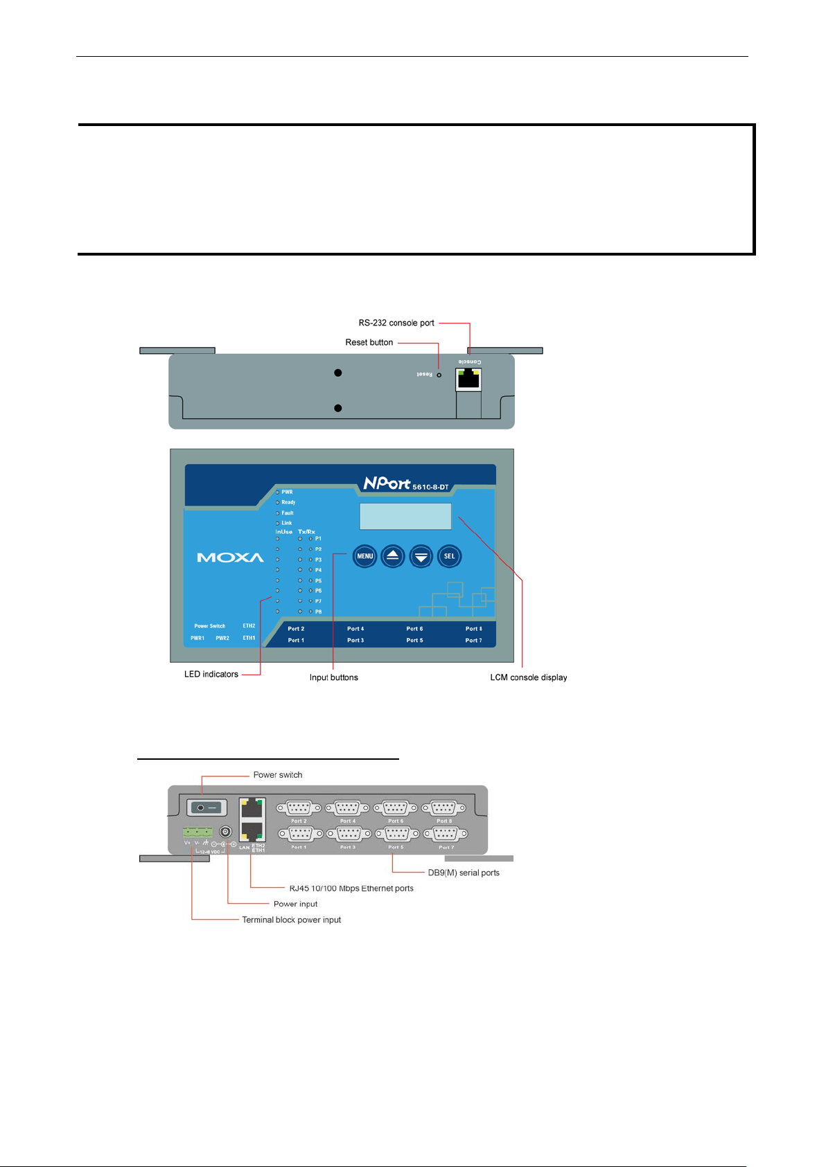
Top and Rear Views
DT and DT-J models:
Front Views
NPort 5610-8-DT, 5650-8-DT, 5650I-8-DT
Page 11
NPort 5600-8-DT/DTL Series Overview of Hardware
2-3
www.ipc2u.ru
www.moxa.pro
NPort 5610-8-DT-J, 5650-8-DT-J
Bottom View
Item Description
PWR LED Indicates power input status (red)
Ready and Fault LEDs Indicates normal operation (green) or IP conf lic t (re d )
Link LED Flashes when Ethernet is connected
InUse LED s Flashes when device port is transmitting or rece iving data (green)
Device port Tx LEDs Flashes when device port is transmitting data (g re e n)
Device port Rx LEDs Flashes when device port is receiving data (orang e )
Power input For power jack connection to AC power source here
Ethernet port For Ethernet network cable connection
DB9(M) serial ports For attachment of seria l devices
Reset button Press and hold with a pointed object for 5 seconds to load factory defaults
Page 12
NPort 5600-8-DT/DTL Series Overview of Hardware
2-4
NOTE
The figures in this section apply to the follow ing
•
•
•
•
•
•
www.ipc2u.ru
www.moxa.pro
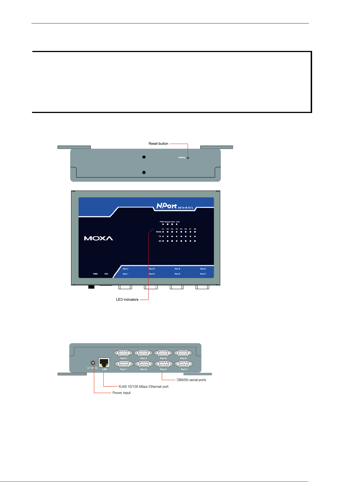
Panel Layout (DTL and DTL-T models)
NPort 5610-8-DTL
NPort 5650-8-DTL
NPort 5650I-8-DTL
NPort 5610-8-DTL-T
NPort 5650-8-DTL-T
NPort 5650I-8-DTL-T
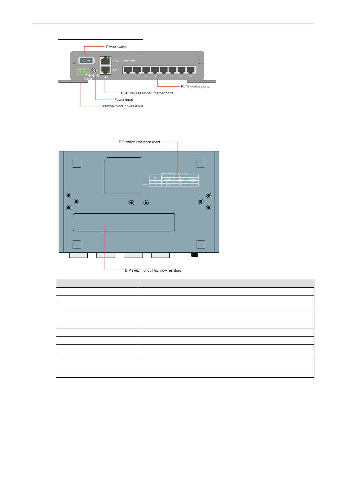
Top and Rear Views
DTL and DTL-T models:
Front View
Page 13
NPort 5600-8-DT/DTL Series Overview of Hardware
2-5
www.ipc2u.ru
www.moxa.pro
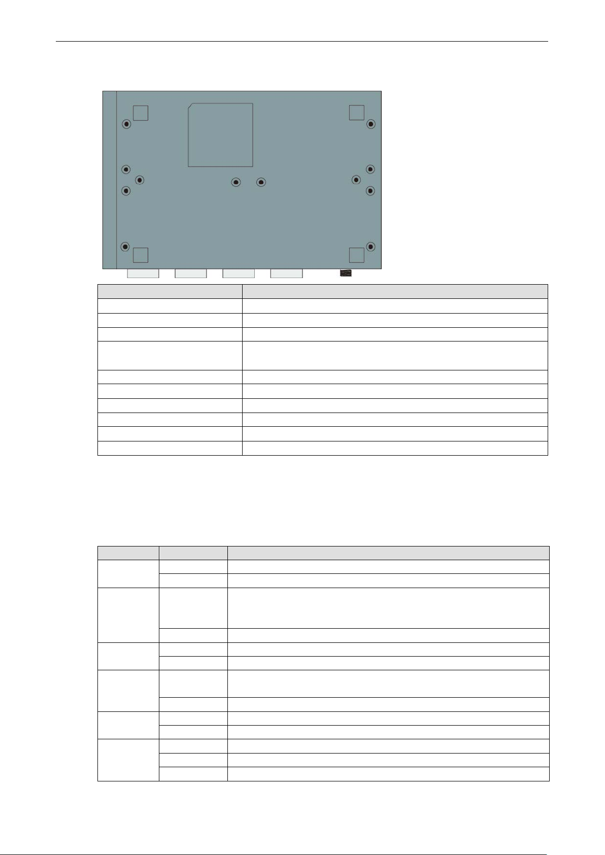
Bottom View
Item Description
PWR LED Indicates power input status (red)
Ready and Fault LEDs Indicates normal operation (green) or IP conflict (red)
Link LED Flashes when Ethernet is connected
InUse LED s Flashes when device port is transmitting or rece iving data (green)
Device port Tx LEDs Flashes when device port is transmitting data (g ree n)
Device port Rx LEDs Flashes when device po rt is receiving data (orange)
Power input For power jack connection to AC power source here
Ethernet port For Ethernet network cable connection
DB9(M) serial ports For attachment of serial devices
Reset button Press and hold with a pointed object for 5 seconds to load factory defaults
LED Indicators
Top Panel Indicators
Name Color Function
PWR red Power is on.
off Power is off.
Ready green Steady: The NPort is operational.
off Power is off or fault condition exists.
Fault red IP conflict or DHCP or BOOTP server did not respond properly.
off No fault condition detected.
Link green Steady: Network is connected, no data is being transmitted.
off Ethernet cable is disconnected or has a short.
InUse
(P1 to P8)
Tx/Rx
(P1 to P8)
green Serial port has been opened by serve r side so ftwa r e.
off Serial port is not currently opened by server side software.
green (Tx) Serial device is transmitting data.
orange (Rx) Serial device is receiving data.
off No data is flowing to or from the serial port.
Blinking: The NPort is responding to NPort Administrator’s “Locate” function
or the NPort is resetting to the factory default.
Blinking: Network is connected, data is being trans mitte d.
Page 14
NPort 5600-8-DT/DTL Series Overview of Hardware
2-6
A green LED indicates a valid connection to a 100 Mbps Ethernet networ k .
An orange LED indicates a valid connection to a 10 Mbps Etherne t ne twork .
3
TxD
RxD+(B)
Data+(B)
6
DCD
RxD-
Data-
www.ipc2u.ru
www.moxa.pro
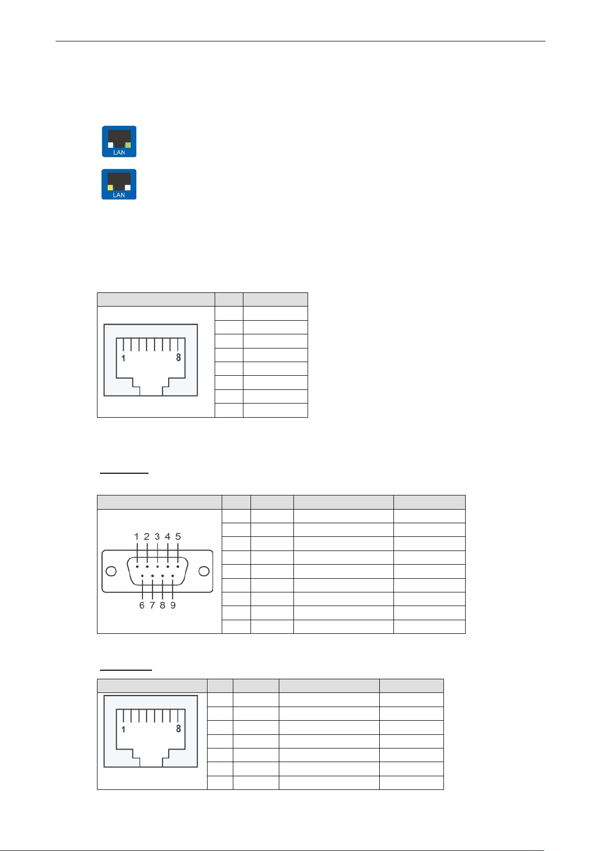
Ethernet Port Indicators
Two LED indicators are built into each 10/100 M Ether ne t connecto r. A valid network connection will be
indicated as follows:
Pin Assignments
Ethernet Port Pinouts
RJ45 Connector Pin Signal
1 RXD+
2 RXD3 TXD+
4 –
5 –
6 TXD7 –
8 –
Device Port Pinouts
DB9 Ports (NPort 5610-8-DT, 5650-8-DT, 5650I-8-DT, 5610-8-DTL/DTL-T, 5650-8-DTL/DTL-T, and
5650I-8-DTL/DTL-T)
DB9 Male Connector Pin RS-232 RS-422/RS-485-4w RS-485-2w
The NPort 5610-8-DT and 5610-8-DTL only support RS-232 signals.
RJ45 Ports (NPort 5610-8-DT-J, 5650-8-DT-J)
RJ45 Connector Pin RS-232 RS-422/RS-485-4w RS-485-2w
1 DCD TxD-(A) –
2 RxD TxD+(B) –
4 DTR RxD-(A) Data-(A)
5 GND GND GND
6 DSR – –
7 RTS – –
8 CTS – –
9 – – –
1 DSR – –
2 RTS TxD+ –
3 GND GND GND
4 TxD TxD- –
5 RxD RxD+ Data+
7 CTS – –
Page 15

NPort 5600-8-DT/DTL Series Overview of Hardware
2-7
1
DSR
Ethernet Interface
Number of Ports:
Speed:
Connector:
Magnetic Isolat ion P ro tec t i o n:
Serial Interface
Number of Ports:
Serial Standards:
NPort 5610
NPort 5650-8-DT: RS-232/422/485
Connector:
NPort
NPort 5610
Serial Line Protection:
15 KV ESD protection for all signals
2 KV isolation protection (NPort 5650I
RS
Pull High/Low Resistor for RS
Terminator for RS
Serial Communication Pa ra me te rs
Data Bits:
Stop Bits:
Parity:
Flow Control:
Baudrate:
Serial Signals
RS
RS
RS
RS
Software
www.ipc2u.ru
www.moxa.pro
8 DTR – –
The NPort 5610-8-DT-J only supports RS-232 signals.
Console Port Pinouts (applies only to DT models)
RJ45 Connector Pin RS-232
2 RTS
3 GND
4 TxD
5 RxD
6 DCD
7 CTS
8 DTR
Product Specifications
NPort 5600-8-DT
2 (1 IP)
10/100 Mbps, auto MDI/M DIX
8-pin RJ45
8
-8-DT: RS-232
5610-8-DT/5650-8-DT/5650I-8-DT: DB9 m a le
-8-DT-J/5650-8-DT-J: RJ45 (8 pins)
-485 Data Direction Control: ADDC® (automatic data direction control)
-485: 120 Ω
1.5 KV built-in
-8-DT only)
-485: 1 KΩ, 150 KΩ
5, 6, 7, 8
1, 1.5, 2
None, Even, Odd, Space, Mark
DSR/DTR and RTS/CTS (RS-232 only), XON/XOFF
50 bps to 921.6 Kbps
-232: TxD, RxD, RTS, CTS, DTR, DSR, DCD, GND
-422: Tx+, Tx-, Rx+, Rx-, GND
-485-4w: Tx+ , Tx-, Rx+, Rx-, GND
-485-2w: Data+, Data-, GND
Page 16

NPort 5600-8-DT/DTL Series Overview of Hardware
2-8
Network Protocols: ICMP, IP, TCP, UDP, DHCP, BOOTP, Telnet, DNS, SNMP V1, HTTP, SMTP, SNTP, Rtelnet,
ARP, RFC2217
Configuration Options:
Windows Real COM Drivers:
Windows 2012 x64, Embedded CE 5.0/6.0, XP Embedded
Fixed TTY Drivers:
Solaris 10, FreeBSD, AIX 5.x, HP
Linux Real TTY Drivers:
Mini Screen with P ush Buttons
LCD Panel:
Push Buttons:
Physical Characteristics
Housing:
Weight:
NPort 5610
NPort 5610
NPort 5650
NPort 5650
NPort 5650I
Dimensions:
Without ears: 197 x 44 x 125 mm (7.76 x 1.73 x 4.92 in)
With ears: 229 x 46 x 125 mm (9.01 x 1.81 x 4.92 in)
With DIN
Environmental Limits
Operating Temperatur e:
Storage Temperature:
Ambient Relative Humidity:
Power Requirements
Input Voltage:
Power Consumption:
NPort 5610
NPort 5610
NPort 5650
NPort 5650I
NPort 5650
Standards and Certifications
Safety:
EMC:
EMI:
EMS: EN 55024
Reliability
Alert Tools:
Automatic Reboot Trigger:
MTBF (mean time between fai lures):
Warranty
Warranty Period: 5 years
Details:
www.ipc2u.ru
www.moxa.pro
Web Console, Telnet Console, Serial Console, Windows Utility
Windows 95/98/ME/NT/2000, Windows XP/2003/Vista/2008/7/8 x86/x64,
SCO Unix, SCO OpenServer, UnixWare 7, UnixWare 2.1, SVR 4.2, QNX 4.25, QNX 6,
-UX 11i
Linux kernel 2.4.x, 2.6.x, 3.x
Liquid Crystal Display on the case
Four push buttons for convenient on-site configur ation
Metal, IP30 protection
-8-DT: 1760 g
-8-DT-J: 1710 g
-8-DT: 1770 g
-8-DT-J: 1710 g
-8-DT: 1850 g
-Rail kit on bottom panel: 197 x 53 x 125 mm (7.76 x 2.09 x 4.92 in)
0 to 55°C (32 to 131°F)
-20 to 70°C (-4 to 158°F)
5 to 95% (non-condensing)
12 to 48 VDC
-8-DT:
611 mA @ 12 V, 300 mA @ 24 V, 140 mA @ 48 V
-8-DT-J:
611 mA @ 12 V, 300 mA @ 24 V, 140 mA @ 48 V
-8-DT:
615 mA @ 12 V, 300 mA @ 24 V, 156 mA @ 48 V
-8-DT:
1066 mA @ 12 V, 510 mA @ 24 V, 200 mA @ 48 V
-8-DT-J:
615 mA @ 12 V, 300 mA @ 24 V, 156 mA @ 48 V
UL 60950-1, EN 60950 -1
CE, FCC
EN 55022 Class A, FCC Part 15 Subpart B Class A
Built-in buzzer and RTC (real-time clock)
See www.moxa.com/warranty
Built-in WDT (watchdog timer)
163,356 hrs
Page 17

NPort 5600-8-DT/DTL Series Overview of Hardware
2-9
Ethernet Interface
Number of Ports:
Speed:
Connector:
Magnetic Isolat ion P ro tec t i o n:
Serial Interface
Number of
Serial Standards:
NPort 5610
NPort 5650-8-DTL/5650I-8-DTL: RS-232/422/485
Connector:
Serial Line Protection:
15 KV ESD protection for all signals
2 KV isolation protection (NPort 5650I
RS
Pull High/Low Resistor for RS
Terminator for RS
Serial Communication Pa ra me te rs
Data Bits:
Stop Bits:
Parity:
Flow
Baudrate:
Serial Signals
RS
RS-422: Tx+, Tx-, Rx+ , Rx-, GND
RS
RS
Software
Network Protocols: ICMP, IP, TCP, UDP, DHCP, BOOTP, Telnet, DNS, SNMP V1, HTTP, SMTP, SNTP, Rtelnet,
ARP, RFC2217
Configuration Options:
Windows Real COM Drivers:
Windows 2012 x64, X P Emb ed ded
Fixed TTY Drivers:
Solaris 10, FreeBSD, AIX 5.x, HP
Linux Real TTY Drive
Physical Characteristics
Housing:
Weight:
NPort 5610
NPort 5650
NPort 5650I-8-DTL: 1850 g
Dimensions:
Without ears: 197 x 44 x 125 mm (7.76 x 1.73 x 4.92 in)
With
With DIN
Environmental Limits
Operating Temperatur e:
Standard Models: 0 to 60°C (32 to 140°F)
Wide Temp. Models:
www.ipc2u.ru
www.moxa.pro
NPort 5600-8-DTL
1
10/100 Mbps, auto MDI/M DIX
8-pin RJ45
1.5 KV built-in
Ports: 8
-8-DTL: RS-232
DB9 male
-8-DTL only)
-485 Data Directio n Control: ADDC® (automatic data direction control)
-485: 1 KΩ, 150 KΩ
-485: 120 Ω
5, 6, 7, 8
1, 1.5, 2
None, Even, Odd, Space, Mark
Control: DSR/DTR and RTS/CTS (RS-232 only), XON/XOFF
50 bps to 921.6 Kbps
-232: TxD, RxD, RTS, CTS, DTR, DSR, DCD, GND
-485-4w: Tx+ , Tx-, Rx+, Rx-, GND
-485-2w: Data+, Data-, GND
Web Console, Telnet Console, Serial Console, Windows Utility
Windows 95/98/ME/NT/2000, Windows X P/200 3/Vista/2008/7/8 x86/x64,
SCO Unix, SCO OpenServer, UnixWare 7, UnixWare 2.1, SVR 4.2, QNX 4.25, QNX 6,
-UX 11i
rs: Linux kernel 2.4.x, 2.6.x, 3.x
Metal, IP30 protection
-8-DTL: 1760 g
-8-DTL: 1770 g
ears: 229 x 46 x 125 mm (9.01 x 1.81 x 4.92 in)
-Rail kit on bottom panel: 197 x 53 x 125 mm (7.76 x 2.09 x 4.92 in)
-40 to 75°C (-40 to 167°F)
Page 18

NPort 5600-8-DT/DTL Series Overview of Hardware
2-10
Storage Temperature:
Ambient Relative Humidity:
Power Requirements
Input Voltage:
Power Consumption:
NPort 5610
NPort 5650
NPort 5650I
Standards and Certifications
Safety:
EMC:
EMI:
EMS:
Reliability
Alert Tools: Built-in buzzer and RTC (real-time clock)
Automatic Reboot Trigger:
Warranty
Warranty Period:
Details:
www.ipc2u.ru
www.moxa.pro
-40 to 85°C (-40 to 185° F)
5 to 95% (non-condensing)
12 to 48 VDC
-8-DTL:
340 mA @ 12 V, 180 mA @ 24 V, 110 mA @ 48 V
-8-DTL:
470 mA @ 12 V, 250 mA @ 24 V, 140 mA @ 48 V
-8-DTL:
740 mA @ 12 V, 370 mA @ 24 V, 220 mA @ 48 V
UL 60950-1, EN 60950 -1
CE, FCC
EN 55022 Class A, FCC Part 15 Subpart B Class A
EN 55024
Built-in WDT (watchdog timer)
5 years
See www.moxa.com/warranty
Page 19

3
www.ipc2u.ru
www.moxa.pro
3. Basic Installation
NPort 5600-8-DT/DTL device servers are desig ned to coordinate b e twee n your network , your hos t computer,
and your serial device. Installation of the device server should occur in stages to ensure that each connection
is recognized. This chapter will guide you through a typical installation with a Windows PC. For certain
applications or environments, you may be guided to o the r chapte rs for additional information.
The following topics are covered in this chapter:
Before You Begin
Required Items
Wiring Guidelines
STEP 1: Connect network, serial device, and power
Connect to Network
Attach Serial Device
Connect Power
STEP 2: Configure the device server’s general settings
Install NPort Administrator
Search for Device Server on LAN
Adjust General Settings
Verify Network Settings
STEP 3: Configure device port operati on mode
Adjust Operation Mode Settings
STEP 4: Configure serial communica tio n par a mete rs
Review Serial Parameters
Adjust Serial Parameters
STEP 5: Map COM port to device
Specify Target Device Server
Assign COM Port Number to Device Port
Apply Change
Page 20

NPort 5600-8-DT/DTL Series Basic Installation
3-2
www.ipc2u.ru
www.moxa.pro
Before You Begin
This chapter will walk you through the major steps of a typical installation and will offer advice on adjustments
and options for specific applications. Please note that certain procedures will vary for your specific application
and environment.
In these instructions, a Windows PC is used for configuration. For Linux or UNIX environments, please refer to
Chapter 11.
Installation of the NPort 5600-8-DT/DTL is presente d in the fo llowing steps:
Step 1: Connect power, network and serial devices
Step 2: Configure the device server’s IP settings
Step 3: Configure each port’s operation mode
Step 4: Configure each port’s serial communication settings
Step 5: Map host COM ports to device ports (for Real COM mode)
Required Items
Make sure that you have the following items before beginning your installation:
• NPort 5600-8-DT/DTL device server
• Windows PC with live connection to the network (see Chap ter 11 for Linux /U NI X install ations)
• NPort Documentation & Software CD
• Ethernet cable
• Serial cable for device attachment
• Power adapter and power cord
• Make sure that you have the following information available before beginning your installation:
• IP address of your Windows PC
• IP address and subnet to be assigned to the device server
• TCP or UDP port number to be used for each device port
• Local COM port number to be used for each device port (for Real COM mode)
• Baudrate, parity, data bit, and stop bit settings for each device port
Wiring Guidelines
The following guidelines will help ens ure trouble-free signal communication with th e device ser ver.
• Use separate paths to route wiring for power and devices to avoid inte rf er e nc e . Do not run signal or
communication wiring and power wiring in the same wire conduit. The r ul e of thumb is that wir ing that
shares similar electrical characteristics can be bundled together.
• If power wiring and device wiring paths must cross, make sure the wires are perpendicular at the
intersection point.
• Keep input wiring and output wiring separate.
• Label all wiring to each device in the system for easier testi ng and tr oubleshooting
Page 21

NPort 5600-8-DT/DTL Series Basic Installation
3-3
ATTENTION
Wiring Safety Preca ut i on s:
Disconnect power source
Do not install or wire this unit or any attached devices with the power connected. Disconnect the power before
installation by removing
Follow maximum current ratin gs
Calculate the maximum possible curre nt in each power wire and com mon wire . Observe all elec trical codes
dictating the maximum current allowab le for ea c h wire siz e .
If
equipment.
Use caution
The unit will generate heat during operation, and the casing may feel hot to the touch. Take care when handling
unit. Be sure to leave adequate space for ventilation.
www.ipc2u.ru
www.moxa.pro
the current goes above the maximum ratings, the wiring could overheat, causing serious damage to your
- unit may get h ot
the power cord before installing and/or wiring your unit.
STEP 1: Connect network, serial device, and power
This step covers the physical installation of the har dwa re. This ste p r equi r es the follo w ing item s :
• NPort 5600-8-DT/DTL device server
• Power ada pter and power cord
• Ethernet cable
• Serial cable with RJ45 or DB9 connector (depending on model)
• Serial device
Connect to Network
After placing the device server in its location, plug one end of the network cable into one of the device server’s
Ethernet ports. Plug the other end of the cable to the network. Ther e are two Ether ne t ports on the NPort
5600-8-DT/DTL so you can easily daisy-chain multiple units together (the NPort 5600-8-DTL has one Ethernet
port only).
Attach Serial Device
Use the serial cable to connect your serial device to a device port on the NPort 5600-8-DT/DTL. Make sure that
you are familiar with your device’s serial communication settings (e.g., baudrate, stop bit, etc.). You will need
to know these parameters when configuring the device server and drivers.
Adjustable Pull High/Low Resistors for RS-485
Termination resistors may be needed when connecting RS-485 devices to your NPort, in order to prevent the
reflection of serial signals. The device port’s pull high/low resistors must then be set correctly t o prevent signal
corruption.
• NPort 5600-8-DT: Use the DIP switches on the bottom panel to configure each device port’s pull high/low
resistors. You will need to unscrew the DIP switch cover to access the DIP switc he s .
Page 22

NPort 5600-8-DT/DTL Series Basic Installation
3-4
Default
ATTENTION
Do not use the 1 KΩ setting when using RS
maximum allowed communicati
Grounding and wire routing helps limit the effe c ts of noise due to elec tro m agnetic inte rference (EMI). Before
attaching any serial devices, run your ground wir e from your grounding surface to the device server’s
gro
www.ipc2u.ru
www.moxa.pro
• NPort 5600-8-DTL: Remove the top cover to access the DIP switches used to configure each device port’s
pull high/low resistors (note that SW4 is reserv e d for futur e use ).
The pull high/low resistor values for each device port are set as follows:
SW 1 2 3
Pull High Pull Low Terminator
ON
OFF
1 KΩ 1 KΩ 120 Ω
150 KΩ 150 KΩ
unding contact at the rear panel. Secure the connection with the prov ided screw.
on distance, and the Rx LED may light up.
-232. Doing so will degrade the RS-232 signals, shorten the
Connect Power
Connect the 12 to 48 VDC power line to the NPort 5600-8-DT/DTL’s terminal block or power jack. The “Ready”
LED will initially glow red. When the syste m is ready , the “Ready” LED will turn gr e e n.
STEP 2: Configu re the device server ’ s g en eral settings
This step covers the configuration of genera l setting s us ing NPor t Adm inis trator. You may also use the web,
serial, Telnet, or LCM console to configure the device server. Please refer to Chapter 7, 8, and 10 for additional
information on using the other consoles.
This step requires the following item s :
• NPort 5600-8-DT/DTL dev i ce serve r w ith live conne c tion to the network
• Windows PC with live connection to the same network (see Chapte r 11 for Linux /UNI X installations)
• NPort Documentation & Software CD
Install NPort Administrator
Locate and run the setup program on the NPort Document & Software CD. The setup program will b e name d
Npadm_Setup_[Version]_Build_[DateTime].exe (e.g., “Npadm_Setup_Ver1.8_
Build_07041316.exe”). Run NPort Administrato r w hen installat io n is co mp l e te .
Page 23
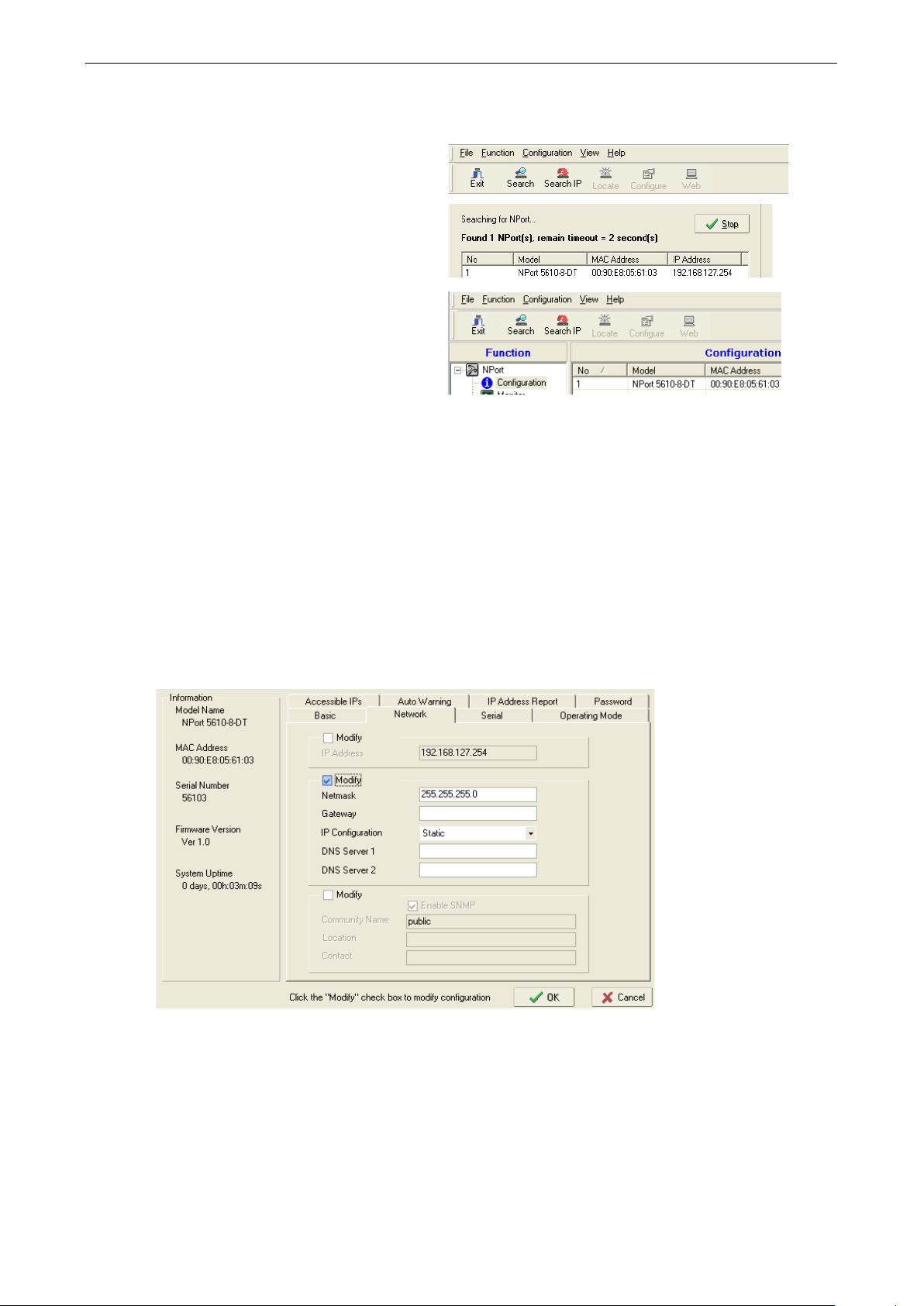
NPort 5600-8-DT/DTL Series Basic Installation
3-5
In NPort Administrator, click “Sear c h” to
search your LAN for NPort device servers.
When your unit appears in the search results,
you may click “Stop” to end the search. You
may also wait a few more moments for the
search to complete.
The “Configuration” panel will list the N Po rt
device servers that were found on the LAN. If
your unit cannot be found, you may
network problem. Please check all cables and
verify that your PC and device server are on
the same LAN. If you still have problems, try
connecting the device server directly to your
PC.
www.ipc2u.ru
www.moxa.pro
Search for Device Server on LAN
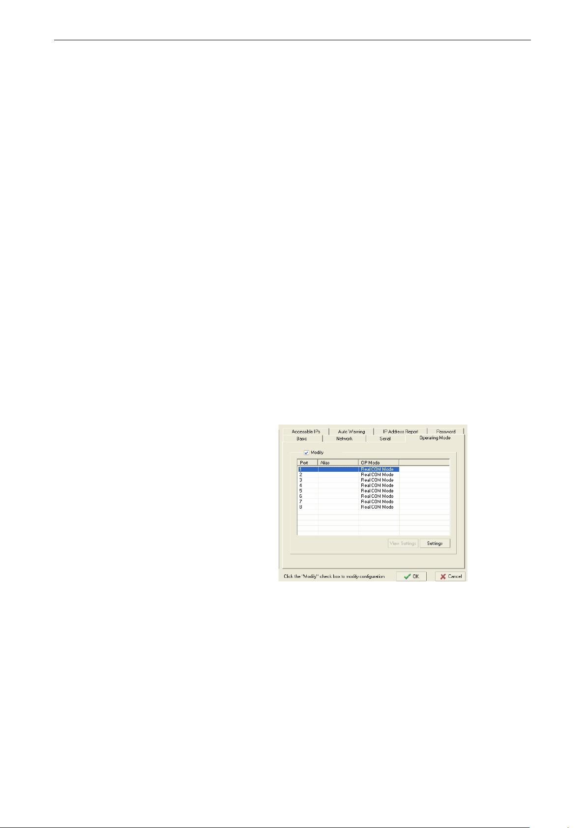
Adjust General Settings
Right-click your unit in the “Configur ati o n” panel and se le c t “Configure” in the context menu. If your device
server is password protected, first select “Unlock” in the context menu.
In the configuration window, go to the “Network” tab. For any parameter that you wish to change, click the
appropriate “Modify” box and make the desired adjus tm e nts. The dev ic e serve r mus t be assigne d a valid,
unique IP address for operation in your network. Both fixed and dynamic IP addresses are supported. Please
consult with your network administrator if yo u are not sure how to set these parameters.
When you are ready to restart the device server with the new settings, click “OK” .
have a
Static IP Addresses
For most applications, you will assign a fixed IP address to the device server. To assign a static (fixed) IP
address, the “IP Configuration” parameter must be set to “Static”, which is the default setting. You may then
modify the “IP Address” and “Netmask” parameters.
Dynamic IP Addresses
For certain network environments, your device server’s IP address will be assigned by a DHCP or BOOTP se rver.
In this case, instead of assigning the device server’s IP address, you will need to configure the device server to
receive its IP address from the appropriate server. Set the “IP Configuration” parameter to “DHCP”, “BOOTP”,
Page 24
NPort 5600-8-DT/DTL Series Basic Installation
3-6
The operat
device port can be configured through NPort
Administrator. Open your device serv er’ s
configuration window using the same
method when you adjusted the network
parameters. On the “Operation Modes” tab,
click “Modify” and select the device port that
you wish to configure. Click “Settings” to
configure the selected device port.
www.ipc2u.ru
www.moxa.pro
or “DHCP/BOOTP”, depending on your network environment. The “IP Address” and “Netmask” parameters will
be unavailable for editing since these parame ter s will b e assig ne d auto mati c ally.
If you are not sure whether you need to configure your device server for a dynamic or static IP address, consult
the administrator who set up the LAN.
Verify Network Settings
If your device server has been configured correctly, you should be able to ping its IP address from your PC. First
make sure that your PC and device server are on the same subnet, then ping the device server’s address. If no
response is received, you will need to check your cables and networ k setting s .
STEP 3: Configure device port operation mode
This step covers configuration of a device por t’ s operation mode. The operation mode determines how the
device port will interact with the network. The sele c tion of operation mode will depend on your specific
application. Please refer to the chart on the follo w ing p age for guidanc e in sel e c ting the oper ati o n mode. For
additional information, p le ase refe r to Chapter 5.
This step requires the following item s :
• NPort 5600-8-DT/DTL dev i ce serve r w ith live conne c tion to the network
• Windows PC with live connection to the same network and NPort Adminis trator installed
Make sure that NPort Administrator is open with your device server listed in the configuration pane. You should
also have an understanding of your intended devic e netwo rking application and the appropriate settings .
Adjust Operation Mode Settings
ion mode parameters for each
Page 25

NPort 5600-8-DT/DTL Series Basic Installation
3-7
Set the operation mode and associated
parameters as necessary. Please refer to
Chapter 5 and 6 for additional information on
operation modes and advanced
When you are ready to restart the device
server with the new settings, click “OK”.
www.ipc2u.ru
www.moxa.pro
settings.
Page 26
NPort 5600-8-DT/DTL Series Basic Installation
3-8
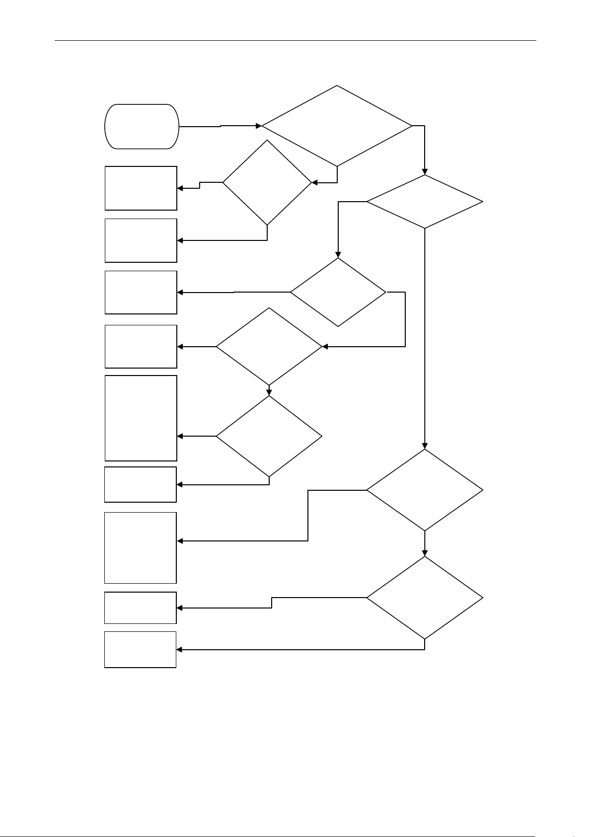
Operation Mode Selection Chart
You can use this chart to help you select the appropriate operation mode for your application.
more COM ports?
Yes
No
Moxa driver
Yes
No
Yes
No
program?
parameters?
TCP
UDP
Serve
Client
Yes
No
slave)
Yes
No
Yes
No
program?
transmission
Telnet mode
UDP
Yes
www.ipc2u.ru
www.moxa.pro
Using legacy COM
Start
software? Need
Real COM
mode with
Using
Moxa
driver?
RFC2217
mode with 3
UDP mode
TCP Client
mode
RFC2217
mode
TCP Server
mode with IP
Serial Library
or
rd
Server
or client
Need to
control serial
TCP or UDP
application
Using socket
TCP Server
mode
Pair
Connection
modes
(master +
Reverse
Contact Moxa
for guidance
Need to
extend serial
Console
management
application?
Page 27

NPort 5600-8-DT/DTL Series Basic Installation
3-9
2
RS-485-4W
www.ipc2u.ru
www.moxa.pro
STEP 4: Configure serial communication parameters
This step covers the configuration of each device port’s serial communication parameters, such as baudra te ,
stop bit, etc.
This step requires the following item s :
• NPort 5600-8-DT/DTL dev i ce serve r w ith live conne c tion to the network
• Windows PC with live connection to the same network and NPort Administrator installed
Make sure that NPort Administrator is open with your device server listed in the configuration pane. You should
also know the serial communication paramete rs for the attac he d devic e and intended application.
Review Serial Parameters
The following parameters need to be set correctly on the device port for proper communication with your device.
Please refer to your device’s documentatio n for the approp riate settings.
Parameter Options Description
Baudrate 50 bps
115.2 Kbps (default)
921 Kbps
Data bits 5
6
7
8 (default)
Stop bits 1 (default)
1.5
This is the rate of data transmission to and from the
attached serial device.
This is the size of each data character.
This is the size of the stop character.
Parity None (default)
Even
Odd
Space
Mark
Flow control None
RTS/CTS (default)
DTR/DSR Xon/Xoff
FIFO Enable (default)
Disable
Interface RS-232 (default)
RS-422
RS-485-2W
Adjust Serial Parameters
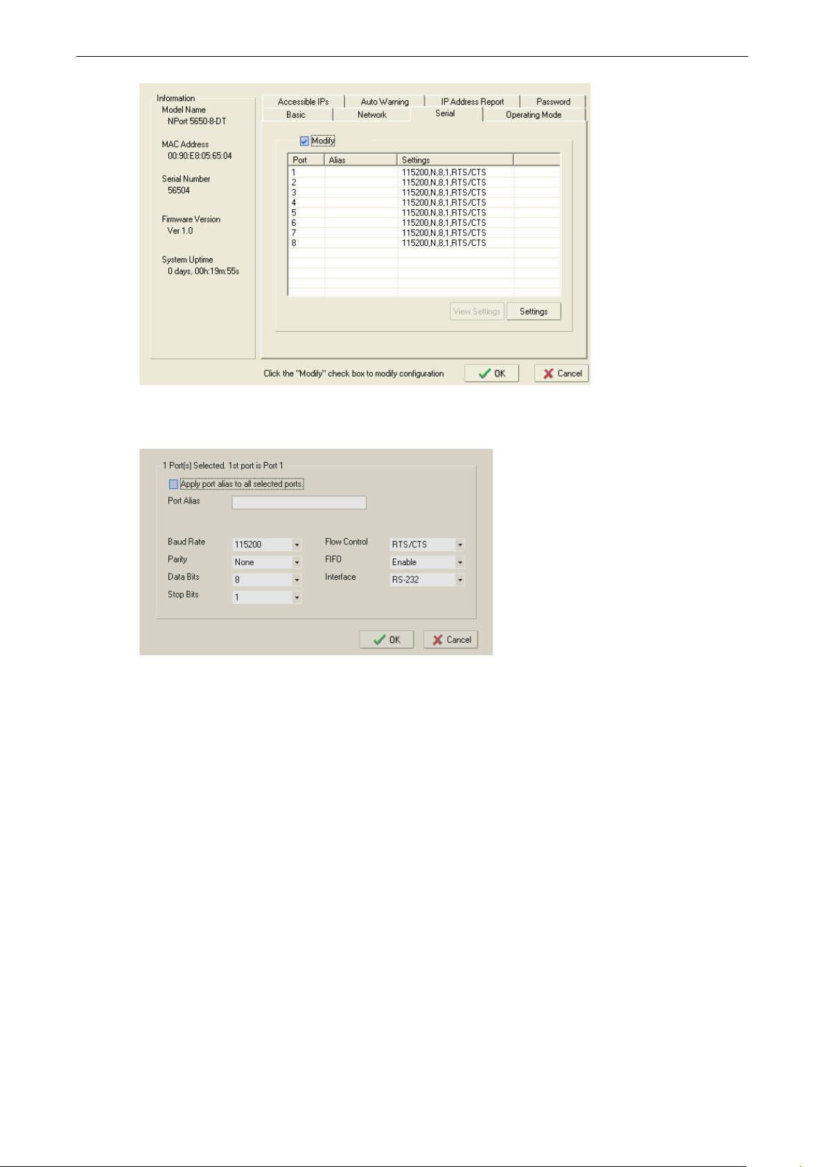
The serial communication parameters for eac h devic e por t can be config ured thro ug h N Por t Adm inis trator.
Open your device server’s configuratio n wind ow us ing the same method when yo u adjus ted the netw ork
parameters. On the “Serial” tab, click “ Modi fy ” and sele c t the dev ic e por t that you wis h to config ure . C lick
“Settings” to configure the selected devic e port.
This is the kind of parity that will be used. Even and
Odd parity provide rudimentary error-checking; Space
and Mark parity are rarely used.
This is the method used to suspend and resume data
transmission to ensure that data is not lost. RTS/C TS
(hardware) flow control is recommended if pos s ib le .
This controls whether the device port’s built-in
128-byte FIFO buffer is used. When enabled, the FIFO
helps reduce data loss regardless of directi on .
This is the serial interface that will be used. The
options that are available depend on the specific model
of devic e server.
Page 28
NPort 5600-8-DT/DTL Series Basic Installation
3-10
www.ipc2u.ru
www.moxa.pro
Make adjustments to the parameters as necessary. When you are ready to restar t the dev ic e serv er with the
new settings, click “OK”.
STEP 5: Map COM port to device
This step covers the mapping of COM ports on a Windows PC to NPort device ports. T his allow s Windo w s
software to access serial devices over the network as if they were lo c al CO M devices, fo r instant de vice
networking without software migration. COM mapping is supported in Real COM and RFC2217 modes only.
The following instructions are for dev ice ports oper a ting in Real COM mode. For device ports operating in
RFC2217 mode, follow the instructions for your particular driver. Real COM mode also supports TTY port
mapping in Linux and UNIX systems.
This step requires the following item s :
• NPort 5600-8-DT/DTL dev i ce serve r w ith the following:
Liv e conne c ti o n to the network
Device port configured for Real COM operation
• Windows PC with the following:
Liv e conne c ti o n to the same network
NPort Administrator installed
S of tw are for intended serial application installe d
Make sure that NPort Administrator is open with your device server listed in the configuration panel. You should
also know the serial com municatio n p aram e te rs for the attac he d device and intended application.
Page 29
NPort 5600-8-DT/DTL Series Basic Installation
3-11
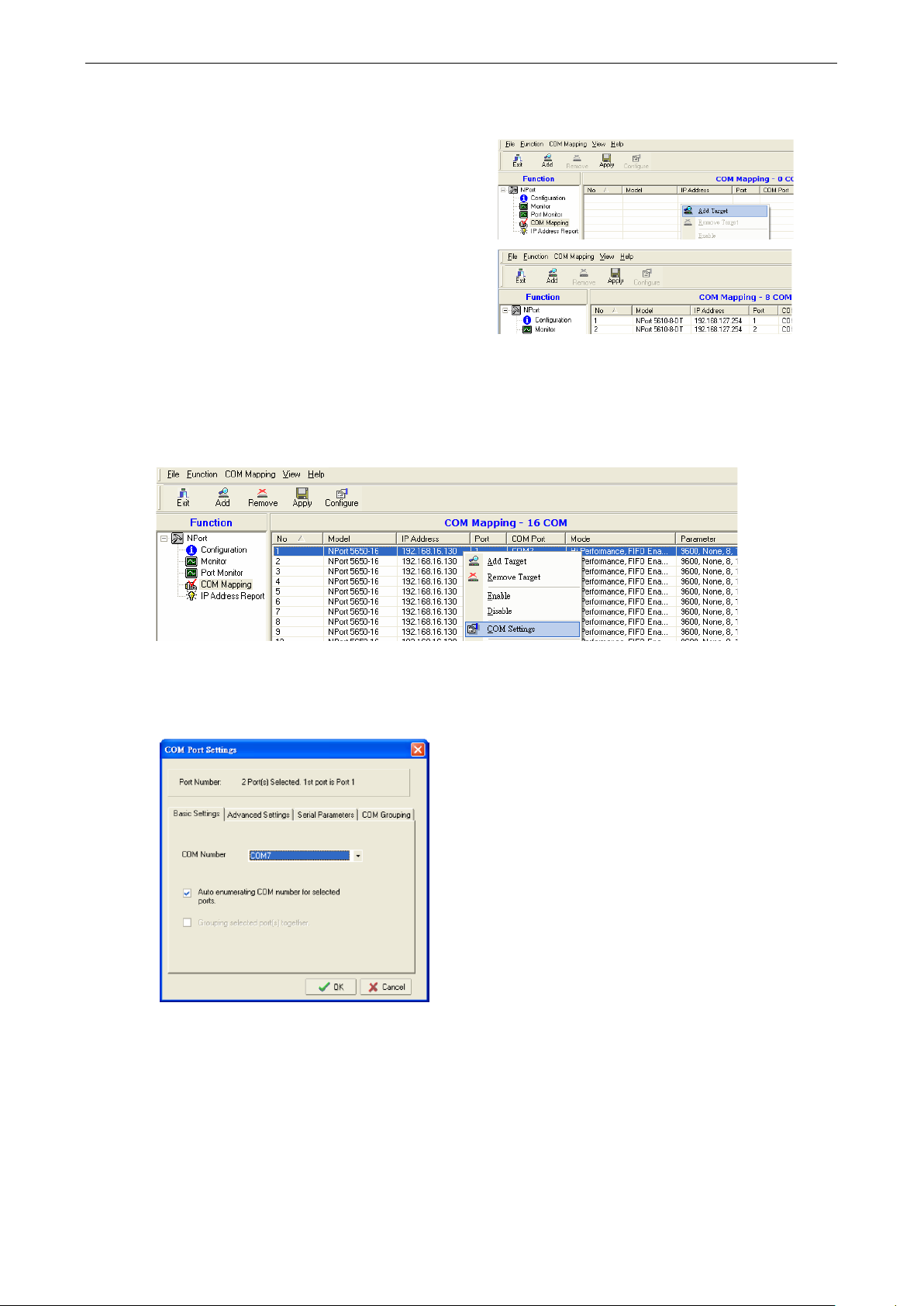
In NPort Administrator, click “COM Mapping ” in the
Function panel to open the COM Mapping window.
Right
indow
and select “Add Target” in the context menu to assign
your device server as the mapping target.
A list of NPort device servers that have been found by
NPort Administrator will appear. Select your device
server and click “Finish”.
In the Basic Settings tab, select the COM port number that will be
multiple COM ports at the same time, in which case the “Auto Enumer a ting ” feature may be used to
automatically number the COM ports.
www.ipc2u.ru
www.moxa.pro
Specify Target Device Server
-click an empty line in the COM Mapping w
Assign COM Port Number to Device Port
The COM Mapping window will show a list of available device ports on the network. Right-click the target device
port and select “COM Settings” in the context menu.
mapped to the device port. You can map
Page 30
NPort 5600-8-DT/DTL Series Basic Installation
3-12
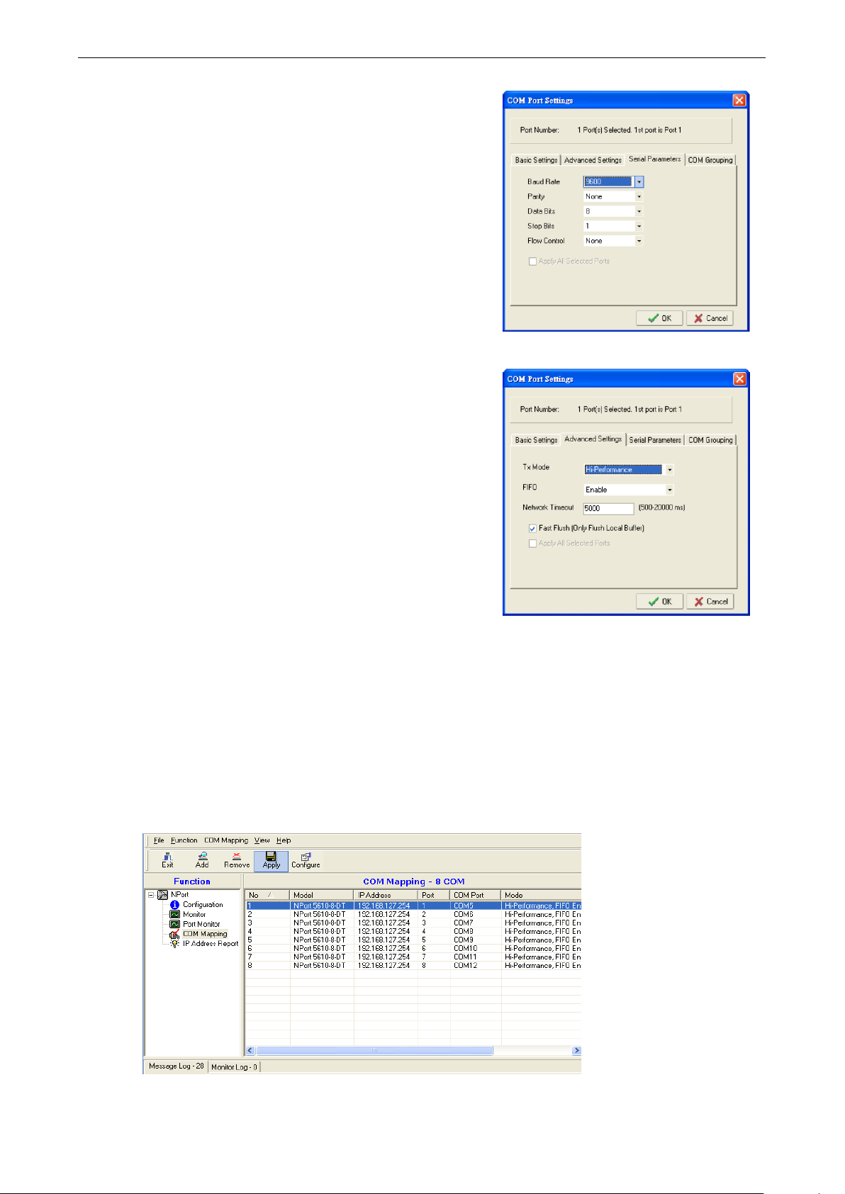
In the Serial Parameters tab, adjust the settings to match your
device. These settings , used for serial printer only, must also
match the settings on the device port. Click “OK” when you are
satisfied with your changes.
Advanced Setting s
For additional details on Advanced Setting s in NPor t
Administrator, please refer to Chapter
Tx Mode:
issues a “Tx Empty” response to the program after sending
data to the NPort. In Classical mode, the driver sends the “Tx
Empty” response after confirmation is received from the NPort.
Classical mode is recommended if you want to ensure that all
data is sent out before further processing.
FIFO:
Network Timeout: This specifies when an open, close, or serial
parameter change operation will time ou
Fast Flush:
buffer on the host for a Win32 PurgeComm() function call.
When disabled, both the local and remote buffers are flushed.
If your application uses PurgeComm() and performance seems
sluggish, try
www.ipc2u.ru
www.moxa.pro
8.
In Hi-Performance mode, the driver immediately
This tells the driver whether or not to use the FIFO.
When enabled, the driver flushes only the local
enabling Fast Flush.
Apply Change
Right-click COM Mapping in the Function pane l and sele c t “App ly Cha ng e” in the context menu to save the
current COM mapping settings. Your applicatio n w ill no w be able to acces s the targ e t ser i al devic e us ing the
COM port.
t.
Page 31

4
www.ipc2u.ru
www.moxa.pro
4. General Settings
NPort 5600-8-DT/DTL dev i ce serve rs are eas ily configured to suit your network environment and your
application. This chapter covers general settings for your device server.
The following topics are covered in this chapter:
Overview
Basic Settings
Network Settings
Serial Settings
Operating Settings
Accessible IP Settings
Auto Warning Setting s
Email and SNMP trap
Event Type
Change Password
Page 32

NPort 5600-8-DT/DTL Series General Settin gs
4-2
ATTENTION
There is a risk of explosion if the real
The real time clock is powered by a lithium battery. We strongly recommend that you obtain assistance from
a Moxa support engineer before replacing the battery. Please contact the Moxa RMA service team if you need
to change the battery.
www.ipc2u.ru
www.moxa.pro
Overview
The NPort 5600-8-DT/DTL can be configured through NPort Administrator, the web console, the Telnet console,
or the serial console. For each of these config uratio n inte rf ace s , par ame ter s are organiz e d by type . For this
chapter, screenshots from the web console are used to illustrate the available parameters, but the same
parameters can be modified using the other interf aces.
Basic Settings
Server name (default = blank): This is an optional free text field for your own use. It does not affect operation
of the NPort device server. It can be used to help differentiate o ne devic e ser ver from another.
Time zone (default = GMT Greenwich Mean Time): This field shows the currently selected time zone and
allows you to select a different time zone.
Local time: This field shows the time that you last opened or refreshed the browser, using the NPort’s built-in
real-time clock. You can adjust the real-time clock us ing this field. Make sure that you first select the correct
time zone.
-time clock battery is replaced incorrectly!
Time server (default = blank): This optional field is for your time server’s IP address or domain name, if a time
server is used in your network. The NPort 5600-8-DT/DTL supports SNTP (RFC-1769) for automatic time
calibration. The device server will r e q uest time infor m ation from the specified time server every 10 minutes.
Web console (default = Enable): This f ie ld ena b les or dis able s acce ss to the web cons o le.
Serial console (default = Enable): This field enables or disables access to the serial console (applie s to DTL
models only)
Page 33
NPort 5600-8-DT/DTL Series General Settin gs
4-3
ATTENTION
If you disable both the web console and Telnet console, you can still use the LCM console or NPort Administrator
to configure your NPort device server.
ATTENTION
You must assign a valid IP a
environment. Your network system administrator should provide you with a unique IP address and related
settings for your network
www.ipc2u.ru
www.moxa.pro
Telnet console (default = Enabl e ): This f i e ld enables or disables access to the Telnet console.
LCM password protect (default = No): This field enables or disables password protection for the LCM console.
The LCM console refers to the LCD control panel on the top panel of the device server, which may be used for
basic configuration.
Reset button protect (default = No): This field enables or disables reset butto n op erati on.
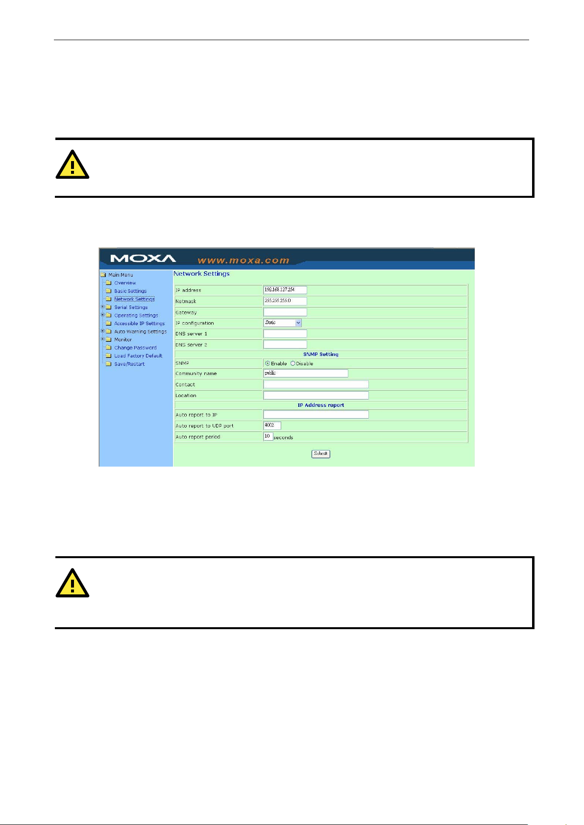
Network Settings
IP Address (default = 192.168.127.254): This field is for the IP address that will be assigned to yo ur NPor t
device server. All device ports on the device server will share this IP addres s . An IP address is a number
assigned to a network device (such as a computer) as a permanent address on the network. Computers use the
IP address to identify and talk to each other over the network. Choose a proper IP address that is unique and
valid in your network environment. If your device serv er will be assig ne d a dynamic IP addr ess, set the “IP
configuration” parameter appropriately.
Netmask (default = 255.255.255.0): This field is for the subnet mask. A subnet mask represents all of the
network hosts at one geographic location, in one building, or on the same local area network. When a packet
is sent out over the network, the NPort device server will use the subne t mask to check whether the desired
TCP/IP host specified in the packet is on the local network segment. If the addre ss is on the sam e network
segment as the device server, a connection is establishe d directly from the device server. Otherwise, the
connection is established through the g a teway as spec ified in the “Gateway” parameter.
Gateway (default = blank): This field is for the IP address of the gateway, if applicable. A gateway is a network
computer that acts as an entrance to another network. Usually, the computers that control traffic within the
network or at the local Internet service provider are gateway nodes. The NPort device server needs to know the
ddress to your NPort 5600-8-DT/DTL before it will work in your network
Page 34

NPort 5600-8-DT/DTL Series General Settin gs
4-4
Static
User-defined IP address, netmask, gateway.
assigned IP address, netmask, gateway, DNS, and time server,
(default = blank) This optional field specifies the destination IP address for the IP address
www.ipc2u.ru
www.moxa.pro
IP address of the default gateway computer in order to communicate with the hosts outside the local network
environment. Consult your network adminis trator if you do not know how to set this parameter.
IP configura tion (default = Static): This field determines how the device server’s IP address will be assigned.
Four options are available:
Option Description
DHCP DH CP server-assigned IP address, netmask, gateway, DNS, and time server
DHCP/BOOTP DHCP server-
or BOOTP server-assigned IP address (if the DHCP server does not respond)
BOOTP BOOTP server-assigned IP addre ss
DNS server 1 (default = blank): This field is for the DNS server’s IP addres s , if app lic able. This allows the
NPort device server to use domain names instead of IP addresses to access hosts.
Domain Name System (DNS) is the way that Internet domain names are identified and translated into IP
addresses. A domain name is an alphanumeric name, such as www.moxa.com, that it is usually e as i e r to
remember than the numeric IP address. A DNS server is a host that translates a text-based domain name into
an IP address in order to establish a TCP/IP connection. When the user wants to visit a particular website, the
user’s computer sends the domain name (e.g., www.moxa.com) to a DNS server to request that website’s
numeric IP address. When the IP address is received from the DNS serv er , the user’ s compute r use s that
information to connect to the website’s web server.
The NPort will play the role of a DNS client, actively querying the DNS server for the IP address associated with
a particular domain name. The following dev ic e serve r p arameters on the NPort 5600-8-DT/DTL support the
use of domain names in place of IP addresses: Time Server, Destination IP Address (in TCP Client mode), Mail
Server, SNMP Trap Server, Destination Addre ss (in Pair Connection mode), and SMTP Server.
DNS server 2: This is field is for an alternate DNS server’s IP address, if applicable.
Community name (default = public): This optional field is for the community name, which is a plain-text
password mechanism for weak authenticatio n of queries to agents of managed network devices.
Contact (default = blank): This optional field is for SNMP contact information, such as an emergency contact
name and telephone or pager number.
Location (default = blank): This optional field may be used to specify the location string for SNMP agents. This
string is usually set to the street address where the NPort is physic all y loc ate d .
IP Address Reports:
The IP Address report settings are used when the NPort’s IP address is configured by DHCP or BOOTP (i.e.,
dynamic rather than static IP address). Using the se setting s , the NPor t c a n be config ure d to send per iod ic IP
address reports to a network host. For example, if the NPort is operating as a server (TCP or UDP modes), then
the host, operating as a client, must know the NPort’s IP address. If the DHCP server assigns a new IP address
to NPort, the host needs to be notified of the NPort’s new IP address. The IP address reports can be used to
resolve this situation.
Please refer to Chapter 8 for details on receiving automatic IP reports in NPort Administrator. Please refer to
Appendix C for details on the IP report protocol.
The NPort’s IP addr e ss report must b e rece ive d by a network hos t us ing one of the following methods:
• The host is using NPort Administrator ’s IP Addr ess Repor t function.
• The host is running a user-developed application that uses the IP report protocol. Please refer to Appendix
C for information about the IP report protocol.
Auto report to IP
report.
Auto report to UDP port (default = blank): This optional field specifies the UDP port number to use when
sending IP address reports.
Auto report period (default = 10 seconds): This optional field specified how often to send IP address reports.
Page 35
NPort 5600-8-DT/DTL Series General Settin gs
4-5
ATTENTION
It is critical that the device port’s serial communication settings match the attached device. Please refer to the
user’s manual for your device to verify the serial communic ation s e ttings.
www.ipc2u.ru
www.moxa.pro
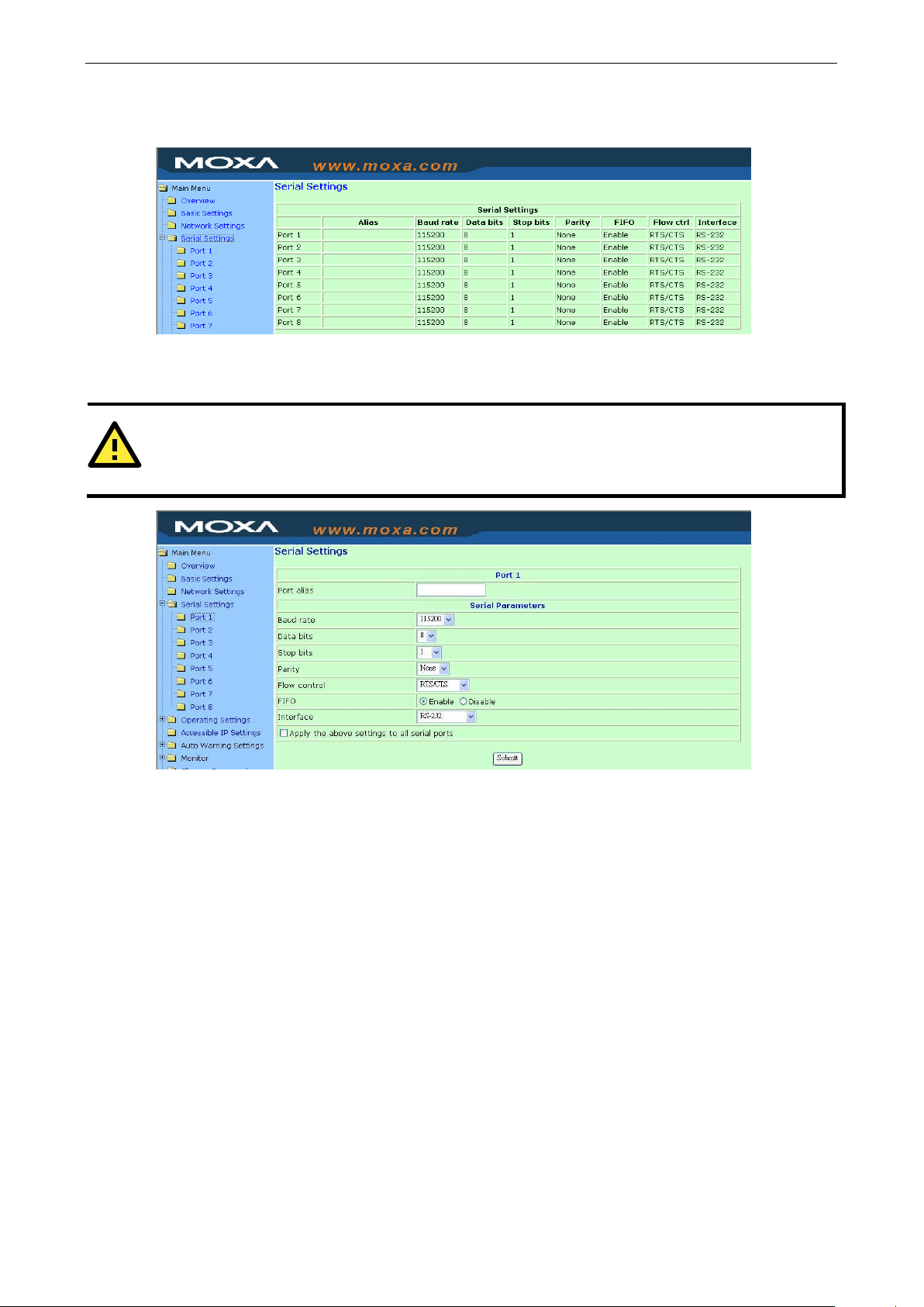
Serial Settings
Serial Settings is where you set the serial communication parameters for each device port, such as baudrate,
parity, and flow control. Each device port can be config ure d indep e ndently.
Port alias (default = blank): This optional text field can be used to help you differentiate one device port from
another.
Baudrate (default = 115.2 Kbps): This field is required.
Data bits (default = 8): This field is required.
Stop bits (default = 1): This field is required.
Parity (default = None): This a req uire d fi e ld .
Flow control (default = RTS/CTS): This is a required field.
FIFO (default = Enable): This is a required field. A 128-byte FIFO is provided for each device port in both Tx
and Rx directions. Disable the FIFO if the attached serial device does not have its own FIFO to prevent data loss
during communication.
Interface (default = RS-232): This is a required field. For the NPort 5610-8-DT/DTL an d 5610-8-DT-J, only
the RS-232 setting is available.
Page 36
NPort 5600-8-DT/DTL Series General Settin gs
4-6
www.ipc2u.ru
www.moxa.pro
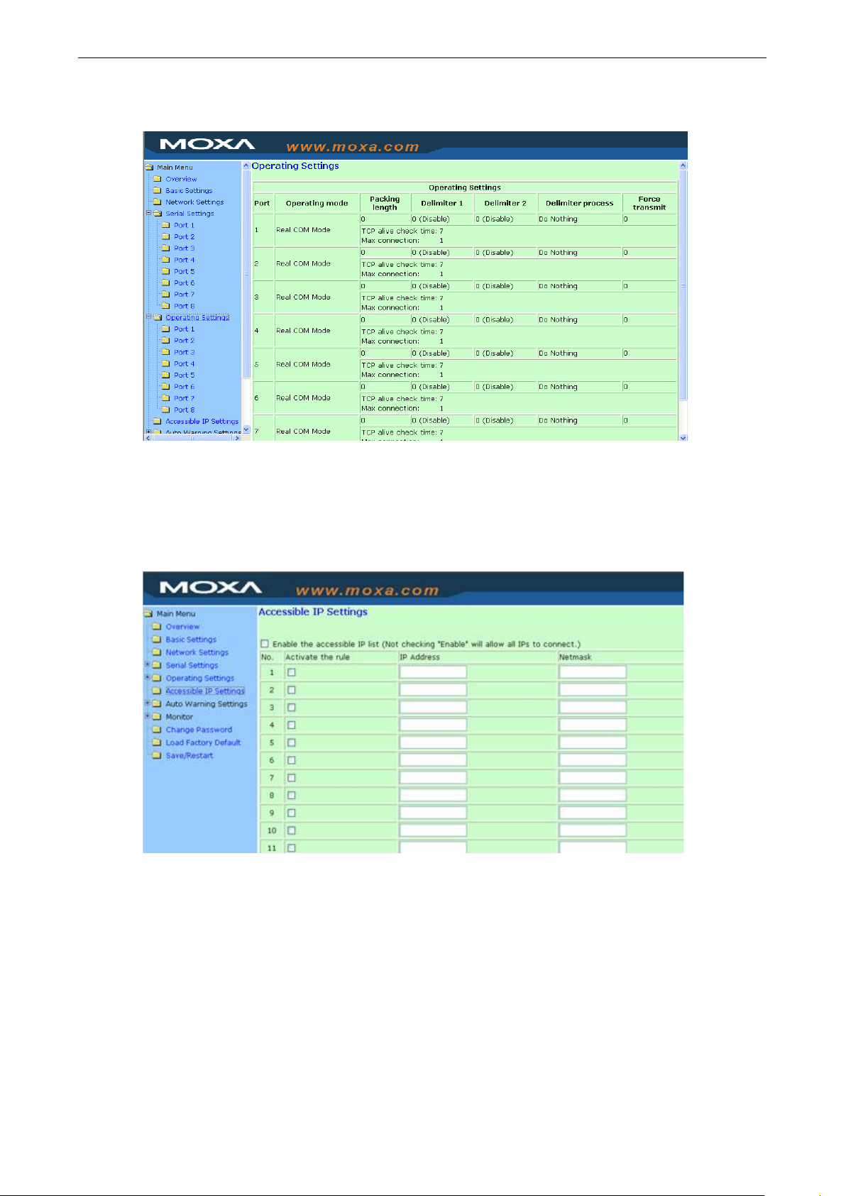
Operating Settings
Operating Settings is where each device port’s operation mode and associated parameters are conf ig ure d .
Please refer to Chapters 5 and 6 for an explanation of the different operating modes and parameters.
Accessible IP Settings
The Accessible IP list allows you enable only cer tain I P address e s to connect to the N Por t device server and
attached devices. When the accessible IP list is ena b led , only IP addre sse s that ar e on the list will b e able to
connect to the NPort. You can allow single IP addresses or a range of IP addresses by using a combination of
IP address and netmask, as follows:
• To allow access to a specific IP address
Enter the exact IP address and enter 255.255.255.255 for the netmask.
• To allow access to hosts on a specific subnet
For both the IP address and netmask, use 0 for the last digit (e.g., 192.168.1.0 and 255.255.255.0).
• To allow unrestricted access
Do not enable the accessib le IP list.
Page 37
NPort 5600-8-DT/DTL Series General Settin gs
4-7
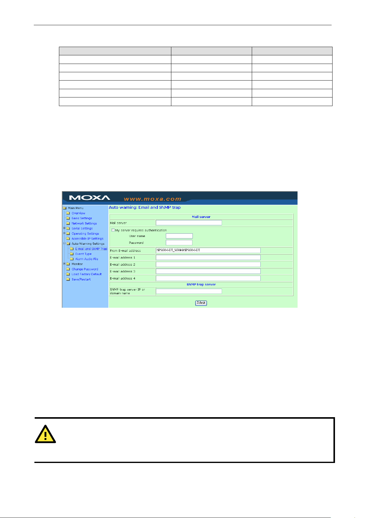
ATTENTION
Consult your network administrato r or ISP if you are unsur e how to se t the mail serve r settings. The NPort’s
automatic warning function may not work properly if the settings are incorrect. The NPort supports SMTP AUTH
with LOGIN, PLAIN, CRAM
www.ipc2u.ru
www.moxa.pro
The following table shows additional exam p le s :
Allowed hosts IP Address setting Netmask setting
Any host (disable) (disable)
192.168.1.120 192.168.1.120 255.255.255.255
192.168.1.1 to 192.168.1.254 192.168.1.0 255.255.255.0
192.168.0.1 to 192.168.255.254 192.168.0.0 255.255.0.0
192.168.1.1 to 192.168.1.126 192.168.1.0 255.255.255.128
192.168.1.129 to 192.168.1.254 192.168.1.128 255.255.255.128
Auto Warning Settings
The NPort device server can automatically warn administrators of certain system, network, and configuration
events. Depending on the event, different op tions for automatic notification are available , as shown abov e .
These options are configured in the Auto Warning Settings.
Email and SNMP trap
The Email and SNMP trap parameters are used to configure how e-mail and S NMP trap s are sent w hen an
automatic warning is issued by the NPort device serve r .
Mail Server (def ault = blank): This optional field is for the IP address or domain name of your network mail
server, if applicable. The mail server is required for the NPort to send e-mail warnings of administrative events.
User name (default = blank): This optio nal f ie ld is used if your mail server requires it.
Password (default = blank): This optional field is used if your mail server requires it.
From E-mail address (default = blank): This optional field sets the “From” e-mail address that will show up
in an automatic warning e-mail.
E-mail address 1 through 4 (default = blank): These optional fields set the destination e-mail address for
automatic e-mail warnings.
-MD5 (RFC 2554).
Page 38
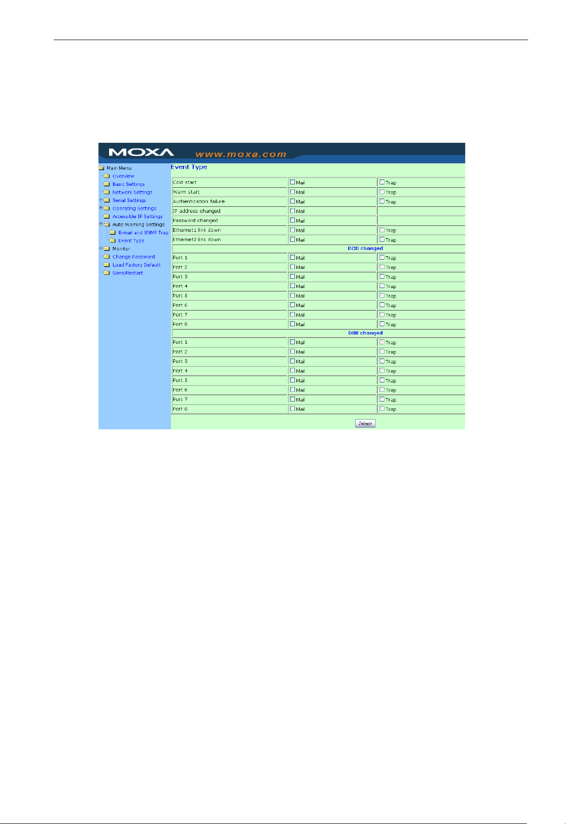
NPort 5600-8-DT/DTL Series General Settin gs
4-8
www.ipc2u.ru
www.moxa.pro
SNMP trap server (default = blank): This optional field is for the IP addre ss or domain name of your SNMP
trap server, if applicable. The SNMP trap server is required for the NPort to send SNMP traps for certain
administrative events.
Event Type
The Event Type parameters are used to configure which events w i ll g e ner ate an automati c warning fr om the
NPort device server, and how that warning will be issued. For each listed event, certain automatic w arning
options are available. If Mail is selecte d, an e-mail will be sent. If Trap is selected, an SNMP trap will be sent.
Cold start: The NPort has booted up after being powered off.
Warm start: The NPort has reboote d w itho ut turning the power off.
Authentication failure: The user has entered the wrong password when trying to access the NPort
configuration parameters from NPor t Adm inis trator or one of the consoles (e.g., web console).
IP address changed: The user has changed the NPort’s IP address. Please note that for this event, the NPort
will reboot with the new IP address without sending an automatic warning e-mail if the NPort is unable to reach
the mail server within 15 seconds.
Password changed: The user has changed NPort’s password. Please note that for this event, the N Por t will
reboot with the new password without sending an automatic warning e-mail if the NPort is unable to reach the
mail server within 15 seconds.
Ethernet1, Ethernet 2 link down: The Ethernet connection is down or the Ethernet cable has been
disconnected.
DCD changed, Ports 1 through 8: The device port’s DCD (Data Carrier Detect) signal has changed, or the
modem connection status has changed. For example, a DCD change to high indicates that the attached modem
has established a valid connection to another modem. A DCD change to low indicates that the connection line
is down.
Page 39

NPort 5600-8-DT/DTL Series General Settin gs
4-9
ATTENTION
DCD and DSR signal changes are
ATTENTION
If you forget the NPort’s password, the ONLY way to configure the NPort is by using the hardware reset button
load the factory defaults.
Before you set a password for the first time, it is a good idea to export the NPort’s completed configuration to
a file. Your configuration can then be easily restored if necessary. For additional information on configuration
management, please refer to Chapter 8.
www.ipc2u.ru
www.moxa.pro
DSR changed, Ports 1 through 8: The device port’s DSR (Data Set Ready) signal has changed, or the
attached device has no power. For example, a DSR change to high indicates that the DCE (Data Communication
Equipment) is powered on. A DSR change to low indicates that the DCE is power e d off.
only applicable for the RS-232 interface.
Change Password
You can set a password to restrict access to the NPort’s configuration parameters. If a user does not enter the
password, access to the NPort configuration settings will be denied, whether it is through NPort Administrator
or through one of the consoles (e.g., web console). In order to remov e passwo rd prote c tion, le ave the New
password and Retype passwor d parameters blank.
Page 40

5
www.ipc2u.ru
www.moxa.pro
5. Introduction to Operation Modes
In this chapter, we describe the various device port operation modes available on NPort 5600-8-DT/DTL device
servers. The operation mode determines how the devic e port wi ll inte ract with the network. The selection of
operation mode will depend on your specific app li c ation. After choosing the proper operation mode in this
chapter, please refer to Chapter 6 for information on configuring the operation mode advanced settings.
The following topics are covered in this chapter:
Overview
Real COM Mode
RFC2217 Mode
TCP Server Mode
TCP Client Mode
UDP Mode
Pair Connection Modes
Reverse Telnet Mode
Disabled Mode
Page 41

NPort 5600-8-DT/DTL Series Introduction to Ope r ation Modes
5-2
Real COM mode is designed to work with NPort drivers that are installed
on a network host. COM drivers are provided for Windows systems , and
TTY drivers are provided for Linux systems. The driver establishes a
transparent connection to the attached s eria l device by mapping a local
serial port to the device port’s IP:Port. Real COM mode supports up to
four simultaneous connections, so multiple
the attached device at the same time.
ATTENTION
Real COM drivers are installed automatica lly with NPort Administrator.
www.ipc2u.ru
www.moxa.pro
Overview
The NPort 5600-8-DT/DTL connects RS-232/422/485 devices to an Ethernet network. In a typical application,
a traditional SCADA and data collection sy s te m relies on serial de vices to collect data from various kinds of
instruments. With the NPort device server, the SCADA and data collection system can access instrument data
over a standard TCP/IP network, whether the devices ar e used locall y or at a remo te site.
Each device port on the NPort 5600-8-DT/DTL is configured inde pe nd e ntly of the other device ports, with its
own serial communication parameters and operation mode. A device port’s operation mode determines how it
interacts with the network, and different modes are available to encompass a wide variety of applications and
devices.
Real COM and RFC2217 modes allow serial-based software to access the device port as if it were a local serial
port on a PC. These modes are appropriate when your application relies on Windows or Linux software that was
originally designed for locally attached COM or TTY devices. With these modes, you can access your devices
from the network using your existing COM/TTY-base d software, without investing in additional software.
Three different socket modes are availabl e for user-developed soc ket program s: TCP Server, TCP Client, and
UDP Server/Client. For TCP applica tio ns , the appr opriate mode depends on whether the connection will be
hosted or initiated from the device port or from the network . The main diff er e nc e betwe en the TC P and UDP
protocols is that TCP guarantees delivery of data by requiring the recipient to send an acknowledgement to the
sender. UDP does not require this type of verification, making it possible to offer speedier delivery . UDP a lso
allows multicasting of data to groups of IP addresses and would be suitable for streaming media or non-critical
messaging applications such as LED message boards.
Pair Connection Slave and Master modes are designed for serial-to-serial communication over Ethernet, in
order to overcome traditional limitatio ns w ith s eria l tr a ns mission distance.
Reverse Telnet mode is designed for conne c tio ns to server s that will ho s t term inal s e ssions through the
device port. This mode is typically used for console management applications, but can also be used to upgrade
legacy servers to network operation.
Real COM Mode
hosts can collect data from
Real COM mode allows you to continue using your serial communicatio ns software to access devices that are
now attached to your NPort device server. On the host, the NPort Real COM driver automatically intercepts data
sent to the COM port, packs it into a TCP/IP packet, and redirects it to the networ k. At the other end of the
connection, the NPort device server accep ts the Ethe r ne t frame, unpack s the TCP/IP packet, and sends the
serial data to the appropriate device.
Page 42

NPort 5600-8-DT/DTL Series Introduction to Ope r ation Modes
5-3
ATTENTION
In Real COM mode, several hosts can have simultaneous access control over the device port. If necessary, you
can limit access by using the Accessible IP settings. Please refer to Chapter 4 for additional information about
Accessible IP settings.
In TCP Server mode, the device port is assigned an IP:Port
address that is unique on your TCP/IP network. It waits for the
host computer to establish a connection to the attache d ser ial
device. This operation mode also suppor ts up to four
simultaneous connections, so multiple ho s ts can colle c t d ata
from the attached device at the same time.
Data transmission proceeds as follows:
A host requests a connecti
Once the connection is established, data can be transmitted in
both directions
device to the host.
In TCP Client mode, the NPort actively establishes a TCP
connection to a
from the attached serial device. After the data has been
transferred, the NPort can automatically d isconnect from the
host computer through the Inactivity time setting s . Ple as e
refer to Chapter 6 for details on t
Data transmission proceeds as follows:
The NPort requests a connection from the host.
The connection is established and data can be transmitte d in
both directions between the host and device .
www.ipc2u.ru
www.moxa.pro
RFC2217 Mode
RFC-2217 mode is similar to Real COM mode, since it relies on a driver to transparently map the device port to
a virtual COM port on a host computer. The RFC2217 standard defines general COM port control options based
on the Telnet protocol and supports one connectio n at a time. Third party drivers supporting RFC-2217 are
widely available on the Internet and can be used to implement virtual COM mapping.
TCP Server Mode
on to the device port.
—from the host to the device, and from the
TCP Client Mode
specific network host when data is received
hese parameters.
Page 43

NPort 5600-8-DT/DTL Series Introduction to Ope r ation Modes
5-4
UDP is similar to TCP but is faster and more efficient. Data can
be broadcast to or received from multiple network hos ts .
However, UDP does not support verification of data and would
not be suitable for applications where data inte gr ity is critical.
It is ideal for message display applicati
Pair Connection Master and Slave modes connect two NPor t
device servers over Ethernet for serial
communication. The two NPort device servers can conne c t to
each other with a Ethernet cable, connect to the same LAN, or
in a more advanced setup, communicate to each other over a
WAN (i.e., through one or more routers). A device attached to
one NPort can then communicate transparently to a device
attached to the other NPort, as if the two devices were
connected by a seri
signals are exchanged, except for DCD signals . This can be
used to overcome traditional limitations w ith s e rial
communication distance and introduces many new possibilities
for serial
In Reverse Telnet mode, the device port is connected to a
server and waits for a terminal session to from a host on the
network. This is an appropriate mode for console management,
with device ports connected to the console/AUX or COM ports
of r
Reverse Telnet mode assists with CR/LF convers ion.
www.ipc2u.ru
www.moxa.pro
UDP Mode
ons.
Pair Connection Modes
-to-serial
al cable. Both data and modem control
-based device control.
Reverse Telnet Mode
outers, switches, or UPS units. Unlike TCP Server mode ,
Disabled Mode
A device port can be disabled by selecting the Disabled operation mode.
Page 44

6
www.ipc2u.ru
www.moxa.pro
6. Operation Mode Advanced Settings
Each device port on NPort 5600-8-DT/DTL device servers operate in one of the available operation modes, such
as Real COM mode or Reverse Telnet mode. For each ope ration mode, different parameters can be configured.
This chapter explains the settings for ev ery par ame ter for eve ry oper ati o n mode.
The following topics are covered in this chapter:
Overview
List of Parameters
When to Make Adjustments
Using Pair Connection Modes
Parameter Details
Connection Management Parameters
Data Packing Parameters
Other Parameters
Page 45

NPort 5600-8-DT/DTL Series Operation Mode Adv a nced Settings
6-2
Real COM Mode TCP Server Mode TCP Client Mo de UDP Mode Reverse Tel n e t Mode Pair Connection Mode RFC2217 Mod e
Delimiter 1 and 2
www.ipc2u.ru
www.moxa.pro
Overview
The device port operation mode determines how the port interacts with the network. Depending on your
application and device, more than one opera ting mode may be suitable. Whe n setting the op er ation mode,
different parameters may be adjusted depend ing o n the operation mode.
For each mode, the default settings should work for most applications. Modify these settings only if absolutely
necessary for your application. The oper ation mode and related parameters can be configured through NPor t
Administrator. The sa me paramete r s may als o be config ur ed usi ng the web console, Telnet console, or serial
console.
List of Parameters
Connection Management Parameters
Data Packing Parameters
Other Parameters
Allow driver control
Command port
Max connection
Ignore jammed IP
De s ti nation IP address 1 through 4
Designated local port 1 through 4
Lo c al lis te n port
Connection Control
TCP alive check time
Inactivity time
Packing length
Delimiter process
Force transmit
Loc al TC P port
Destination IP address
Map <CR-LF>
When to Make Adjustments
The default settings for each operation mode are designe d to work for most applic a tio ns , and usually do not
need to be modified. However, adjustments may be req uired for the following situations:
• You need to control network data packing using specif ic de limiter characters. Adjust Delimiters 1 and 2
and Delimiter proce ss.
• Multiple hosts will simultaneously access the attached device. Adjust Max Connection, Ignore Jammed
IP, and Allow driver control.
• Data will be broadcast from the serial device to multiple networ k destina tio ns . Adjust Destination IP 1
through 4.
Page 46

NPort 5600-8-DT/DTL Series Operation Mode Adv a nced Settings
6-3
Real COM Mode
TCP Server Mode
TCP Client Mode
Reverse Telnet Mode
Pair Connection Mode
RFC2217 Mode
host does not respond to “TCP alive check” packets. If the host does not
Real COM Mode
TCP Server Mode
TCP Client Mode
Reverse Telnet Mode
Pair Connection Mode
RFC2217 Mode
www.ipc2u.ru
www.moxa.pro
• You are using Pair Connection modes to connect two serial devices over Ethernet. Adjust Local TCP port
and Destination IP Address.
Using Pair Connection Modes
For some applications, you may simply want a serial device to communicate directly to another serial device
over the network. You can use a pair of NPort 5600-8-DT/DTL device servers to accomp lish this, w i th Pair
Connection Master and Slave modes. Simply set one device port to Pair Connection Master mode and the other
device port to Pair Connection Slave mode. It does not matter which device port is master and which is slave.
For the device port in Pair Connection Slave mode, designate a Local TCP port to be used for communication.
For the device port in Pair Connection Master mode, enter the s la ve’ s I P addres s and Loca l TCP port as the
Destination IP.
Once both device ports have been configured, the attached serial devices will communicate over Ethernet as if
they were connected b y a seri al cabl e. The t wo device ser vers can be conn ected by an Eth ernet cable, o r th ey
can be connected to the same network.
Parameter Detail s
Connection Management Parameters
UDP Mode
UDP Mode
Inactivity time
TCP alive check time
Range: 0 to 99 minutes
Default: 7 minutes
Description: This is the time limit for keepi ng the connec tion o pen if a
respond within the specified time, the connection will be closed. A setting
of 0 means that the connection will remain open even if the host never
responds.
Range: 0 to 65535 ms
Default: 0
Description: This specifies the time limit for keeping the connection open
if no data flows to or from the serial device. If there is no activity for the
specified time, the connection will be clos e d . A setting of 0 means that
the connection will remain open even if data is never received.
For many applications, the serial device may be idle for long per iod s of
time, so 0 is an appropriate setting. If you wish to use Inactivity time with
TCP Client mode, you must set Connection Contro l is to Any
Character/Inactivity Time (see Connec tion Control).
When adjusting Inactivity time, make s ure that it is gre a ter than the
Force transmit time. Otherwise, the TCP connection may be closed before
data in the buffer can be transmitted.
Page 47

NPort 5600-8-DT/DTL Series Operation Mode Adv a nced Settings
6-4
Real COM Mode
TCP Server Mode
TCP Client Mode
Reverse Telnet Mode
Pair Connection Mode
RFC2217 Mode
Real COM Mode
TCP Server Mode
TCP Client Mode
UDP Mode
Reverse Telnet Mode
Pair Connection Mode
RFC2217 Mode
responsive. “No” means
Real COM Mode
TCP Server Mode
TCP Client Mode
Reverse Telnet Mode
Pair Connection Mode
RFC2217 Mode
Real COM Mode
TCP Server Mode
TCP Client Mode
UDP Mode
Reverse Telnet Mode
Pair Connection Mode
RFC2217 Mode
www.ipc2u.ru
www.moxa.pro
Max connection
Range: 1 to 4
Default: 1
Description: This specifies the maxim um number of sim ultane ous
UDP Mode
Ignore jammed IP
Allow driver control
UDP Mode
connections that the port will accept. When adjus ti ng Max connec tio n,
make sure that Ignore jammed IP and Allow driver control are also
adjusted correctly.
Range: Yes or No
Default: No
Description: This field specif i es how an unre spo ns ive IP addres s is
handled when there are simultaneous connections to the device port (see
Max connection). “Yes” means that transmiss ion to the other hosts will
not be suspended if one IP address becomes un
that all transmission will be suspended if one IP address b ecomes
unresponsive, and will resume when all hosts have respo nded. “Yes” is
the recommended setting when Max connectio n is 2 or more.
Range: Yes or No
Default: No
Description: This specifies whether the device port will respond to driver
control commands when multiple simultaneous connections are enabled
(see Max connection).
Data Packing Parameters
Packing length
Range: 0 to 1024
Default: 0
Description: This controls data packing by the amount of data receiv ed .
Serial data accumulates in the device por t’ s buffer until it r eache s the
specified length. When the specified amount of data has accumulated in
the buffer, the data is packed for network transmiss ion. A setting of 0
means that data will not be packed until the buffer is full. 0 is the
recommended setting, unless your application has a specific need to limit
packet sizes or improve response times.
Page 48

NPort 5600-8-DT/DTL Series Operation Mode Adv a nced Settings
6-5
Real COM Mode
TCP Server Mode
TCP Client Mode
Reverse Telnet Mode
Pair Connection Mode
RFC2217 Mode
ATTENTION
When the device port buffer is full, the data will be packed for network transmission, regardless of the settings
for Delimiter 1, Delimiter 2, and Force transmit.
Real COM Mode
TCP Server Mode
TCP Client Mode
UDP Mode
Reverse Telnet Mode
Pair Connection Mode
RFC2217 Mode
Real COM Mode
TCP Server Mode
TCP Client Mode
Reverse Telnet Mode
Pair Connection Mode
RFC2217 Mode
www.ipc2u.ru
www.moxa.pro
UDP Mode
Delimiter 1 and 2
Range: 0 to FF, Enable
Default: Disabled
Description: This controls data packing by special delimiter character(s).
Serial data accumulates in the device port’s buffer until the delimiter
character(s) are received, after which the data is pack ed for ne two rk
transmission. If only one delimiter character is needed, be sure to enable
Delimiter 1 only. If both Delimiter 1 and 2 are enabled, both characters
must be received in sequence for data packing to occur. For example, the
carriage return character could be used as a delimiter in order to transmit
each sentence or paragraph in a separate packet. Data is packed
according to the Delimiter process parameter.
Delimiters must be incorporated into the d ata stream at the software or
device level.
Delimiter process
Range: Do Nothing, Delimiter + 1, Delimiter + 2, Strip
Delimiter
Default: Do Nothing
Description: This controls how data is pa cked when de limite r characters
are received. Note that this field has no effec t if delimite rs are not
enabled (see Delimiters 1 and 2).
”Do nothing” will pack the accumulated data includ ing delimiters.
”Delimiter + 1” will wait for an additional charac te r befo re pac k ing the
accumulated data.
”Delimiter + 2” will wait for two additional characters before packing the
accumulated data.
”Strip Delimiter” will pack the accumulated data but will not include the
delimiter characters in the packet.
UDP Mode
Force transmit
Range: 0 to 65535 ms
Default: 0 ms
Description: This controls data packing by the amount of time that
elapses between bits of data. As serial data is received, it accumulates in
the device port’s buffer. If serial data is no t receive d for the specified
amount of time, the data that is currently in the buffer is packed for
network transmission. A setting of 0 means that data in the buffer will not
be automatically packed when no further data is rece ived from the
device. When using this field, make sure that Inactivity time is disabled or
set to a larger value. Otherwise the connection may be closed before the
data in the buffer can be transmitted.
Page 49

NPort 5600-8-DT/DTL Series Operation Mode Adv a nced Settings
6-6
Real COM Mode
TCP Server Mode
TCP Client Mode
UDP Mode
Reverse Telnet Mode
Pair Connection Mode
RFC2217 Mode
Real COM Mode
TCP Server Mode
TCP Client Mode
Reverse Telnet Mode
Pair Connection Mode
RFC2217 Mode
Real COM Mode
TCP Server Mode
TCP Client Mode
Reverse Telnet Mode
Pair Connection Mode
RFC2217 Mode
Real COM Mode
TCP Server Mode
TCP Client Mode
Reverse Telnet Mode
Pair Connection Mode
RFC2217 Mode
Real COM Mode
TCP Server Mode
TCP Client Mode
Reverse Telnet Mode
Pair Connection Mode
RFC2217 Mode
www.ipc2u.ru
www.moxa.pro
Other Parameters
Command port
UDP Mode
UDP Mode
Local TCP port
Range: 1 to 65535
Default: 4001 for port 1, 4002 for port 2, etc.
Description: This specifies the TCP port number for communication to the
attached device. Socket applications will need to refer to the device using
this port number. For Pair Connection modes, this f ie ld spe c ifies the
slave’s port number, and the same value must be used for the master’s
Destination IP parameter.
Range: 1 to 65535
Default: 966
Description: This specifies the TCP port number for Moxa IP-Serial Library
commands. You do not need to reference this port number in your
application when using the Moxa IP-Serial Lib r ary, since the library
automatically obtains the number fr om the devic e ser ver. Change this
setting only if there is a port number conflict with another application or
device.
Destination IP address
Range: N/A
Default: none
Description: This specifies the IP addres s for the slav e end of a pair
connection.
Destination IP address 1 through 4
Range: N/A
Default: none
Description: This specifies the networ k host(s ) that w il l ac c ess the
UDP Mode
Designated local port 1 through 4
UDP Mode
device. Serial data will be transmitted to eve ry addre ss lis ted , and
network data will be sent to the device on a first-in-first-out basi s .
Range: 1 to 65535
Default: none
Description: This specifies the TCP port number that will be used for data
transmission with the device port.
Page 50

NPort 5600-8-DT/DTL Series Operation Mode Adv a nced Settings
6-7
Real COM Mode
TCP Server Mode
TCP Client Mode
Reverse Telnet Mode
Pair Connection Mode
RFC2217 Mode
Real COM Mode
TCP Server Mode
TCP Client Mode
Reverse Telnet Mode
Pair Connection Mode
RFC2217 Mod e
and the connection can only be
Real COM Mode TCP Server Mode TCP Client Mo de UDP Mode Reverse Tel n e t Mode Pair Connection Mode RFC2217 Mod e
www.ipc2u.ru
www.moxa.pro
Local listen port
Range: 1 to 65535
Default: 4001 for port 1, 4002 for port 2, etc.
Description: This specifies the UDP port number for ne twork
UDP Mode
Connection Control
UDP Mode
Map <CR-LF>
communication to the serial device. Socket applications will need to refer
to the device using this port number.
Range: Startup/None, Any Character/None, Any Character/Inactivity
Time, DSR On/DSR Off, DSR On/None, DCD On/DCD Off, DCD On/None
Default: Startup/None
Description: This specifies how connections to the device are established
and closed.
For example, “Startup/None” means that as soon as the device serv er
starts up, the TCP connection is opened,
closed manually. “DCD On/DCD Off” means that the TCP connection is
opened when the DCD signal is on, and closed when the DCD signal is off.
If you want to use the Inactivity Time parameter to close the connection
when the serial device is inactive, you must set Connection Control to
“Any Character/Inactivity time” .
Range: CR, LF, or CR-LF
Default: CR-LF
Description: This specifies how the ENT ER key is mapped from the
Ethernet port through the serial port. For cer tain term inal a p p l ic ations,
the Enter key needs to be translated specifically as a CR character rather
than CR-LF.
Page 51

7
www.ipc2u.ru
www.moxa.pro
7. Using the Web Console
The NPort 5600-8-DT/DTL web console allows it to be managed from anywhere on the netw or k using a
standard web browser. This chapter explains ho w to us e the web co nsol e .
The following topics are covered in this chapter:
Overview
Web Browser Settings
Basic Navigation
Device Server Settings
Special Functions
Monitor
Load Factory Defaults
Page 52
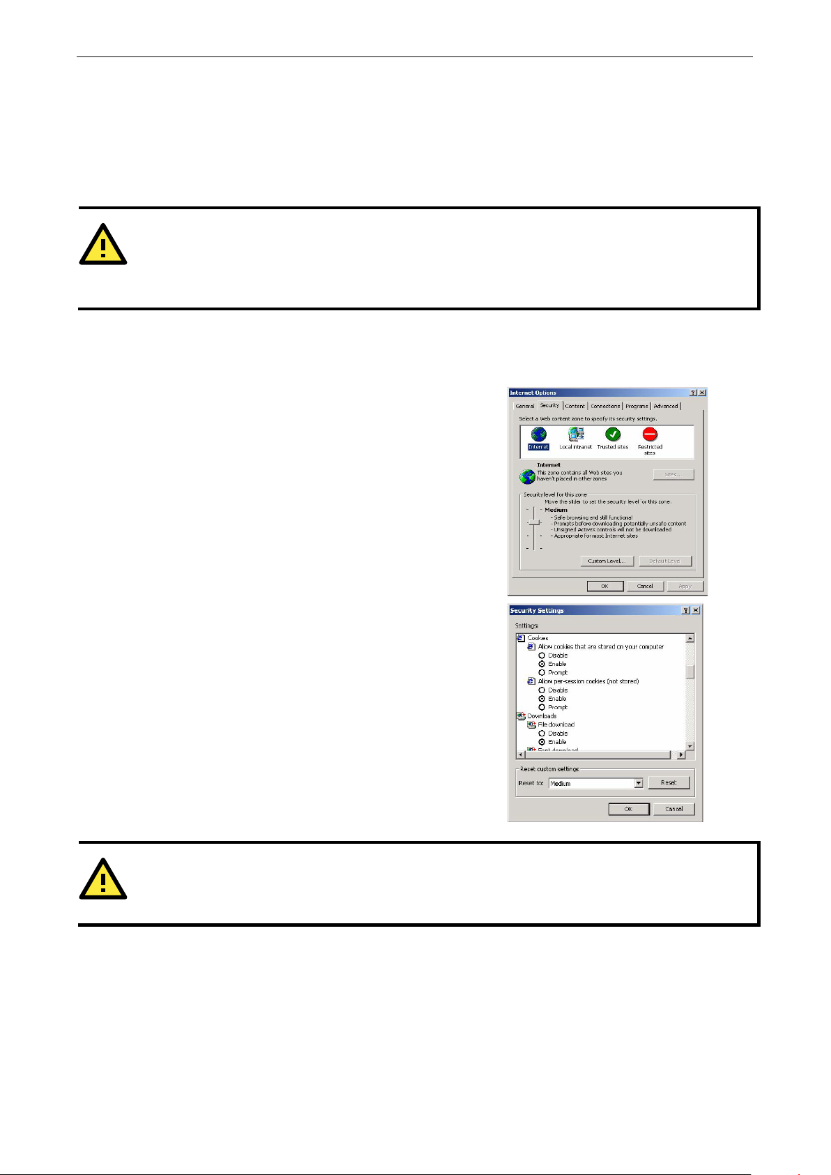
NPort 5600-8-DT/DTL Series Using the Web Consol e
7-2
ATTENTION
All device server settings can be accessed using the web conso l e . Howev e r , certain functions such as p
monitoring or configuration export are only available through NPort Administrator. Please refer to Chapter 8 for
more details on using NPort Administrator.
In order to use the web console, you will need to have cookies
enabled for your browser. Please note that the web console uses
cookies only for password transmission. For Inte rnet Explorer,
cookies can be enabled by right
icon on your desktop and selecting Properties from the conte x t
menu.
On the Security tab, click “Custom Level…” and enable these two
items:
Allow cookies that are stored on your computer
Allow per
ATTENTION
If you are not using Internet Explorer, cookies are
“allow cookies that are stored on your computer” or “allow per
www.ipc2u.ru
www.moxa.pro
Overview
The NPort can be configured from anywhere on the network through its web console. Simply point the browser
to the device server’s IP address to open the web console. Network settings, operation mode, and other items
can all be modified through the browser. This is a handy option for configuration if you cannot or do not wish
to install NPort Administrator .
Web Browser Settin g s
-clicking the Internet Explorer
-session cookies (not stored)
ort
usually enabled through a web browser setting suc h as
-session cookies.”
Page 53
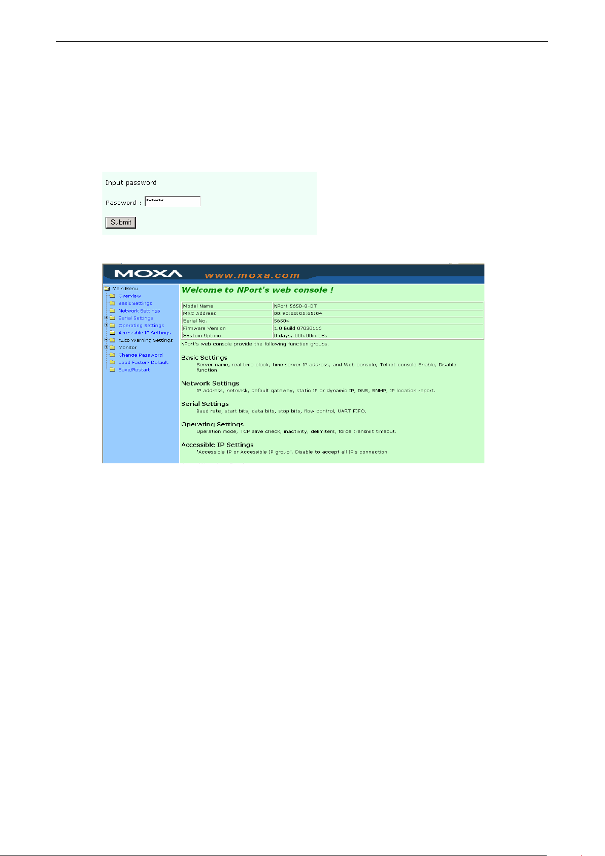
NPort 5600-8-DT/DTL Series Using the Web Consol e
7-3
www.ipc2u.ru
www.moxa.pro
Basic Navigation
To open the web console, enter your device server’s IP addre s s in the website addre s s line. I f you are
configuring the NPort for the first time, you will use the def ault IP addr e s s , 192.168.127.254.
If prompted, enter the console password. You will only be pro mpte d for a passw or d if you have enabl ed
password protection on the device server. The password will b e tr ans mitte d w ith MD5 encryp tion over the
Ethernet.
The web console will appear as shown below.
The left panel is the navigation panel, where you select the parameters that you wish to see or modify. Certain
folders can be expanded by clicking the adjacent “+” symbol.
The right panel is the main window, where parameters are disp layed and modified. For example, if you click
Basic Settings in the navigation panel, the main window will show a page of basic settings that you can
configure.
After you have made changes on a page, you must click the Submit button in the main window before jumping
to another page. Your changes will be lost if you do not click Submit.
After you have finished modifying the desired pages, you must save and restart the device server for the new
settings to take effect. You may complete this in one step by clicking Save/Restart after you submit a change.
Changes will not take effect until they are saved and the NPor t is resta r ted . If you restart the NPort without
saving your configuration, all configuration changes will be lost.
Page 54
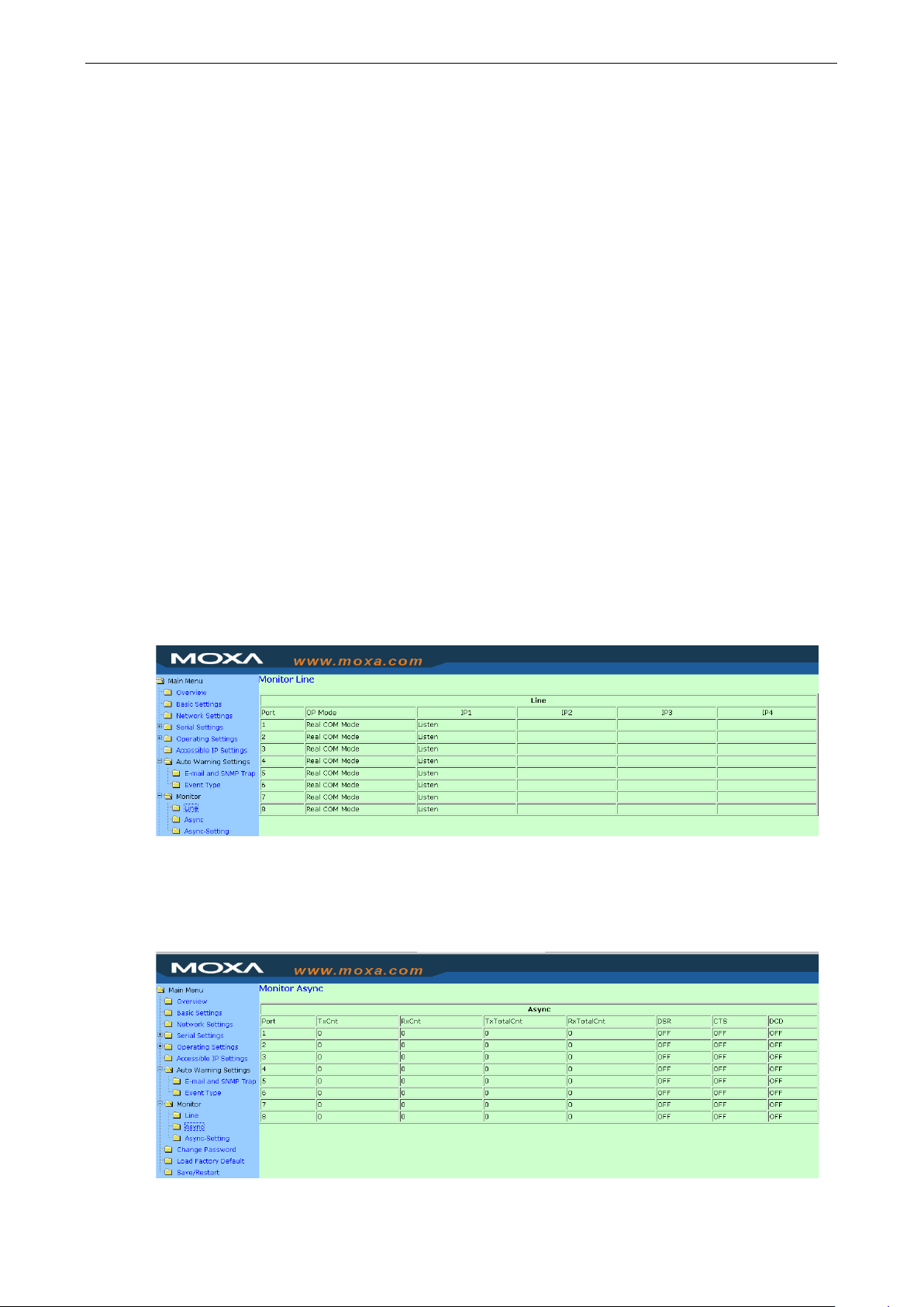
NPort 5600-8-DT/DTL Series Using the Web Consol e
7-4
www.ipc2u.ru
www.moxa.pro
Device Server Settings
Please refer to Chapter 4 for details on the following se tting s:
• Basic Settings
• Network Settings
• Serial Settings
• Accessible IP Settings
• Auto Warning Settings
• Change Password
• For details on Operating Settings, ple ase refer to C hapter 5.
Special Functions
There are several special functions that are available in the web console. These functions are not available on
NPort Administrator.
Monitor
Select one of the Monitor functions in the navigation panel to monitor traffic on the NPort device server. Refresh
your browser to display updated status.
Line
Monitor each device p or t’ s oper ati o n mode and conne c tion status (IPx).
Async
Monitor each device port’s serial signal status.
Page 55

NPort 5600-8-DT/DTL Series Using the Web Consol e
7-5
www.ipc2u.ru
www.moxa.pro
Async-Settings
Monitor each device port’s serial run-time settings.
Load Factory Defaults
This will load the NPort’s factory default conf ig uration. All parameters will be reset, and the curre nt
configuration settings will be lost. It is strongly recommended that you first save your configuration to a file so
that it can be restored if necessary. Please refer to Chap ter 8 for deta ils on impo rting and exporting your
configuration in NPort Administrato r.
Page 56

8
www.ipc2u.ru
www.moxa.pro
8. Using NPort Administrator
The following topics are covered in this chapter:
Overview
Installing NPort Administr ator
Basic Navigation
Window Layout
Activating a Function
Configuration
Finding Your Device Server
Status
Device Serve r Parameters
Firmware and Configuration Management
Monitor
Finding Your Device Server
Monitoring Parameters
Activating the Monitor
Port Monitor
COM Mapping
Finding Your Device Server
COM Mapping Settings
Saving COM Mapping Settings
COM Grouping
Creating a COM Group
Deleting a COM Group
Adding a Port to a COM Group
Removing a Port from a COM Group
Modifying Ports in a COM Group
IP Address Report
Automatic Message Log
Page 57
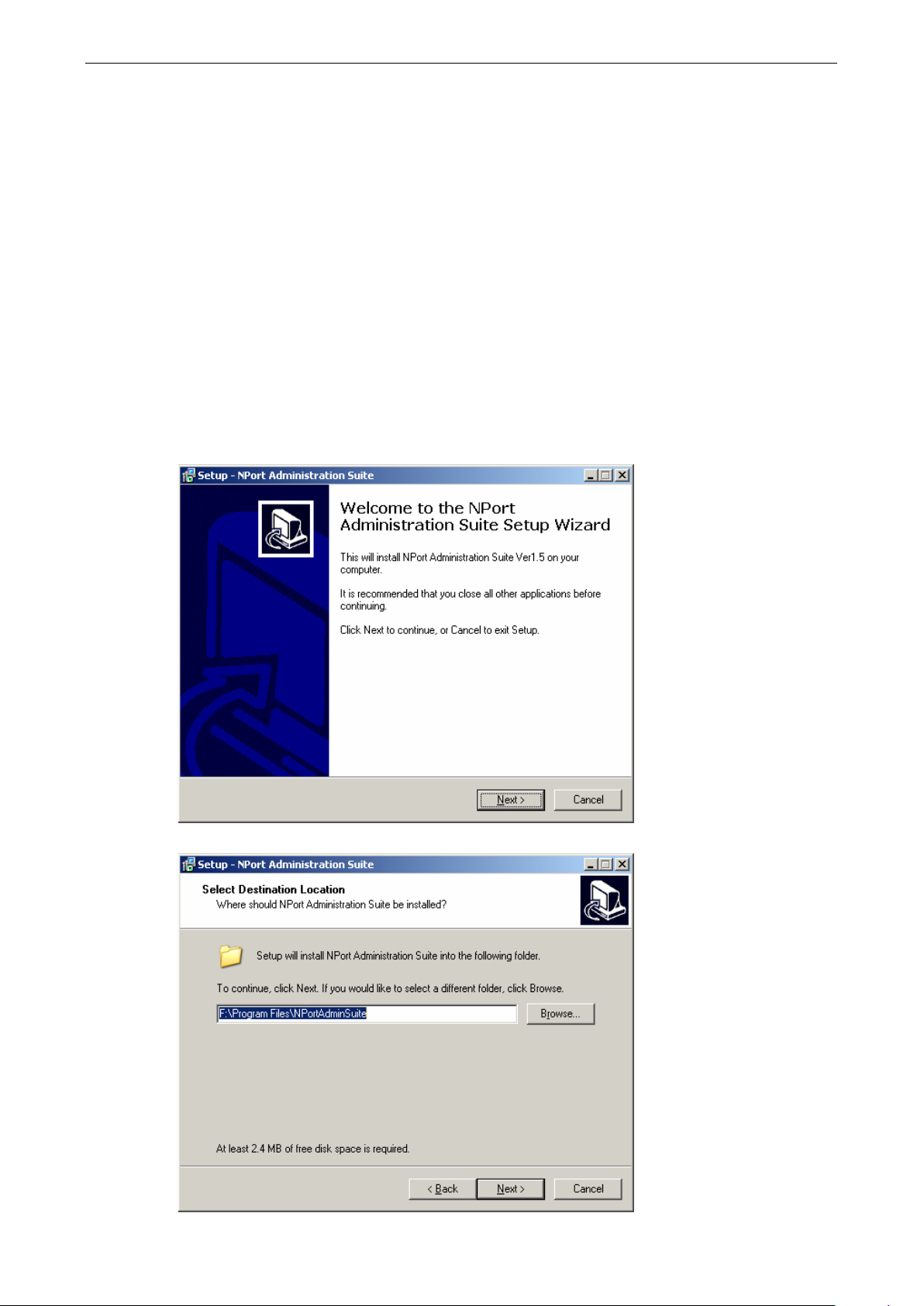
NPort 5600-8-DT/DTL Series Using NPort Administrator
8-2
www.ipc2u.ru
www.moxa.pro
Overview
The NPort Administration Suite provides everything you need to manage, monitor, and modify your NPort from
a remote location. It includes NPort Adminis trator and the IP Serial Library.
With NPort Administrator, you can easily install and configure your NPort device server over the network. You
can also run NPort Administrator from one loc ation to manage multiple device servers.
Installing NPort Administrator
NPort Administrator can be installed from the Document and Software CD onto a Windows PC. To install NPort
Administration Suite, insert the NPort Document & Software CD into your PC’s CD-ROM drive. Locate and run
the setup program and follow the on-screen instructio ns . The se tup prog ram will be named
Npadm_Setup_[Version]_Build_[DateTime].exe (e.g., “Npadm
_Setup_Ver1.8_Build_07041316.exe”).
1. When you run the setup program fro m the Docume nt and Sof tware CD, a Welcome window will appear.
Click Next to proceed.
2. Click Next to accept the proposed installation directory, or click Browse… to select an alternative location.
Page 58

NPort 5600-8-DT/DTL Series Using NPort Administrator
8-3
www.ipc2u.ru
www.moxa.pro
3. Click Next to accept the proposed Start menu folder, or se lect a diffe re nt fo ld er .
4. Click Install to proceed with the installation.
5. The setup wizard will sho w the progre s s of the installation.
Page 59

NPort 5600-8-DT/DTL Series Using NPort Administrator
8-4
www.ipc2u.ru
www.moxa.pro
6. A special notice will ap p e ar. Click Next after reading the notice.
7. Click Finish to complete the installation of the NPort Adm inis tration Suite.
Page 60

NPort 5600-8-DT/DTL Series Using NPort Administrator
8-5
www.ipc2u.ru
www.moxa.pro
Basic Navigation
Window Layout
NPort Administrator is designed to make it easy to configure, monitor, or manage any NPort 5600-8-DT/DTL on
your network. The interface is organize d into fo ur areas as follo w s :
• The top section is the menu area.
• The left panel is the Function panel. This is where you navigate between different functions. You may also
use the Function menu on the menu bar.
• The right panel is the list of device servers that are available for the selected function. A target device server
must be selected from this list in order to activate spe c ific com mands. First right-click the target unit to
bring up a function context menu, then select the desir ed command fro m the menu.
• The bottom section is the log area, which shows a record of status and proces s ing message s .
Activating a Function
All functions in NPort Administrator are activated by first selecting the function, then selecting the target device
server, and finally selecting the specific command:
1. Select the desir ed function in the Function panel.
2. If your device server is already listed in the right panel, you may skip to the next step. If the list of device
servers is empty, you will need to “find” your device server. Right-click the desired function in the function
panel to open the function context menu. You will need to add devic e servers to the list by selecting a
command such as “Search” or “Add Target”.
Page 61

NPort 5600-8-DT/DTL Series Using NPort Administrator
8-6
www.ipc2u.ru
www.moxa.pro
3. Once your device server is on the list for the desired function, right-click the targ e t devic e server to open
the function context menu. Activate the desired command from this context menu. You may also select the
target device server and then open the function context menu from the menu bar.
Configuration
Select the Configuration function to conf ig ure yo ur NPor t, impor t and exp or t its co nfiguration, or update its
firmware.
Finding Your Device Server
If the list of available servers is empty, find your device server on the network using the Broadcast Search or
Specify by IP Address commands in the function contex t menu.
Broadcast Search: This searches for all NPort units on the LAN. Since this search is based on MAC address,
rather than IP address, it will be able to find units that are not on the same subnet as your PC. You may click
Stop as soon as your device server is found.
Specify by IP Address: This allows you to find your device server manually by enter ing its IP addr e s s .
Page 62

NPort 5600-8-DT/DTL Series Using NPort Administrator
8-7
set up for the unit.
www.ipc2u.ru
www.moxa.pro
Status
The NPort may be password-protected to prevent unauthorized configuration changes. Please refer to Chapter
4 for additional information on password prote c tion. The status will be shown in the list of available device
servers. There are six possible statuses for device servers on the network.
Status Description
Lock The unit was located by broadcast search. It is password-protected, and the
correct password has not been provided during this session.
Unlock The unit was located by broadcast search. Passwor d prote c tion has not been
set up for the unit.
(blank) The unit was located by broadcast search. Password protection has not been
Fixed The unit was manually located by “Search IP” and has no password protection.
Lock Fixed The unit was manually located by “Search IP”. It is password protec te d, and
the current password has not been provided during this session.
Unlock Fixed The unit was manually located by “Search IP”. It was password-protected, but
the correct password has been provided for this session.
If you wish to configure a unit that is Locked or Lock Fixed, you will need to unlock the unit first as described
below:
1. Select the Unlo ck com mand in the functio n conte x t menu for the target device server.
2. Enter the password and click OK.
3. If the correct passwor d is provid e d , you will re ceive an “Unlock ok” message.
Page 63

NPort 5600-8-DT/DTL Series Using NPort Administrator
8-8
www.ipc2u.ru
www.moxa.pro
4. The device server’s status will be updated to “Unlock”.
Device Server Parameters
You can configure any NPort 5600-8-DT/DTL on the LAN using the Assig n IP Addre ss, Configure, orWeb
commands in the function context menu.
Assign IP Address: This allows you to set the target NPort’s IP address quickly, instead of digging through
pages of configuration parameters.
Configure: This opens the target device server’s config uratio n w i ndow.
Parameters are grouped into tabs. Please refer to Chapter 4 for a descrip tion of all general settings for the
NPort 5600-8-DT/DTL. C lic k a Modify checkbox to enable changes to the associated parameter. Click OK to
implement changes.
Page 64

NPort 5600-8-DT/DTL Series Using NPort Administrator
8-9
ATTENTION
You can configure multiple units simultaneously, as long as the units are the same model. Simply hold down the
Ctrl or Shift key when selecting the target device
www.ipc2u.ru
www.moxa.pro
Web: This opens the target device server’s web console. Please refer to Chapter 7 for details on using the web
console.
servers.
Page 65
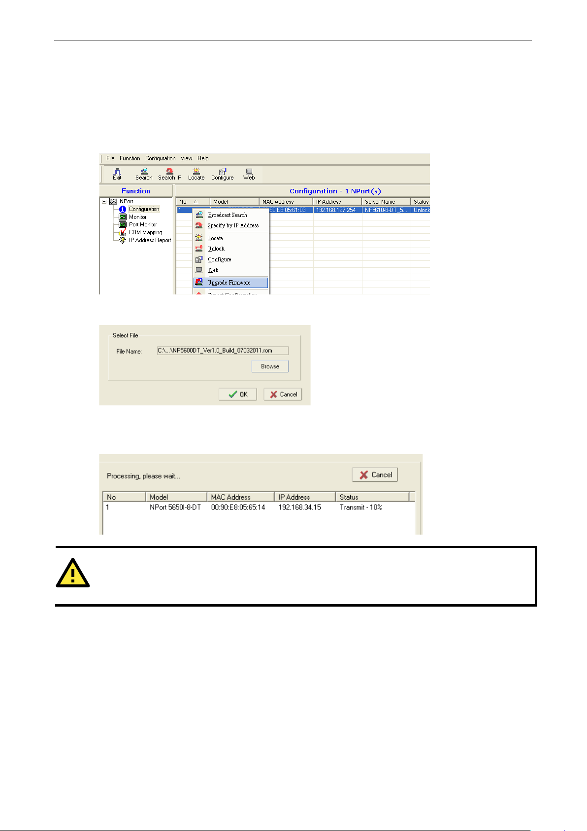
NPort 5600-8-DT/DTL Series Using NPort Administrator
8-10
ATTENTION
You can update the firmware of multiple units simultaneously, as long as the units are the same model. Simply
hold down the Ctrl or Shift key when selecting the targe t devic e serv er s .
www.ipc2u.ru
www.moxa.pro
Firmware and Configuration Management
You can manage your device servers’ firmware and config uration using the Upgra de Firmwar e and
Import/Export Configuration commands.
Upgrade Firmware: This allows you to upload new firmware to the target NPort device server. You can obtain
firmware updates for your NPort 5600-8-DT/DTL at www.moxa.com.
Browse for the new firmware file and click OK.
It will take a few moments for the NPort’s firmware to be updated. Do not disconnect the network, the NPort,
or your PC at any time during the update.
Import/Export Configuration: These commands are used to save or restore the target device server’s
configuration. All config uration se tti ng s c an be stored on a file to be restored late r, from anywhere on the
network.
Page 66

NPort 5600-8-DT/DTL Series Using NPort Administrator
8-11
ATTENTION
You can import the configuration of multiple units si multane ously, as long as the units are the same model.
Simply hold down the Ctrl or Shift key when selecting the targ e t devic e servers.
www.ipc2u.ru
www.moxa.pro
Follow the onscreen instructions to save or restor e the target unit’s c o nfig uration.
Monitor
You can use NPort Administrator for live monitoring of your NPort over the network. Different parameters and
events may be monitored, and you can receive pop-up warnings for certain events.
Finding Your Device Server
If the list of available servers is empty, find your device server on the network using the Add Target or Load
Configured COM Port commands in the function context menu.
Add Target: This selects NPort device servers on the LAN for monitoring. You may need to click “Rescan” to
search the network again for NPort device servers . Once a dev ice serv er has been fo und , sele c t it in order to
add it to the Monitor list. You can also select “Input manually ” to enter a spe c ific IP addr ess a nd mode l for
monitoring.
Remove Target: This removes a device server fr om the monitor li s t.
Load Configured COM Port: If COM ports have been mapped to NPort device servers, this command
automatically adds those device server s to the monitor lis t.
Page 67

NPort 5600-8-DT/DTL Series Using NPort Administrator
8-12
www.ipc2u.ru
www.moxa.pro
Monitoring Parameters
The Settings command specifies which items of information will be monitored, how of te n the information is
refreshed, and how notification of events will o ccur.
In the Monitor Items tab, you may select which items of information will be monitored .
Page 68
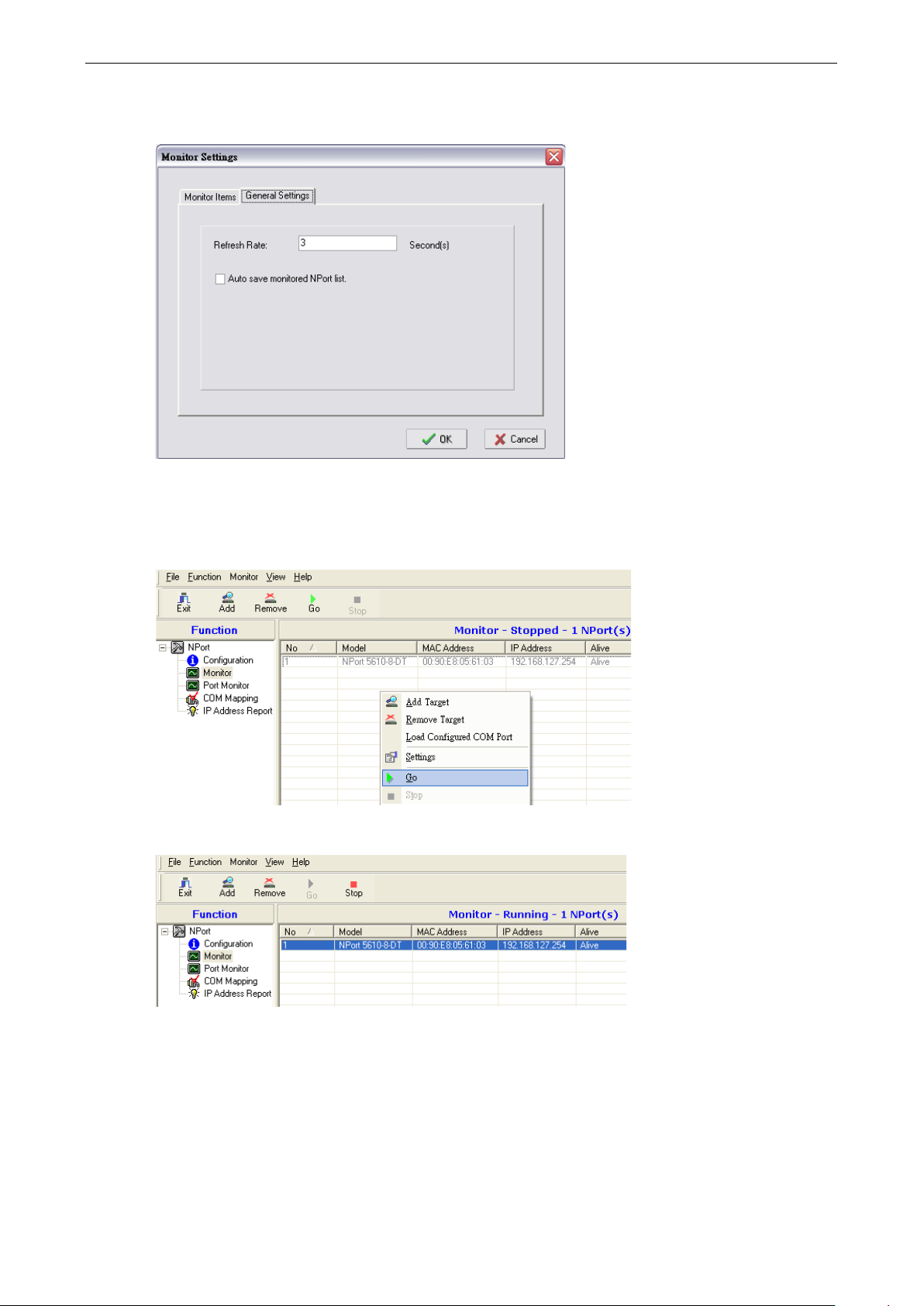
NPort 5600-8-DT/DTL Series Using NPort Administrator
8-13
www.ipc2u.ru
www.moxa.pro
In the General Settings tab, you may select the monitoring refresh rate, which is how often the monitor
function will check the status of each NPort on the monitor lis t. The d ef ault is 3 second s .
Activating the Monitor
The Go command activates live monitoring.
The monitor list will now be monitored live , as indic ate by “Running” in the header.
Page 69
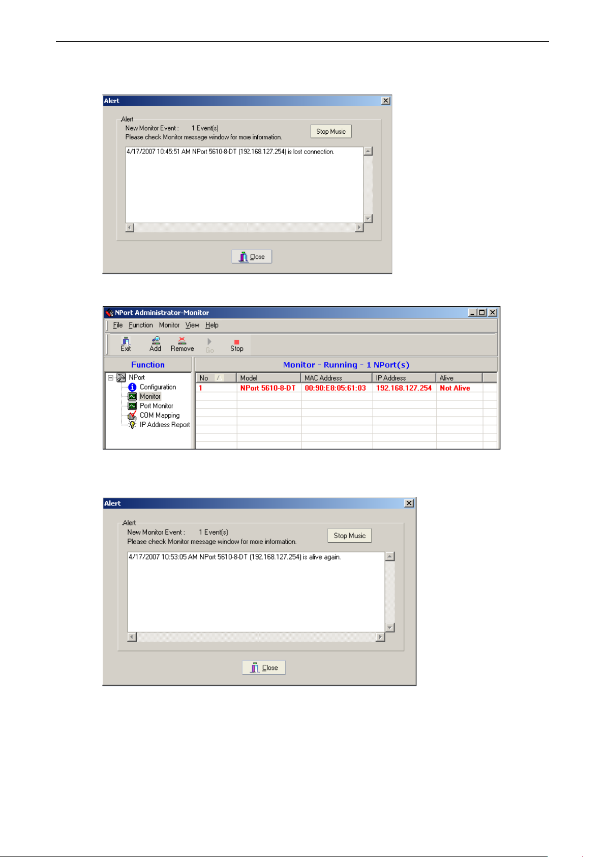
NPort 5600-8-DT/DTL Series Using NPort Administrator
8-14
www.ipc2u.ru
www.moxa.pro
If you configured the monitor function with warnings enabled, a notification will appe ar if a monitore d dev ic e
server goes off-line.
NPorts that are off-line will be also disp l ayed in red in the monitor lis t.
If the NPort is able to re-establish the connection, ano ther notif ic ation will appear indicating that the NPort
5600-8-DT/DTL is now “Alive.” The monitor list will be updated accordingly .
Page 70
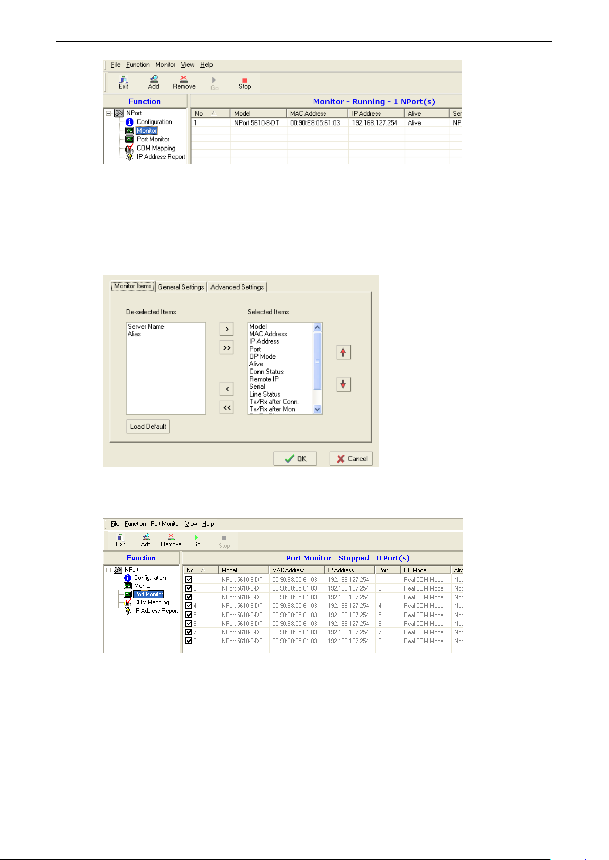
NPort 5600-8-DT/DTL Series Using NPort Administrator
8-15
www.ipc2u.ru
www.moxa.pro
Select the Stop command to suspend live mo nitor ing.
Port Monitor
The Port Monitor function is identical to the Monitor function, but with many additional items that can be
monitored, as shown below.
In addition, each item on the port monitor list will be an individual device port on an NPort device server. Each
device port can be selected or deselected for monitor i ng .
COM Mapping
The NPort Administrator Suite is installed with Real COM drivers that work with Windows 95 and above. These
drivers transparently connect a COM port on the PC to a device port on the NPort device server. This allows a
local application to use COM5, for example, to communicate with a device attached to the NPort. Use the COM
Mapping function to define the mapping assig nme nts .
Page 71
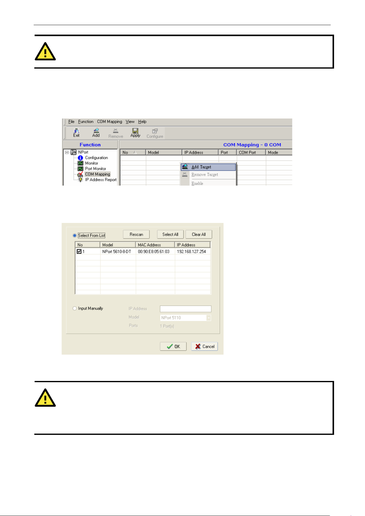
NPort 5600-8-DT/DTL Series Using NPort Administrator
8-16
ATTENTION
A device port must be operating in Real COM mode in order to be used in COM mapping.
ATTENTION
You can configure COM mapping even if your dev
Target command, simply select the “Input manually ” op tion and enter the IP address and model. This is a
useful option for certain field installatio ns w he re COM mapping must be set up before the NPort is physically
installed.
www.ipc2u.ru
www.moxa.pro
Finding Your Device Server
If the list of available servers is empty, find your device server on the network using the Add Target command
in the function context menu.
You may need to click “Rescan ” to sea rch t he netw ork again for NP ort device servers. Once your de vice se rver
has been found, select it in order to add it to the COM mapping list. You can also select “Inp ut manually” to
enter a specific IP address and model.
To remove a device server from the COM mapping list, use the Remove Target command in the function
context menu.
ice server is off-line (not connected). When using the Add
Page 72
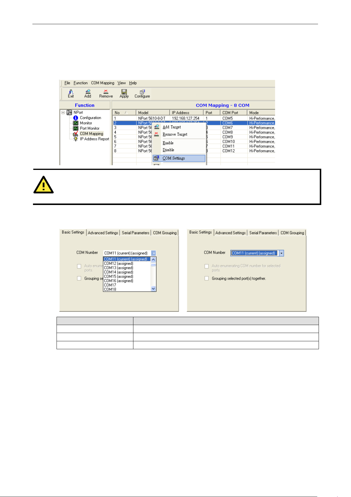
NPort 5600-8-DT/DTL Series Using NPort Administrator
8-17
ATTENTION
You can map multiple COM ports in one step by holding down the Ctrl or Shift key when selecting the targ e t
device ports.
www.ipc2u.ru
www.moxa.pro
COM Mapping Settings
Each item on the COM mapping list refers to an individual device port on an NPort device server. To map a COM
port to a listed device port, right-click the target device port and select COM Settings in the function context
menu.
In the Basic Settings tab, the COM Number parameter selects the COM port that will be mapped to the device
port. The drop-down list shows av aila b le COM ports with status .
Status Description
in use Already being used by system or already mapped to an NPort dev ic e port
assigned Assigned to an NPort device por t but changes have not been app li e d yet
current Assigned to currently selected device port, changes have not been applied yet
The “Auto Enumerating” parameter can be used when mapping multiple device ports at the same time. When
the parameter is checked, this option automatically assigns available COM numbe r s sequentially . If not
checked, you will need to configure COM mapping for each device port separately.
In the Advanced Settings tab, you may configure how serial data is transmitted from the PC to the NPort
device port.
Page 73
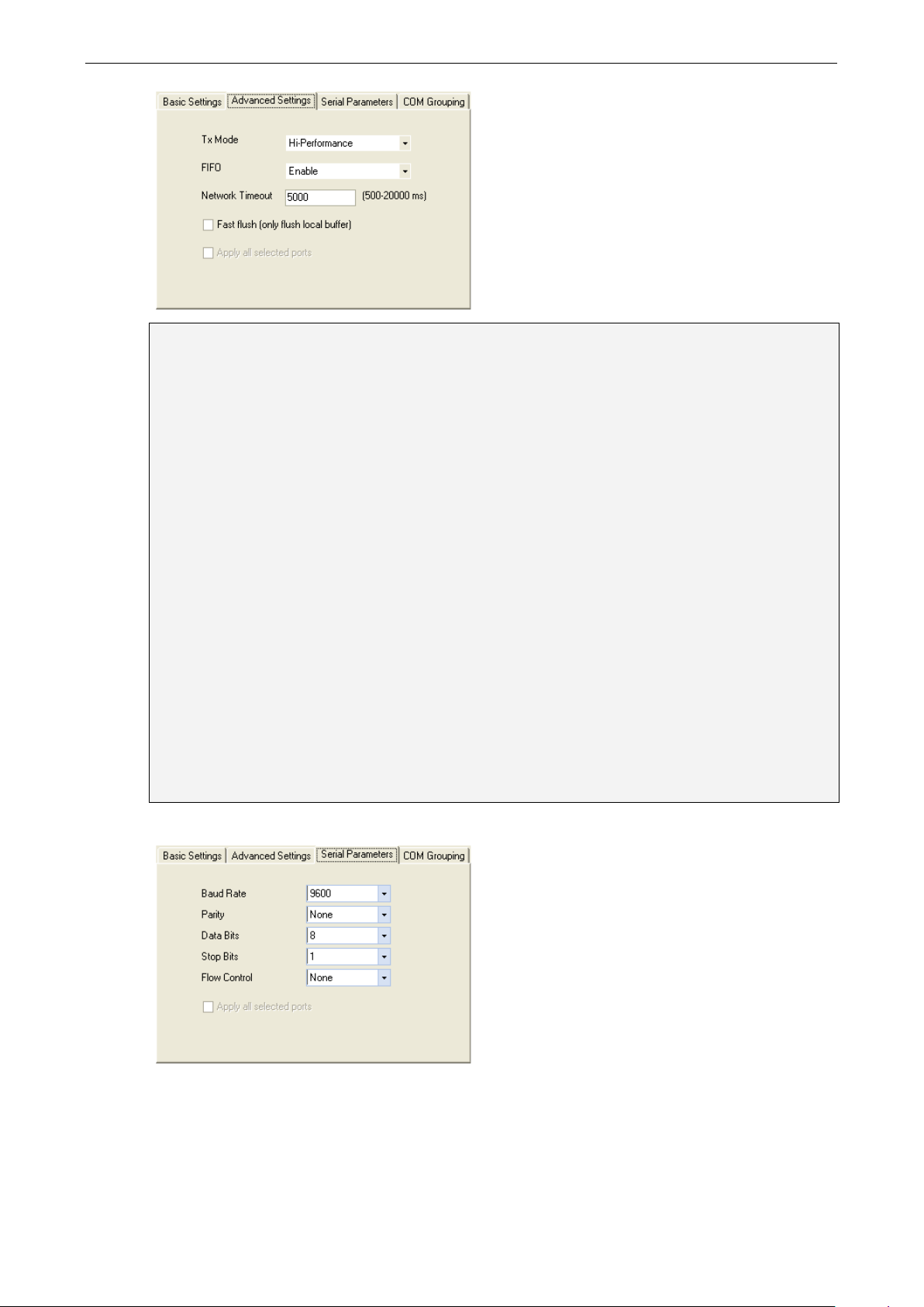
NPort 5600-8-DT/DTL Series Using NPort Administrator
8-18
te each time the Tx FIFO becomes empty, and
www.ipc2u.ru
www.moxa.pro
Tx Mode
Hi-Performance is the default for Tx mode. After the driver sends d ata to the NPort, the dri v er imm ediate ly
issues a “Tx Empty” response to the program. Under Classical mode, the dr iver w ill no t send the “Tx Emp ty”
response until after confirmation is received from the NPort. This causes lower throughput. Classical mode is
recommended if you want to ensure that all data is sent out before f ur ther proc ess ing.
FIFO
When “FIFO” is disabled, the selected device port will send one by
an Rx interrupt will be generated for each incoming byte . This w ill c aus e a faste r response time but lower
throughput.
Network Timeout
“Network Timeout” specifies how long the driver will wait for the attached serial device to respond to an open,
close or serial parameter change operation. If a response is received by the specified time, the operation will
time out. The default value is 5000 milliseconds .
Fast Flush
“Fast Flush” is designed to improve response times for applications that use the Win32 PurgeComm() function.
When Fast Flush is enabled, the Real COM driver only flushes the local buffer on the host when it receives the
PurgeComm() function call. When disabled, applications that use PurgeComm() may perform markedly slower,
because the Real COM driver will need to also flush the remote buffer, which requires repeated queries of the
NPort to make sure no data is queued in the remote buffer. The repeated queries can cause a performance hit
due to the additional time spent communicating over the network, typically about several hundred milliseconds
when compared to COM ports. If your application uses PurgeComm() and performance seems sluggish, try
enabling Fast Flush.
In the Serial Parameters tab, the COM port’s serial communication par am e ters ar e def ined.
Page 74

NPort 5600-8-DT/DTL Series Using NPort Administrator
8-19
www.ipc2u.ru
www.moxa.pro
Saving COM Mapping Settings
After mapping COM ports to NPort device ports, you will need to save the COM mapping setting s to the Real
COM driver. Use the Apply Ch ange command in the function context menu to save the mapping settings; use
the Discard Change command to delete the changes. Once COM mapping has been applied, the Real CO M
driver will transparently connect the designated COM port to the device port. NPort Administrator is not needed
for Real COM operation. COM mapping will b e effecti v e whe ther or not NPort Administrator is open.
You can also save COM mapping settings to a text file, which can then be used to duplicate the COM mapping
on another host. Use the Export COM Mapping command in the functio n conte xt menu to save the current
COM mapping settings. Use the Import COM Mappi ng command to load COM mapping settings from a
previously saved file.
Page 75

NPort 5600-8-DT/DTL Series Using NPort Administrator
8-20
ATTENTION
The COM Grouping function only supports Windo ws N T, 2000, and later . The maximum number of ports for
each group is 32.
www.ipc2u.ru
www.moxa.pro
COM Grouping
The “COM Grouping” function is designed to simulate the multi-drop behavior of serial communication over an
Ethernet network. COM Grouping allows you to create a COM Group and redirect data from it to several physical
COM ports on NPort device servers. With COM Grouping, you will be able to control multiple physical serial ports
simultaneously by operating only one COM port.
Creating a COM Group
Follow the steps below to add multiple COM ports into o ne group:
1. Select ser ial port(s ) fo r the gro up that yo u are going to create, and rig ht-cl ic k to se l ect COM Settings.
2. Select a COM number for this COM group. You may select one of the ports already assigned to a member
of the COM Group. However, once the COM Group is configured, all of the original COM number(s) within the
group will be released simultaneous ly.
Page 76

NPort 5600-8-DT/DTL Series Using NPort Administrator
8-21
www.ipc2u.ru
www.moxa.pro
3. Select the Grouping selected port(s) together checkbox.
4. On the COM Grouping page, you can set “Re ad” and “Wr ite” permissions for every serial port. It is
necessary to set Signal Status in order to control the data transmission with specified control signals (e.g.,
DTR/RTS). You can assign one serial port whose signals will be tak e n into ac count by the COM Gro up.
5. Click OK, and confirm that the serial ports that were assigned. The COM Port column confirms that y o ur
selected ports are labeled as part of a “Group.” You will be able to view the serial ports that were assigned
to and removed from the Group. Click Apply to apply the settings.
6. Finally, clic k Yes to confirm.
Page 77

NPort 5600-8-DT/DTL Series Using NPort Administrator
8-22
www.ipc2u.ru
www.moxa.pro
Deleting a COM Group
Follow the steps below to delete a COM Group and then auto-assign COM numbers for each port in the Group:
1. Select all ser i al ports in the Group yo u are deleting and then right-click to select COM Settings.
2. Select a COM number for this COM group and check the Auto enumerating COM numb er f or selected
ports to use the COM number you select as the first starting COM numbe r, and then click OK.
3. You will be able to view the serial ports that were assigned to and removed from the Group. Click Apply to
apply the settings.
4. Finally, clic k Yes to confirm.
Page 78

NPort 5600-8-DT/DTL Series Using NPort Administrator
8-23
www.ipc2u.ru
www.moxa.pro
Adding a Port to a COM Group
Follow the steps below to add a serial port into an existing COM Gro up:
1. Select the serial po rt that you are adding and right-click to select COM Settings.
2. Select the COM number of the COM Group you are adding and check mark the Grouping selected port(s)
together check box and then click OK.
You will be able to view the serial ports that were assigned to and removed from the Group. Click Apply to
apply the settings.
3. Finally, clic k Yes to confirm.
Page 79

NPort 5600-8-DT/DTL Series Using NPort Administrator
8-24
www.ipc2u.ru
www.moxa.pro
Removing a Port from a COM Group
Follow the steps below to remove a serial port from a COM Group:
1. Select a serial port in the Group and right-click to select COM Settings.
2. Select a COM number that is not in use or assig ne d to a Group and click OK.
3. You will be able to view the serial ports that were assigned to and removed from the Group. Click Apply to
apply the settings.
4. Finally, clic k Yes to confirm.
Page 80
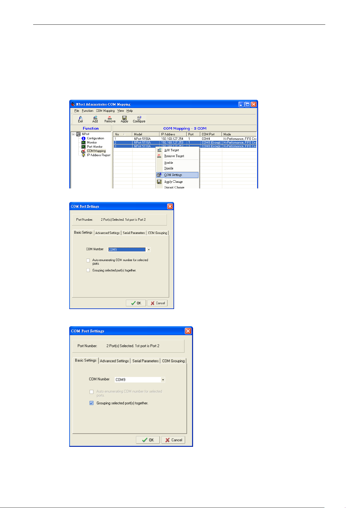
NPort 5600-8-DT/DTL Series Using NPort Administrator
8-25
www.ipc2u.ru
www.moxa.pro
Modifying Ports in a COM Group
In the following subsections we examine three ways in which the serial ports in a COM Group can be modified:
Changing the COM Number of a COM Group
1. Select all ser i al ports in the Group and rig ht-clic k to select COM Settings.
2. Select a COM number that is not in use or assig ne d to a Group.
3. Select the Grouping selected port(s) together checkbox and then click OK.
Page 81

NPort 5600-8-DT/DTL Series Using NPort Administrator
8-26
www.ipc2u.ru
www.moxa.pro
4. You will be able to view the serial ports that were assigned to and removed from the Group. Click Apply to
apply the settings.
5. Finally, clic k Yes to confirm.
Changing Advanced Settings and Serial Parameters of the COM Group
1. Check the port spec ifie d o n the COM Grouping page as the signal port.
2. Select the ”S ignal S tatus ” controlled port and then right-click and select COM Settings.
Page 82
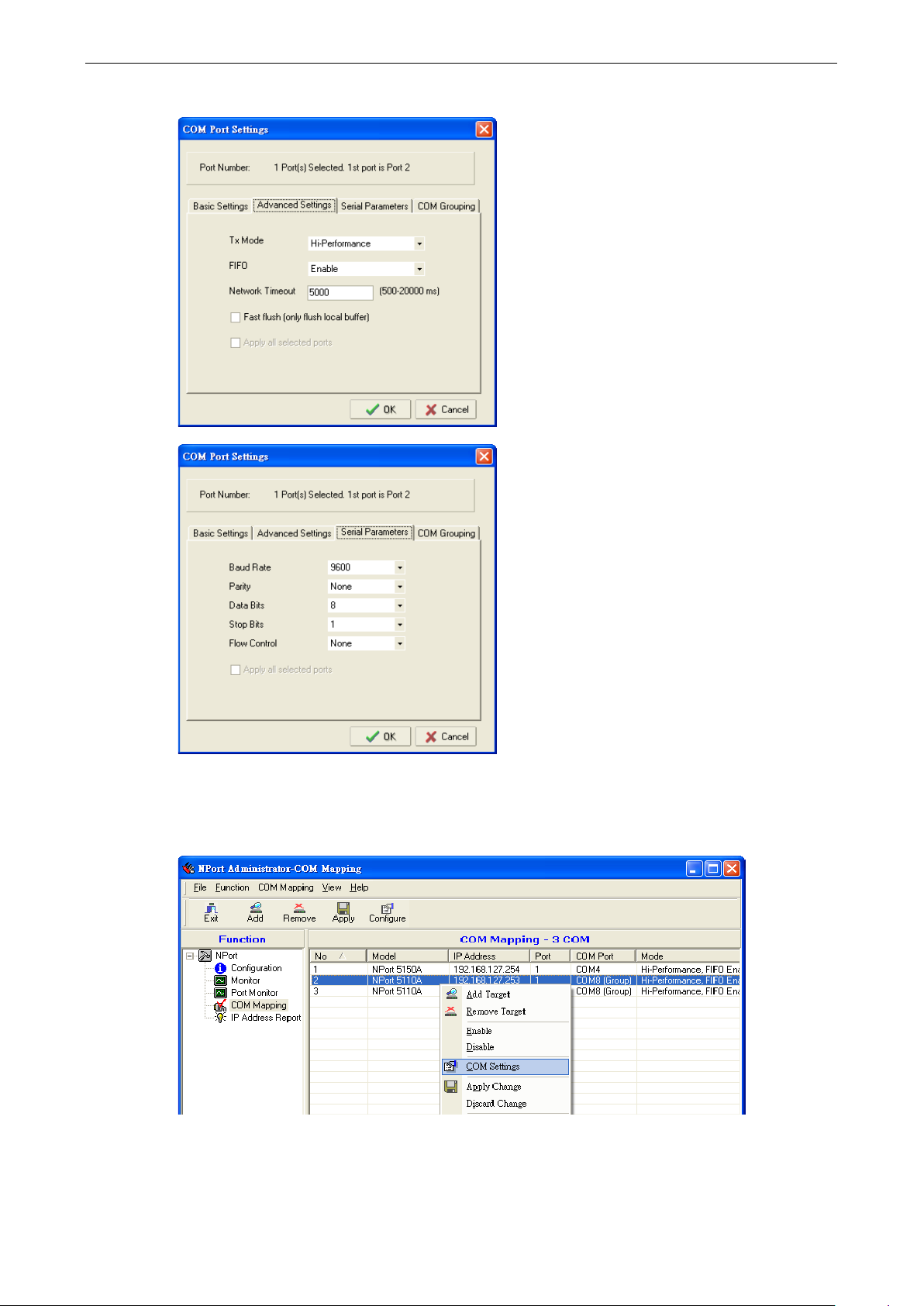
NPort 5600-8-DT/DTL Series Using NPort Administrator
8-27
www.ipc2u.ru
www.moxa.pro
3. The Advanced Settings and Serial Parameters pages will be available for modification.
Changing the Serial Port Specified as Signal Port for the COM Group
1. Selecta ser ia l port in the Gro up and then right-cl ic k and s e lect COM Settings.
Page 83
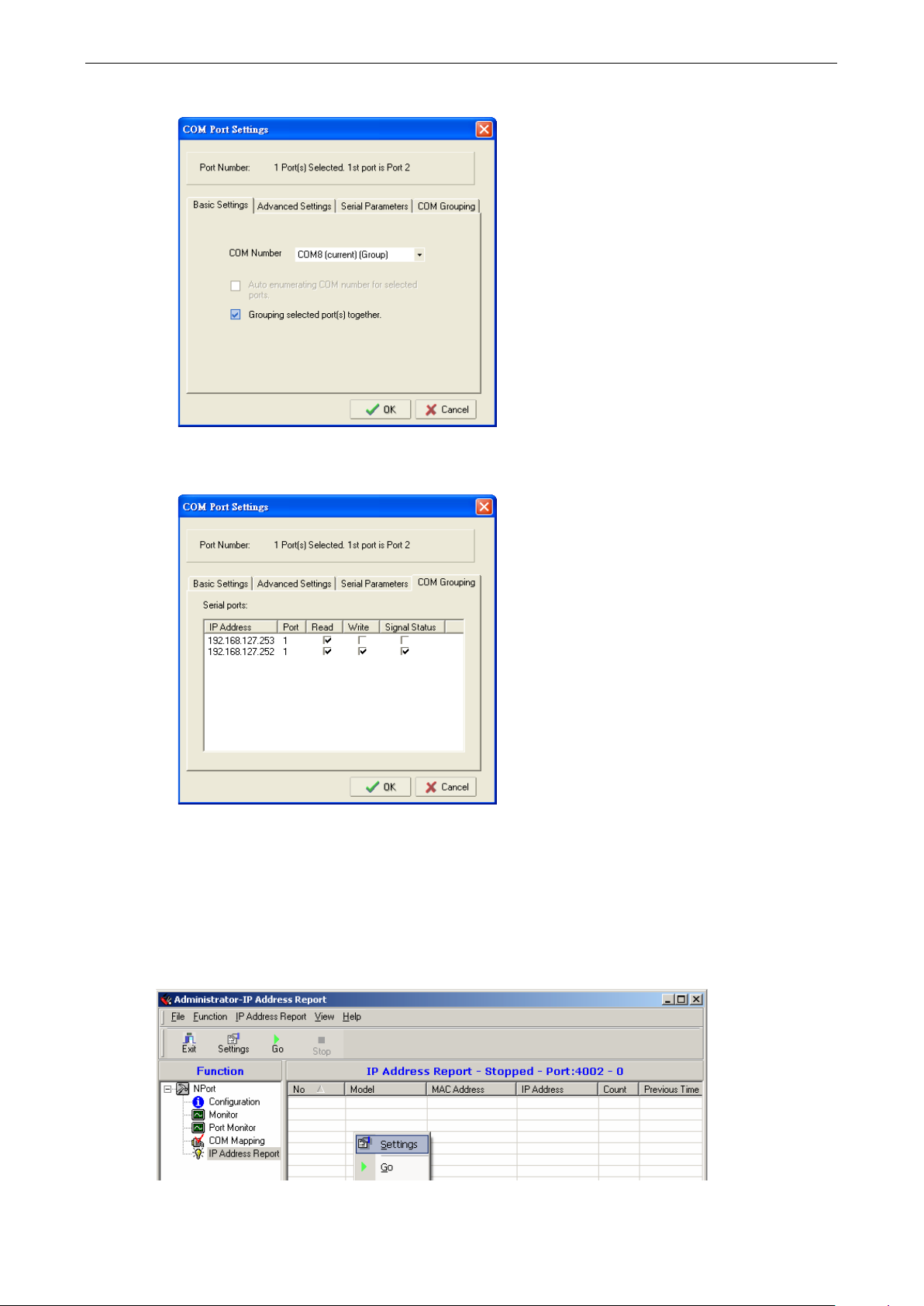
NPort 5600-8-DT/DTL Series Using NPort Administrator
8-28
www.ipc2u.ru
www.moxa.pro
2. Check the Grouping selected port(s) together check box.
3. On COM Group ing page, you can specify one serial port whose signals will b e take n into ac count by the
COM Group and change the Read/Write status for each serial port.
IP Address Report
The IP Address Report function receives automatic IP reports from appropriately configured NPort device
servers. Use the Settings command in the function context menu to designate the UDP port number that the
NPort will use when sending IP address reports. This must correspond with the network settings on the NPort
device server.
Page 84
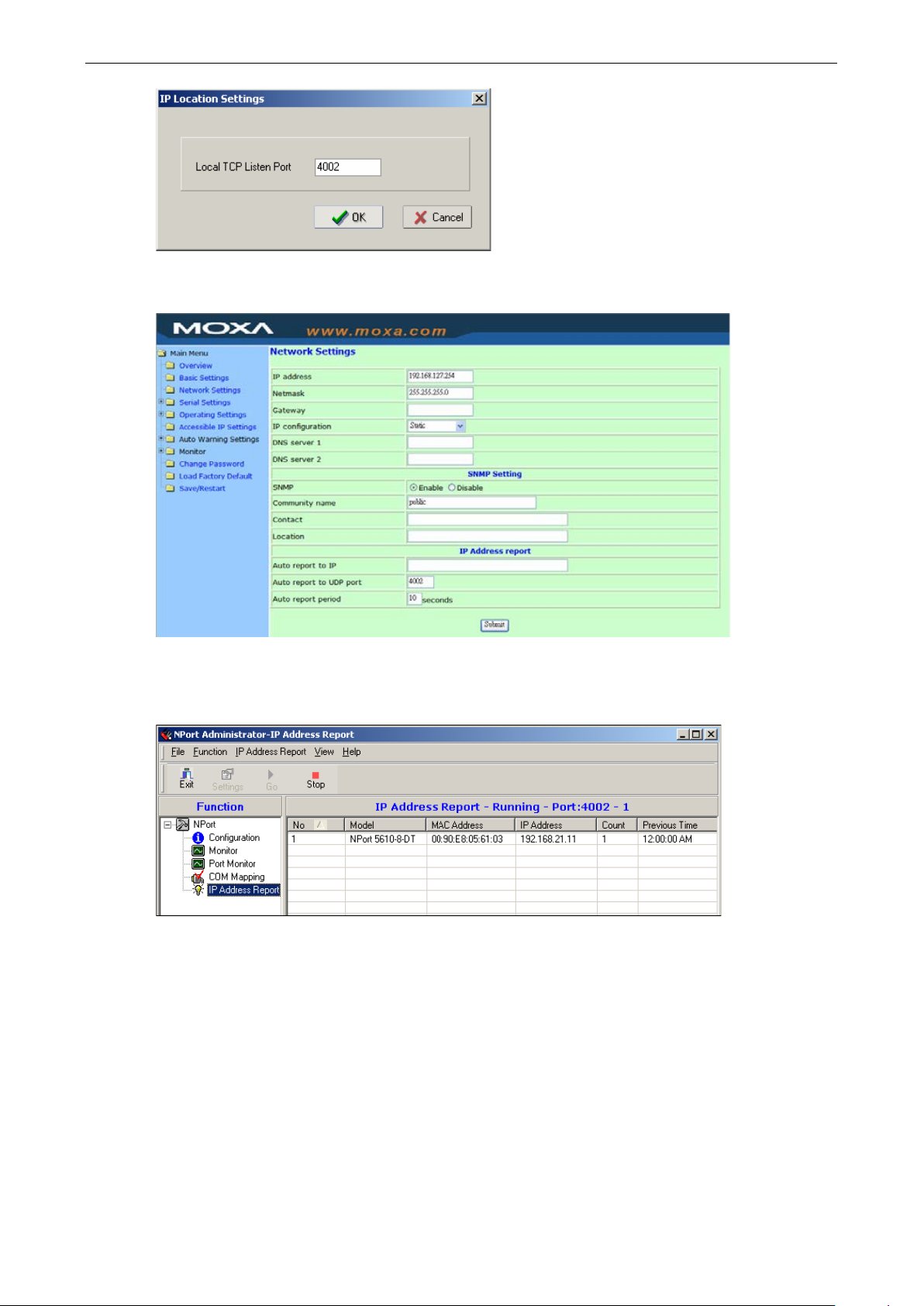
NPort 5600-8-DT/DTL Series Using NPort Administrator
8-29
www.ipc2u.ru
www.moxa.pro
On the NPort device server, the Auto report to IP parameter must be set to the IP address of the PC that is
running NPort Administrator .
Select Go from the function context menu to begin monitoring for IP add re s s repor ts . The IP Addr ess Repor t
window will begin displaying IP reports as they are received. Select Stop from the context menu to suspend
monitoring, and Clear to clear the curre nt d i splay of repor ts .
Please refer to Chapter 4 for information on configuring the NPort to send automatic IP reports. Please refer to
Appendix C for information on the IP report protocol.
Automatic Message Log
When NPort Administrator is closed, all activity in that session is saved in a log file in the installation directory.
Log files are generated in sequence, starti ng with file message_0.log. After file message_9.log, the next
log file will start over again at file message_0.log.
Page 85

9
www.ipc2u.ru
www.moxa.pro
9. NPort CE Driver Manager for Windows CE
The following topics are covered in this chapter:
Overview
Installing NPort CE Driver Manager
Using NPort CE Driver Manager
Page 86
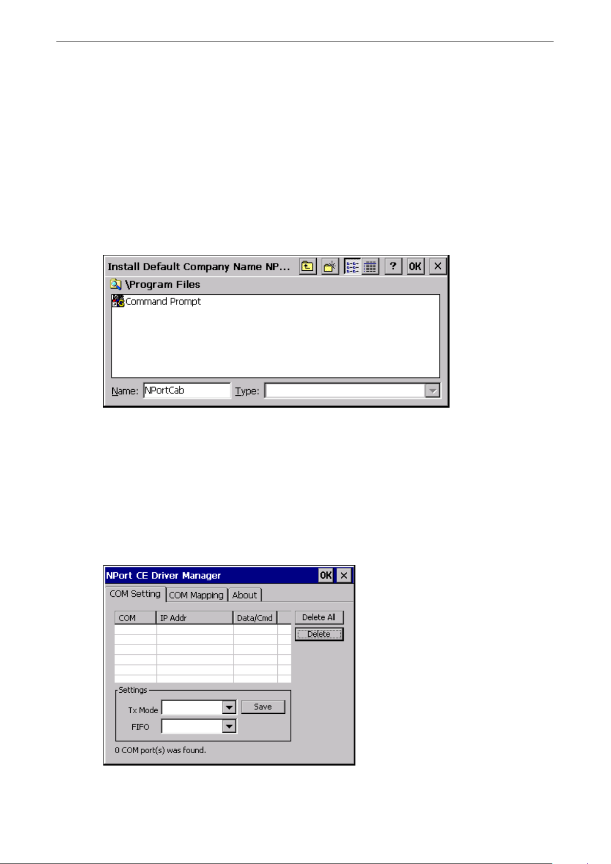
NPort 5600-8-DT/DTL Series NPort CE Driver Mana ger for Windows CE
9-2
www.ipc2u.ru
www.moxa.pro
Overview
NPort CE Driver Manager is designed for use with NPort 5000 serial ports that are set to Real COM mode. The
software manages the installation of drivers that allow you to map unused COM ports on your PC to serial ports
on the NPort 5000. These drivers are designed for use with Windows CE 5.0/6.0. When the drivers are installed
and configured, devices that are attached to serial por ts on the NPor t 5000 will be tre ate d as if they were
attached to your PC’s own COM ports.
Installing NPo rt CE Driver Manager
Copy “NPortCab.cab” to Windows CE and start to install driver by double clicking on it.
Click on “OK” to complete the installation when the following screen appears.
Driver installation is now complete and the “NPortCab.cab” icon disappear from the screen. This is normal when
installing drivers in Windows CE.
Using NPort CE Driver Manager
After you install NPort CE Driver Manager, you can set up the NPort’s serial ports as remote COM ports for your
Windows CE. Make sure that the serial port(s) on your NPort are set to Real COM mode when mapp ing COM
ports with NPort CE Driver Manager.
Go to Start Programs NPort CE Driver Manager.
Page 87
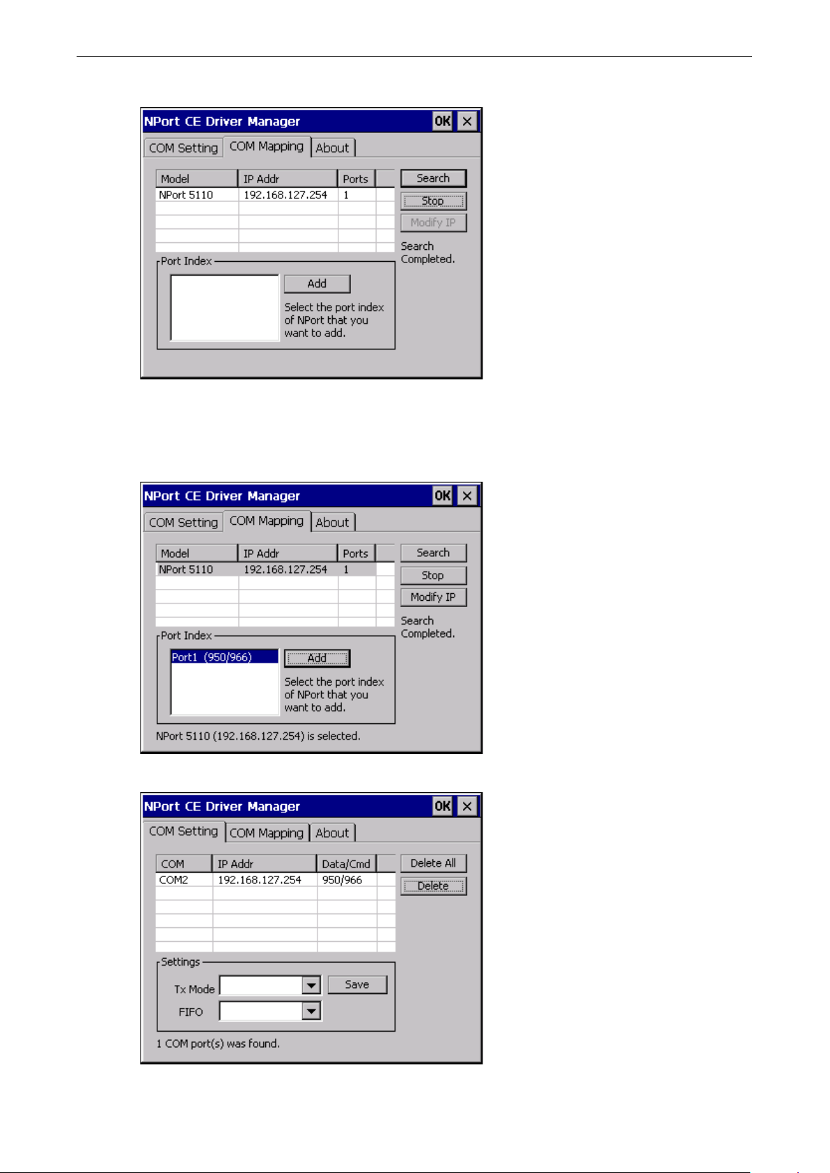
NPort 5600-8-DT/DTL Series NPort CE Driver Mana ger for Windows CE
9-3
www.ipc2u.ru
www.moxa.pro
Click on the COM Mapping page and then the “Search” button to scan for NPort servers.
All NPort servers that were located will app e ar in the NPort CE Driver Manager window. Click on the server
whose COM ports you would like to map to and then select the port index. Note that multiple sele c tions are
allowed.
Select the port(s) at the Port Index and then click on the “Add” button to map to the COM Por t(s ).
Return to the COM Setting page. You should be able to see the newly mapped COM Por t(s).
Page 88
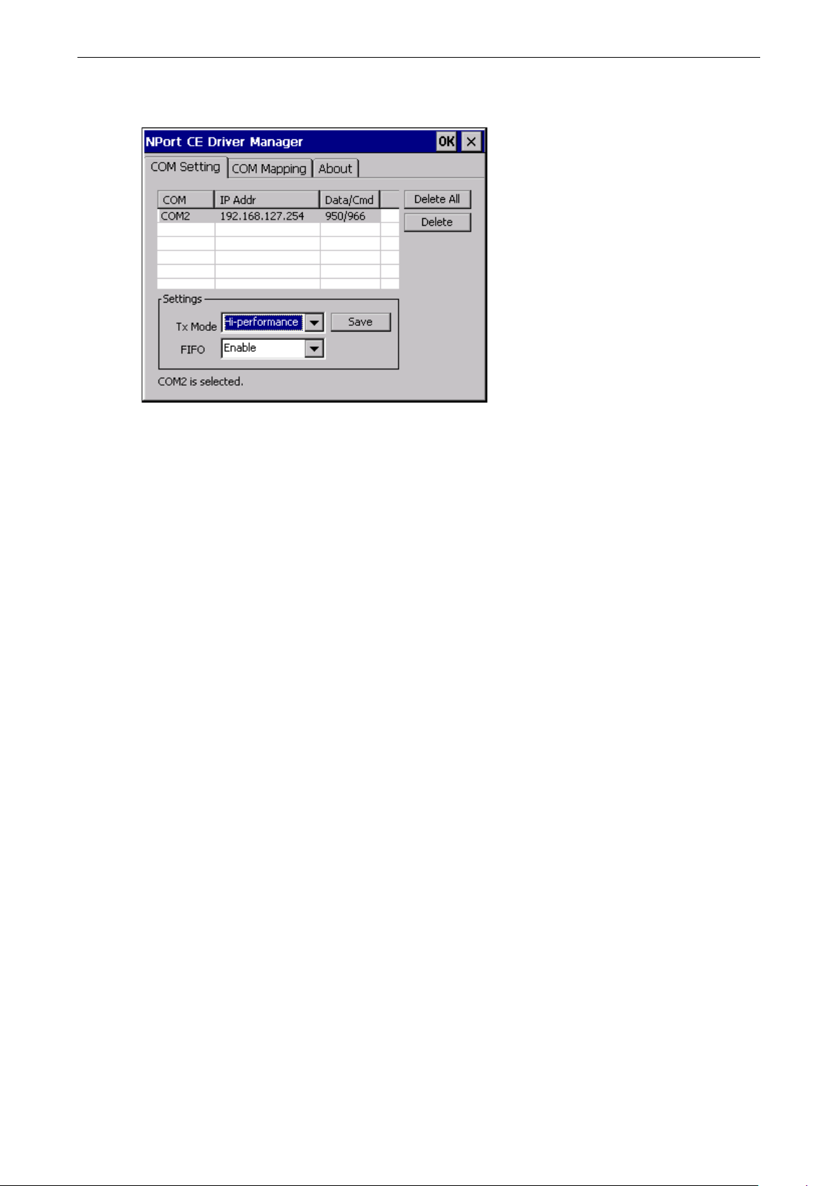
NPort 5600-8-DT/DTL Series NPort CE Driver Mana ger for Windows CE
9-4
www.ipc2u.ru
www.moxa.pro
To configure the settings for a particular COM Port, sele c t the row of the desired port, and then modify the
setting in the “Settings” panel, as shown below .
Tx Mode
“Hi-Performance” is the default for Tx mode. After the driv er se nds data to the NPor t server, the driver
immediately issues a “Tx Empty” response to the program. Under “Classical mode,” the driver will not send the
“Tx Empty” response until after confirmation is received from the NPort server’s serial port. This causes lower
throughput. Classical mode is recomm e nded if you want to ensure that all data is sent out before further
processing.
FIFO
If FIFO is disabled, the NPort server will transmit one byte each time the Tx FIFO becomes empty, and an Rx
interrupt will be generated for each incoming byte. This will result in a faster response and lower throughput.
Page 89

10
www.ipc2u.ru
www.moxa.pro
10. Other Configuration Interfaces
The following topics are covered in this chapter:
Overview
LCM Console (applies to DT models only)
Main Menu Server setting
Main Menu Network setting
Main Menu Serial set
Main Menu Op Mode set
Main Menu Console
Main Menu LCM passwd prot
Main Menu Reset btn prot
Main Menu Ping
Main Menu Save/Restart
Telnet Console
Serial Console (NPor t 56 00 -8-DT)
Serial Console (NPort 5600-8-DTL)
Page 90

NPort 5600-8-DT/DTL Series Other Configuration Interfac es
10-2
www.ipc2u.ru
www.moxa.pro
Overview
Typically, you will use either NPort Adminis tr a tor or the web console to configure the NPort 5600-8-DT/DTL.
These are not the only options for configuratio n. For basic onsi te configuration, you can use the LCM console
built into the device server, without requiring a connection to the network or a laptop. You may also connect to
the serial console over the serial console port (port 1 for DTL models), or to the Telnet console over one of the
Ethernet ports.
LCM Console (appl ies to DT models on ly)
The LCM console refers to the LCD control panel on the top panel of the NPort 5600-8-DT. The LCM console can
be used to view and m odif y ba sic sett ings, su ch as IP add ress. The MENU button activates the main menu. It
is also used to cancel a selection and return to a previous menu. The UP and DOWN buttons navigate between
available options. The SEL button se le c ts an option or enters a submenu.
Main Menu Server setting
Under Server settin g, you can view basic information about your device server. T he followi ng fie ld s are
displayed:
• Serial number
• Server n a me
• Firmware ver
• Model name
Main Menu Network setting
Under Network setting, you can view the device server’ s network se ttings and modify certain parameters
such as IP address. The following fields are displayed:
• Ethernet1 statu
• Ethernet2 statu
• MAC address
• IP config
• IP address
• Netmask
Main Menu Serial set
Under Serial set, you can view each device port’s serial communication setting s and modify certain
parameters such as baud rate. Settings are displayed and modified on a port-by-port basis. You will first select
the port that you wish to modify or view. The following fie lds are disp layed:
• Baud rate
• Data bit
• Stop bit
• Parity
• Flow control
• Tx/Rx fifo
• Interface
• Tx/Rx bytes
• Line status
Page 91

NPort 5600-8-DT/DTL Series Other Configuration Interfac es
10-3
www.ipc2u.ru
www.moxa.pro
Main Menu Op Mode set
Under Op Mode set, you can view or modify each device port’s operation mode. You will first select the port
that you wish to modify or view. Note that you can only select the operation mode. You will not be able to view
or modify the advanced operation mode settings through the LCM console.
Main Menu Console
Under Console, you can enable or disable the web and Telnet consoles. The follow ing fie ld s are disp layed:
• Web console
• Telnet console
Main Menu LCM passwd prot
LCM passwd prot refer s to passwo rd p rotection for the LCM. If password protection is enabled, users will be
required to enter the password in order to use the LCM console.
Main Menu Reset btn prot
Reset btn prot refers to reset button protection. If reset button protection is enabled, you will only be able to
use the reset button in the first 60 seconds after powering on the NPort. After 60 seconds, the reset button will
be disabled.
Main Menu Ping
You can use the built-in Ping function to verify network operation. Enter the IP address that you wish to ping
and check the LCD screen for the response.
Main Menu Save/Restart
If any configuration changes are made thro ugh the LCM, you will nee d to Save/Restart for the changes to
take effect.
Telnet Console
You can use Telnet to open a terminal session with the NPort 5600-8-DT/DTL over one of the Ethernet ports.
Simply Telnet to your device server’s IP address. You will be presented with a text menu displaying the NPort
5600-8-DT/DTL’s general settings, which you will be able to view and modify. Please ref er to Chapter 4 for a
description of the available settings.
Serial Console (N P ort 5600-8-DT)
If you are unable to connect to the Telnet console, it may be because it has been dis abled thro ug h the LCM
console.
You can connect to the serial console port to open the serial conso le . Co nne c t to the console port w ith a
serial-based terminal or terminal emulator program, such as Windows HyperTerminal. You may also download
PComm Lite at
communication parameters should be set as 19200, 8, N, 1 (19200 for baud ra te , 8 for data bits, None for
parity, and 1 for stop bits). As soon as the connection is open, you will be presented with a text menu displaying
the NPort 5600-8-DT’s general settings. Please r efer to Chapte r 4 for a descr iption of the available settings.
www.moxa.com. The terminal type should be set as ANSI or VT100, and the serial
Page 92

NPort 5600-8-DT/DTL Series Other Configuration Interfac es
10-4
www.ipc2u.ru
www.moxa.pro
Serial Console (N P ort 5600-8-DTL)
You may use the RS-232 console port to set up the IP address for NPort 5600-8-DTL. We suggest using PComm
Terminal Emulator, which is available fr ee of charg e as par t of the PComm Lite pro gr am suite (fo und o n the
Software CD that comes with the product), to carry out the installati o n p rocedure, although other similar
utilities may also be used.
Before you start to configure the NPort 5600-8-DTL via serial console, turn off the power and connect the serial
cable from NPort 560 0-8-DTL to your computer’s serial port.
1. Connect NPort 5600-8-DTL’s serial po rt 1 directly to your computer’s male RS-232/422/485 serial port.
2. From the Windows desk top , click Start Programs PComm Lite Terminal Emulator.
3. When the PComm Terminal Emulator window opens, first click on the Port Manager menu item and
select Open, or simply click on the Open icon.
4. The Property window opens automatically. Fro m the Communication Parameter page, select the
appropriate COM port for the connection, COM1 in this example, and 19200 for Baud Rate, 8 for Data
Bits, None for Parity, and 1 for Stop Bits.
5. From the Property window’s Terminal page, select ANSI or VT100 for Terminal Type and then click OK.
If you select Dumb Terminal as the terminal type, some of the console functions—espe c ially the “Monitor”
function—may not work properly.
6. Press the “ ` ” key continuously and then po wer o n the NPort 560 0-8-DTL.
7. The NPor t 5600-8-DTL will receive the “ ` ” string continuously and then auto switch from data mode to
console mode.
8. Input the password when prompted. Note that this page will only appear when the NPort 5600-8-DTL has
been set up for password protection.
9. Start configuring the IP address under Network Settings. Refer to step 4 in the Telnet Console section
for the rest of the IP settings.
Page 93

NPort 5600-8-DT/DTL Series Other Configuration Interfac es
10-5
www.ipc2u.ru
www.moxa.pro
Page 94

11
www.ipc2u.ru
www.moxa.pro
11. TTY Drivers for Linux and UNIX
The following topics are covered in this chapter:
Linux Real TTY Drivers
Basic Steps
Installing Linux Real TTY Driver Files
Mapping TTY Ports
Removing Mapped TTY Ports
Removing Linux Driver Files
UNIX Fixed TTY Dri ve rs
Installing the UNIX Driver
Configuring the UNIX Driver
Page 95

NPort 5600-8-DT/DTL Series TTY Drivers for Li nu x a nd UNIX
11-2
ATTENTION
The target device port must be operating in Real COM mode i
www.ipc2u.ru
www.moxa.pro
Linux Real TTY Drivers
Real TTY driver are provided that will map Linux host TTY por ts to NPort device ports. Once the mapping has
been set up, Linux users and applications can connect to a device port as if it were a local TTY port. These
drivers have been designed and tested for the majority of Linux dis tributions, including Linux kerne l vers ion
2.4.x and 2.6.x. Please check Moxa’s website (
more detail, please refer to README.TXT.
Basic Steps
Follow these instructions to map a TTY port to a device port:
Install the NPort device server and set the target devic e port to Rea l COM mode.
Install the Real TTY driver files on the Linux host.
Map the host’s TTY port to the target device port on the NPort.
Installing Linux Real TTY Driver Files
Before proceeding with the software installati o n, ma k e sur e you have comple te d the N Port dev ic e serv er has
been installed and configured corr e c tly . Note that the default IP address for the NPort is 192.168.127.254.
http://www.moxa.com) for the latest Linux kernel support. For
1. Obtain the drive r f ile from the Document and Software CD, or from the Moxa website at
http://www.moxa.com.
2. Log in to the console as a super user (root).
Execute cd / to go to the root directory.
Copy the driver file npreal2xx.tgz to the / directory.
Execute tar xvfz npreal2xx.tgz to extract all files into the syste m .
Execute /tmp/moxa/mxinst.
For RedHat AS/ES/WS and Fedora Core1, append an extra argume nt as follow s :
# /tmp/moxa/mxinst SP1
The shell script will install the drive r f ile s auto matic a lly.
After installing the driver, you will b e abl e to see severa l files in the /usr/lib/npreal2/driver folder:
> mxaddsvr (Add Server, mapping tty port)
> mxdelsvr (Delete Server, un-mapping tty port)
> mxloadsvr (Reload Server)
> mxmknod (Create device node/tty port)
> mxrmnod (Remove device node/tty port)
> mxuninst (Remove tty port and driver files)
n order to map TTY ports.
At this point, you may map the TTY port to the NPort serial port.
Mapping TTY Ports
Make sure that you set the operation mode of the desired NPort serial port to Real COM mode. After logging in
as a super user, enter the directory /usr/lib/npreal2/driver and then execute mxaddsvr to map the target
NPort serial port to the host TTY ports. The syntax of mxaddsvr is as follows :
mxaddsvr [NPort IP Address] [Total Ports] ([Data port] [Cmd port])
Page 96

NPort 5600-8-DT/DTL Series TTY Drivers for Li nu x a nd UNIX
11-3
www.ipc2u.ru
www.moxa.pro
The mxaddsvr command performs the following actions:
1. Modify npre al2d.cf.
2. Create TTY ports in dir ectory /dev with major and minor number configured in npreal2d.cf.
3. Restart the driver.
Mapping TTY ports automatic all y
To map TTY ports automatically, you may execute mxaddsvr with just the IP address and number of ports, as
in the following example:
# cd /usr/lib/npreal2/driver
# ./mxaddsvr 192.168.3.4 16
In this example, 16 TTY ports will be added, all with IP 192.168.3.4, with data po r ts from 950 to 965 and
command ports from 966 to 981.
Mapping TTY ports manuall y
To map TTY ports manually, you may execute mxaddsvr and manually specify the data and command ports,
as in the following example:
# cd /usr/lib/npreal2/driver
# ./mxaddsvr 192.168.3.4 16 4001 966
In this example, 16 TTY ports will be added, all with IP 192.168 .3.4, with data ports from 4001 to 4016 and
command ports from 966 to 981.
Removing Mapped TTY Port s
After logging in as root, enter the directory /usr/lib/npreal2/driver and then execute mxdelsvr to delete
a server. The syntax of mxdelsvr is:
mxdelsvr [IP Address]
Example:
# cd /usr/lib/npreal2/driver
# ./mxdelsvr 192.168.3.4
The following actions are performed when executing mxdelsvr:
1. Modify npre al2d.cf.
2. Remove the relevant TT Y ports in directory /dev.
3. Restart the driver.
If the IP address is not provided in the command line, the program will list the installed servers and total ports
on the screen. You will need to choose a server from the list for deletion.
Removing Linux Driver Files
A utility is included that will remove all driver files, mapped TTY ports, and unload the driver. Enter the directory
/usr/lib/npreal2/driver, then execute mxuninst to uninstall the driver. This program will perform the
following actions:
1. Unload the driv er.
2. Delete all files and directories in /usr/lib/npreal2.
3. Delete directory /usr/lib/npreal2.
4. Modify the system initiali zing script file.
Page 97

NPort 5600-8-DT/DTL Series TTY Drivers for Li nu x a nd UNIX
11-4
www.ipc2u.ru
www.moxa.pro
UNIX Fixed TTY Drivers
A fixed TTY driver is provided that will map UNIX host TTY ports to NPort device ports. Once the mapping has
been set up, UNIX users and applications can connect to a device port as if it were a local TTY port. This driver
has been designed and tested for the majority of UNIX systems. Please check Moxa’s website
(http://www.moxa.com) for the latest U NI X syste ms support. Fo r mor e detail, p le as e r efer to README.TX T.
Installing the UNIX Driver
1. Log in to UNIX and create a directory for the Moxa TTY. To create a directory named /usr/etc, execute the
command:
# mkdir –p /usr/etc
2. Copy moxattyd.tar to the directory you created. For the /usr/etc directory, you would execute the
following commands:
# cp moxattyd.tar /usr/etc
# cd /usr/etc
3. Extract the so urc e file s from the tar file by exec uting the command:
# tar xvf moxattyd.tar
The following files will be extracted :
README.TXT
moxattyd.c --- source code
moxattyd.cf --- an empty configuration file
Makefile --- makefile
VERSION.TXT --- fixed tty driver version
FAQ.TXT
4. Compile and link.
For SCO UNIX:
# make sco
For UnixWare 7:
# make svr5
For UnixWare 2.1.x, SVR4.2:
# make svr42
Configuring the UNIX Driver
Modify the configuration:
The configuration used by moxattyd is defined in the text file moxattyd.cf, which is in the same directory.
You may use vi or any text editor to modify the file, as follows:
ttyp1 192.16 8. 1.1 950
You can refer to moxattyd.cf for detailed descriptions of the various configuration parameters. Please note
that “Device Name” depends on the OS. See the Device Naming Rule section in README.TXT fo r mor e
information.
To start the moxattyd daemon after system bootup, add an entry into /etc/inittab using the TTY name you
defined in moxattyd.cf, as in the fol lo wing example:
ts:2:respawn:/usr/etc/moxattyd/moxattyd –t 1
Device naming rule
For UnixWare 7, UnixWare 2.1.x, and SVR4.2, use:
pts/[n]
For all other UNIX operating systems, use:
ttyp[n]
Page 98

NPort 5600-8-DT/DTL Series TTY Drivers for Li nu x a nd UNIX
11-5
www.ipc2u.ru
www.moxa.pro
The value of [n] should be equal or larger than 11 in order to prevent conf l ic ts with the device name s of
functional keys in some UNIX systems.
Starting moxattyd Execute the command init q or reboot your UNIX operating system.
Adding an additional serve r
Modify the text file moxattyd.cf to add an additional server. User may use vi or any text editor to modify the
file. For more configuration infor mati o n, refe r to moxattyd.cf, which contains detaile d descriptions of the
various configuration parame ters .
Find the process ID (PID) of the moxattyd.
# ps -ef | grep moxattyd
Update the configuration of moxattyd.
# kill -USR1 [PID]
(e.g., if moxattyd PID = 404, kill -USR1 404)
This completes the process of adding an additional se rv er.
Page 99

12
www.ipc2u.ru
www.moxa.pro
12. The IP Serial Library
The following topics are covered in this chapter:
Overview
IP Serial Library Function Groups
Example Program
Page 100
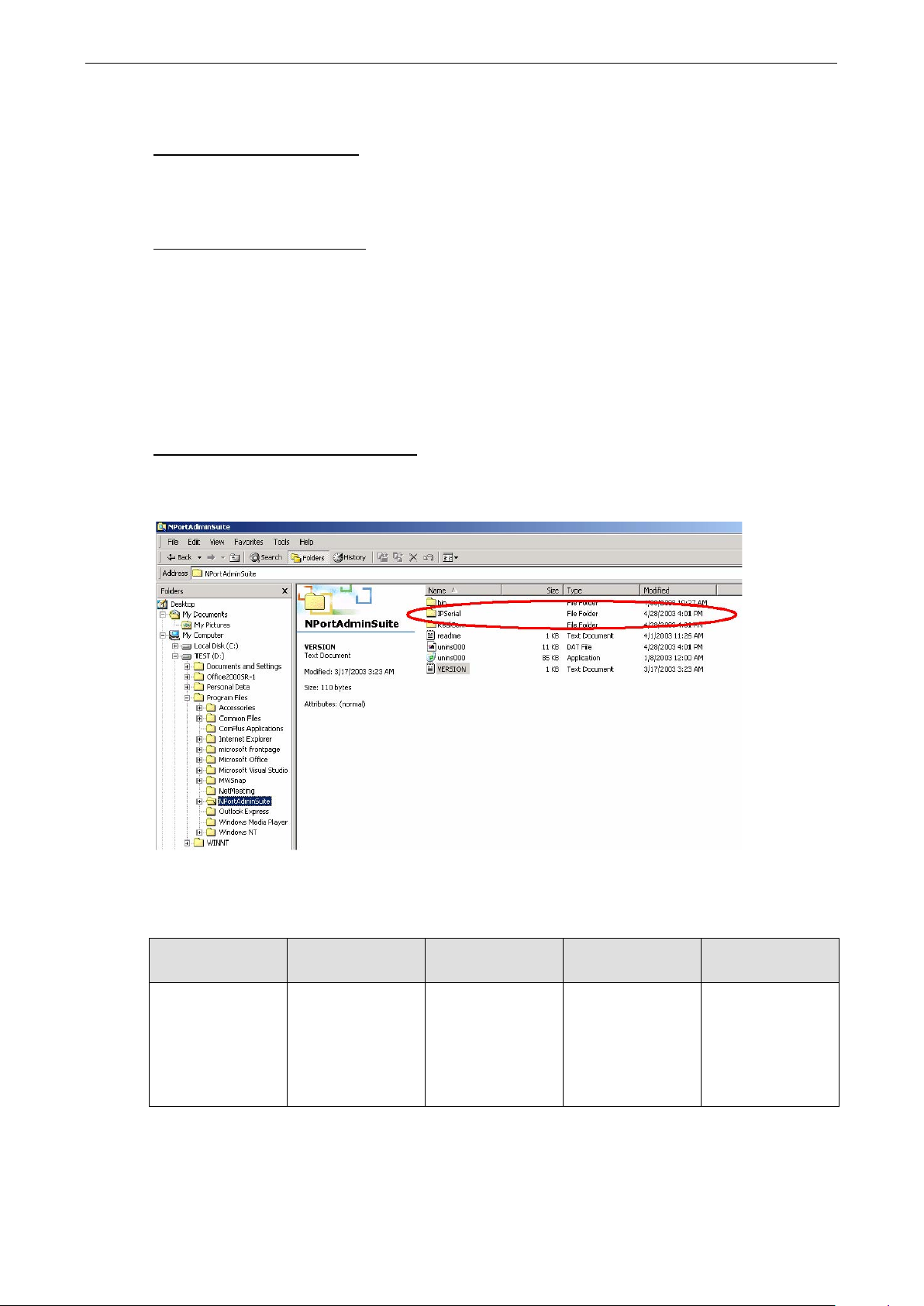
NPort 5600-8-DT/DTL Series The IP Serial Library
12-2
www.ipc2u.ru
www.moxa.pro
Overview
What is the IP Serial Library?
The IP Serial Library is a Window s library with frequently used serial command sets and subroutines. It is
designed to reduce the complexity and improve the effic ie nc y of serial communication over TCP/IP. For
example, Telnet can transfer data but cannot monitor or config ure the serial line’s parameters.
Why use the IP Ser ial Library?
For programmers who are familiar with serial communic ation, the IP Serial Library provides well-designed
function calls in the style of Moxa’s PComm Library. It is simple and easy for programmers to understand. You
can include the library in your Visual Basic, C, or Delphi programming environment and easily develop your own
TCP/IP application with the ability to control serial communication parameters.
With the Real COM driver, two TCP ports are required for communicatio n b e tw een the NPort and the host
computer. The IP Serial Library requires one command port to comm unic ate w i th the NPort. Ser i al
communication can be controlled with just one TCP port (e.g., RFC 2217). The IP Serial Library not only runs
with excellent efficiency but also runs witho ut any d ecode or encode problems.
How do I install the IP Serial Library?
The IP Serial Library comes with the NPort Administr ati o n Suite. Ple a s e refer to the IP Serial directory for
details about the available functions .
IP Serial Library Fu n ction Groups
Server Control Port Control Input/Output
Data
nsio_init
nsio_end
nsio_resetserver
nsio_checkalive
nsio_open
nsio_close nsio_ioctl
nsio_flowctrl
nsio_DTR nsio_RTS
nsio_lctrl nsio_baud
nsio_resetport
nsio_read
nsio_SetReadTimeo
uts nsio_write
nsio_SetWriteTimeo
uts
Port Status
Inquiry
nsio_lstatus
nsio_data_status
Miscellaneous
nsio_break
nsio_break_on
nsio_break_off
nsio_breakcount
 Loading...