

Page 1
– 1 – – 2 – – 3 –
P/N: 1802056001012
NPort 5600-8-DT
Quick Installation Guide
Third Edition, May 2014
Overview
The NPort 5600-8-DT series includes the following models :
NPort 5610-8-DT: 8 ports, RS-232, DB9
NPort 5610-8-DT-J: 8 ports, RS-232, RJ45
NPort 5650-8-DT: 8 ports, RS-232/422/485, DB9
NPort 5650-8-DT-J: 8 ports, RS-232/422/485, RJ45
NPort 5650I-8-DT: 8 por ts, RS-232/422/485, DB9, optical
isolation
Package Checklist
The NPort 5600-8-DT package should contain the following items:
• NPort 5600-8- DT 8-port serial device server
• Power cord and adapter
• DIN rail kit
• NPort documentation and software CD
• NPort 5600-8- DT Quick Installation Guide
Optional Accessories:
DK-35A: DIN rail mount ing kit (35 mm)
CBL-RJ45M9-150: 8-pin RJ45 to male DB9 cable, 150 cm
CBL-RJ45F9-150: 8-pin RJ45 to female DB9 cable, 150 cm
CBL-RJ45M25-150: 8-pin RJ45 to male DB25 cable, 150 cm
CBL-RJ45F25-150: 8-pin RJ45 to female DB25 cable, 150 cm
NP21101: DB25-M to DB9-F RS-23 2 cable, 30 cm
Please notify your sales representative if any of the above items
are missing or damaged.
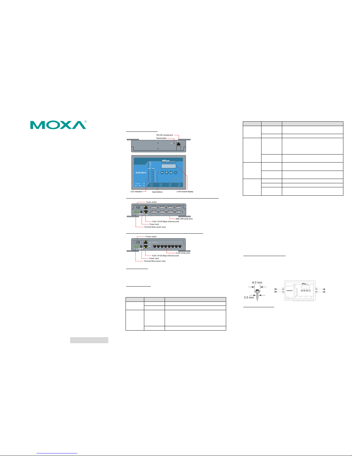
Hardware Introduction
Top and Rear View
Front View (NPort 5 610-8-DT, 5650-8-DT, 5650I-8-D T)
Front View (NPort 5 610-8-DT-J, 5650-8- DT-J)
Reset Button
The reset button is used to load the factory defaults. Use a pointed
object to hold the reset button down for five seconds. You may
release the reset button when the Ready LED stops blinking.
LED Indicators
The LED indicators on the top panel are used to display status as
follows:
Name
Color
Function
PWR
red
Power is on.
off
Power is off.
Ready
green
Steady:
NPort is operational
Blinking: NPort is responding to NPort
Administrator “Locate”
function
off
Power is off or fault condition exists.
Name
Color
Function
Fault
red
IP conflict or DHCP or BOOTP server did
not respond properly.
off
No fault condition detected.
Link
green
Steady:
Network is connected, no data
is being tra nsmitted.
Blinking:
Network is connected, data is
being transmitte d.
off
Ethernet cable is disconnected or has a
short.
InUse
(P1 to P8)
green
Serial port has been opened by server
side software.
off
Serial port is not currently opened by
server side software.
Tx/Rx
(P1 to P8)
green (Tx)
Serial device is transmitting d ata.
orange (Rx)
Serial device is receiving data .
off
No data is flowin g to or from the serial
port.
Hardware Installation
STEP 1: After removing the NPort 5600-8-DT from the box, place
it on a desktop or other horizontal surface. Connect the 12-48 VDC
power adaptor to the NPort 5600-8-DT’s power input when using
an AC power source, or connect the NPort 5600-8-DT’s terminal
block directly to a DC power source.
STEP 2: Use an Ethernet cable to connect the NPort 5600-8-DT to
a network hub or switch. You can also connect directly to your
computer’s Ethernet port, which is convenient for initial
configuration or testing.
STEP 3: Connect the NPort 5600-8-DT’s serial port to a serial
device.
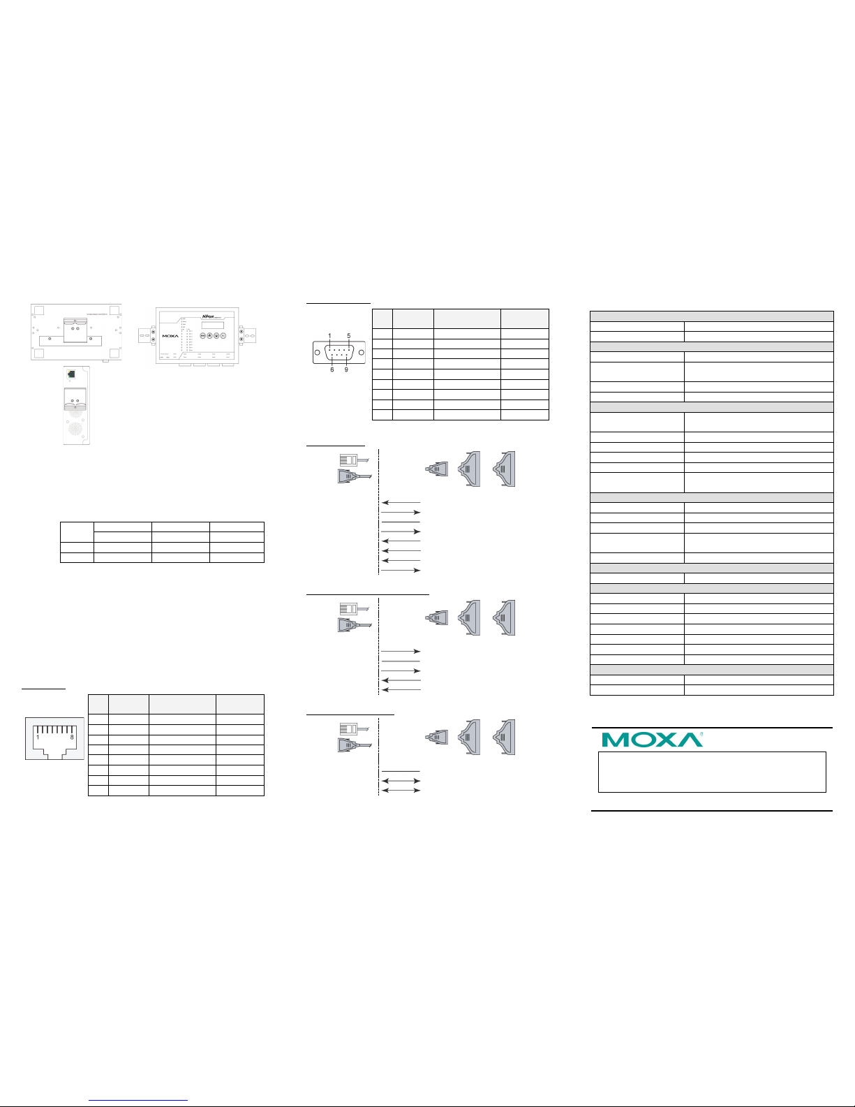
Wall or Cabinet Mounting
The NPort 5600-8-DT comes with two metal attachment plates to
allow installation on a wall or the inside of a cabinet. First, attach
the brackets to the back of the NPort with screws. Next, mount the
unit on a wall or cabinet with screws. Screws should be less than
6.0 mm in head d iameter, and les s than 3.5 mm in shaft diameter.
DIN Rail Mounting
DIN-rail attachments can be purchased separately to attach the
product to a DIN-rail. The DIN-rail attachments should be oriented
with the metal springs on top.
Page 2
– 4 – – 5 – – 6 –
www.moxa.com/support
The Americas:
+1-714-528-6777 (toll-free: 1-888-669-2872)
Europe:
+49-89-3 70 03 99-0
Asia-Pacific:
+886-2-8919-1230
China:
+86-21-5258-9955 (toll-free: 800-820-5036)
2014 Moxa Inc. All r ights reserved.
Standard Attachment
DK-35A Attachment
Pull High/Low Resistors for RS-485
Use the set of DIP switches on the bottom panel to set the pull
high/low resistor values for each serial port. To access the
switches, remove the screws holding the DIP switch cover in place
and flip open the cover. There are three DIP switches for each
port’s pull high/low resistors:
SW
1 2 3
Pull High
Pull Low
Terminator
ON
1KΩ
1KΩ
120Ω
Default
OFF
150KΩ
150KΩ
---
Software Installation Information
To install NPort Administration Suite, insert the NPort
Document & Softwa re CD into your PC’s CD-ROM drive. Locate
and run the setup program and follow the on-screen instructions.
The setup program wi ll be named
Npadm_Setup_[Version]_ Build_[Dat eTime].e xe (e.g., “Npadm
_Setup_Ver1.8 _Build_070413 16.exe”). For more information
about NPort Administration Suite, please refer to the NPort
5600-8-DT User’s Manual.
Pin Assignments and Cable Wiring
RJ45 Ports (NPort 5610-8-DT-J, 5650-8-DT -J)
Pin RS-232
RS-422
4-wire RS-485
2-wire
RS-485
1
DSR
---
---
2
RTS
TxD+
---
3
GND
GND
GND 4 TxD
TxD-
---
5
RxD
RxD+
Data+
6
DCD
RxD-
Data- 7 CTS
---
---
8
DTR
---
---
Note: The N Port 5610-8-DT-J supports RS-232 on ly.
DB9 Male Ports (NPort 5610-8-DT, 5650-8-DT, 5650I-8- DT)
Pin RS-232
RS-422
4-wire RS-485
2-wire
RS-485
1
DCD
TxD-(A)
---
2
RxD
TxD+(B)
--- 3 TxD
RxD+(B)
Data+(B)
4
DTR
RxD-(A)
Data-(A)
5
GND
GND
GND 6 DSR
---
---
7
RTS
---
---
8
CTS
---
---
9
---
---
---
Note: The N Port 5610-8-DT supports RS-232 only.
RS-232 Cables
NPort
S
erial
Device
RJ45
DB9(F)
DB9(M)
DB25(M)
DB25(F)
DSR 1 6 4 6 20
DTR
RTS 2 7 8 4 5
CTS
GND 3 5 5 7 7
GND
TxD 4 3 2 2 3
RxD
RxD 5 2 3 3 2
TxD
DCD 6 1 1 8 8
DCD
CTS 7 8 7 5 4
RTS
DTR 8 4 6
20 6 DSR
RS-422, 4-wire RS-485 Cables
NPort
Serial
Device
RJ45
DB9(F)
DB9(M)
DB25(M)
DB25(F)
TxD+ 2 2 3 3 2
RxD+
GND 3 5 5 7 7
GND
TxD- 4 1 1 8 8
RxD-
RxD+ 5 3 2 2 3
TxD+
RxD- 6 4 6
20 6 TxD-
2-wire RS-485 Cables
NPort
Serial
Device
RJ45
DB9(F)
DB9(M)
DB25(M)
DB25(F)
GND 3 5 5 7 7
GND
Data+ 5 3 2 2 3
Data+
Data- 6 4 6
20 6 Data-
Specifications
LAN
Ethernet Ports
2 × 10/100 Mbps (RJ45)
Protection
Built-in 1.5 kV magnetic isolation
Serial Interface
RS-232
NPort 5610-8-DT, 5610-8-DT -J
RS-232/422/485
NPort 5650-8-DT, 5650-8-DT -J,
5650I-8-DT
Serial Ports
8 (DB9-M or RJ45 connectors)
Isolation
2K VDC isolation (NPort 5650I -8-DT)
Serial Signals
RS-232 TxD, RxD, RTS, CTS, DTR, DSR, DCD,
GND
RS-422
Tx+, Tx-, Rx+, Rx-, GND
RS-485 (2-wire)
Data+, Data-, GND
RS-485 (4-wire)
Tx+, Tx-, Rx+, Rx-, GND
Serial Line Prote ction
15KV ESD fo r all signa ls
RS-485 Data D irection
ADDC™ (Automatic Data Direction
Control)
Serial Communication Parameters
Parity
None, Even, Odd, Space, Mark
Data Bits
5, 6, 7, 8
Stop Bit(s)
1, 1.5, 2
Flow Control RTS/CTS, DSR/DTR (fo r RS-232 only),
XON/XOFF
Transmission Speed
50 bps to 921.6 Kbps
Power Requirements
Power Input
12 to 48 VDC
Mechanical
Operating Temperature
0 to 55°C (32 to 131°F), 5 to 95% RH
Storage Temperature
-20 to 70°C (-4 to 185°F), 5 to 95% RH
Material
SECC sheet metal (0.8 mm)
Dimensions (W × D × H)
197 × 44 × 125 mm
With wall-mount:
229 × 46 × 125 mm
With DIN-ra il kit:
197 × 52.8 × 125 mm
Power Line Protection
2 KV Surge, EN61000-4-5
Certifications
Regulatory Approvals
FCC Class A, CE Class A, UL, CUL, LVD
Warranty
5 years
 Loading...