

Moxa Technologies NPort 5410, NPort 5450I, NPort 5450, NPort 5450-T, NPort 5430I Quick Installation Manual
...Page 1
— 1 — — 2 — — 3 —
NPort 5400 Series
Quick Installation Guide
Fifth Edition, May 2009
1. Overview
Welcome to Moxa NPort 5400, a 4 port communication device that
allows you to control RS-232 (for NPort 5410), RS-422/485 (for NPort
5430/5430I) or RS-232/422/485 (for NPort 5450/5450I) serial devices
over a TCP/IP based Ethernet. Besides, NPort 5450-T and NPort 5450I-T
are designed to use in wide temperature environment.
NPort 5400 Series is a Moxa Green Product. Moxa’s Green Products
satisfy the RoHS directive of the European Parliament, and accordingly,
do not contain cadmium and cadmium compounds, hexavalent chromium
compounds, lead and lead compounds, mercury and mercury compounds,
PBBs (polybrominated biphenyls), or PBDEs (polybrominated diphenyl
ethers).
2. Package Checklist
Before installing NPort 5400, verify that the package contains the
following items:
y 1 NPort 5400 4-port Serial Device Server
y NPort Documentation & Software CD
y NPort 5400 Series Quick Installation Guide
y Product Warranty
Optional Accessories
y DK-35A For 35 mm DIN-Rail; includes 4 screws
Notify your sales representative if any of the above items is missing or
damaged.
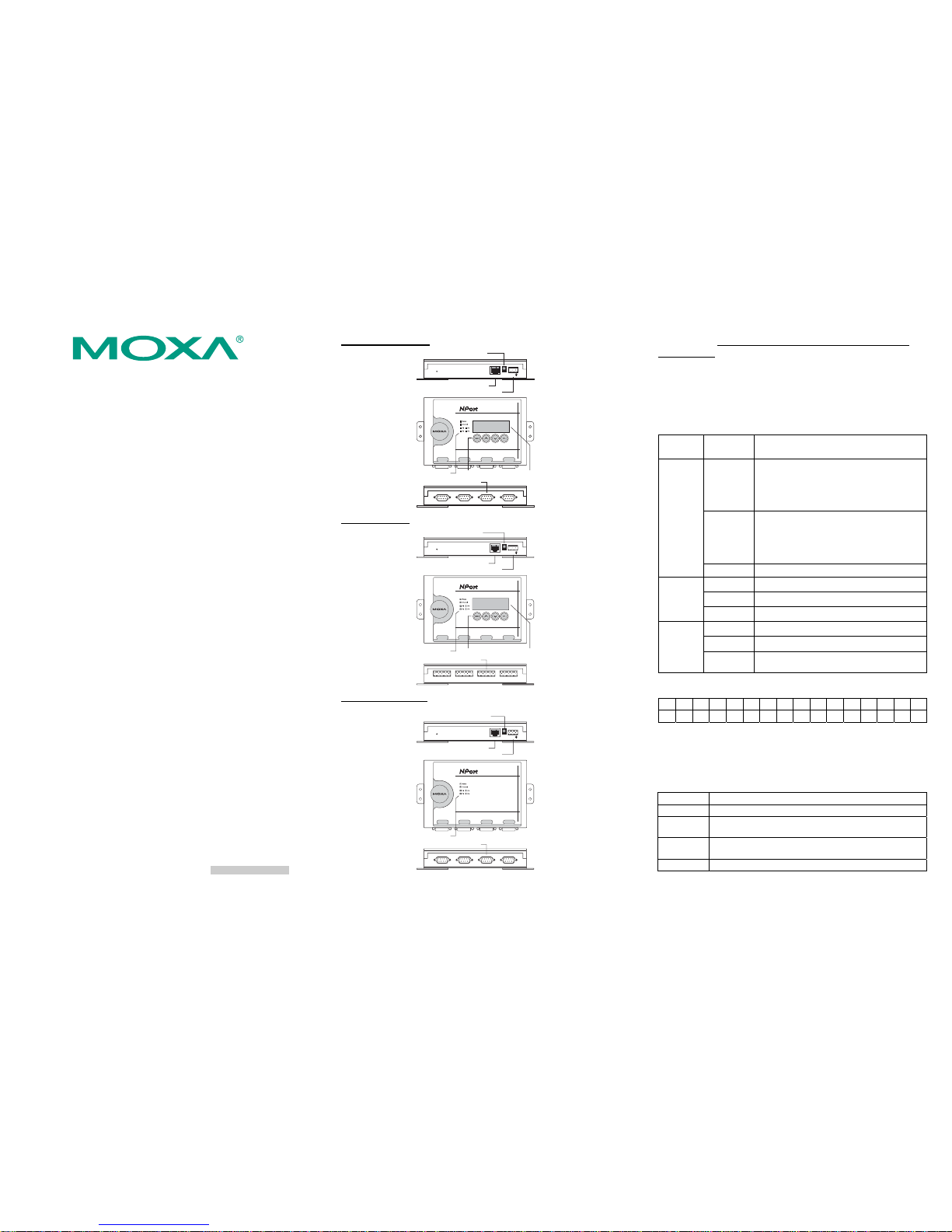
3. Hardware Introduction
As shown in the following figures, NPort 5410 has 4 Male DB9 ports, for
the RS-232 interface, NPort 5430/5430I has 4 5-pin terminal blocks, for
the RS-422/485 interface, and NPort 5450/5450I has 4 Male DB9 ports,
for the RS-232/422/485 interface.
NPort 5410/5450/5450I
RJ45 10/100 Mbps Ethernet port
Power Jack Power Input
Terminal Block power input
RESET
LCM display panelIndicator LEDs Input buttons
Male DB9 serial port
Serial Device Server
5410
NP5410_61405
192.168.127.254
LAN
V+V-
Port 1
RS-422/785
Port 2
RS-422/785
Port 3
RS-422/785
Port 4
RS-422/785
NPort 5430/5430I
RJ45 10/100 Mbps Ethernet port
TerminalBlock power input
RESET
LC
Power Jack Power Input
M display panelIndicator LEDs Input buttons
SerialDevice Server
5430
NP5410_61405
192.168.127.254
LAN
V+V-
RS-422/485 TerminalBlock
T+ T- R+D+R-D-GND T+ T- R+D+R-D-GND T+ T- R+D+R-D-GND T+ T- R+D+R-D-GND
Port1
RS-422/785
Port2
RS-422/785
Port3
RS-422/785
Port4
RS-422/785
NPort 5450-T/5450I-T
RJ45 10/100 Mbps Ethernet port
Terminal Block power input
RESET
Indicator LEDs
Power Jack Power Input
Male DB9 serial port
Serial Device Server
5450
LAN
V+V-
Port 1
RS-422/785
Port 2
RS-422/785
Port 3
RS-422/785
Port 4
RS-422/785
Reset Button—Press the Reset button continuously for 5 sec to load
factory defaults: Use a pointed object, such as a straightened paper clip or
toothpick, to press the reset button. This will cause the Ready LED to
blink on and off. The factory defaults will be loaded once the Ready LED
stops blinking (after about 5 seconds). At this point, you should release
the reset button.
LED Indicators—NPort 5400’s top panel contains six LED indicators, as
described in the following table.
LED
Name
LED Color LED Function
red
Steady on: Power is on and NPort is booting
up.
Blinking: Indicates an IP conflict, or
DHCP or BOOTP server did not
respond properly.
green
Steady on: Power is on and NPort is
functioning normally.
Blinking: The NPort has been located by
NPort Administrator’s Location
function
Ready
off
Power is off, or power error condition exists.
orange
10 Mbps Ethernet connection.
green
100 Mbps Ethernet connection.
Ethernet
off
Ethernet cable is disconnected, or has a short.
orange
Serial port is receiving data.
green
Serial port is transmitting data.
P1, P2, P3,
P4
off
No data is being transmitted or received
through the serial port.
LCM Display Panel (not support in -T model)—When the NPort 5400
unit is powered up, you will a see a display similar to:
NP5410_6140 5
1 9 2 . 1 6 8 . 1 2 7 . 2 5 4
This is where NP5410_61405 is the server’s name, and 192.168.127.254
is the server’s IP address.
LCM Panel Operation (not support in -T model)—There are four
buttons on NPort 5400’s top panel used to operate the server’s LCM
panel. Going from left to right, the buttons are:
Button
Action
MENU
Activates the main menu, or returns to a lower level.
^
Scrolls up through a list of items shown on the LCM
panel’s second line.
﹀
Scrolls down through a list of items shown on the LCM
panel’s second line.
SEL
Selects the option listed on the LCM panel’s second line.
P/N: 1802054000311
Page 2
— 4 — — 5 — — 6 —
Detailed LCM Panel Operating instructions can be found on the
CD-ROM in the “NPort 5400 Series User’s Manual.”
4. Hardware Installation Procedure
STEP 1: After removing NPort 5400 from the box, the first thing you
should do is attach the power adaptor.
STEP 2: Connect NPort 5400 to a network. Use a standard
straight-through Ethernet cable to connect to a Hub or Switch. When
setting up or testing NPort 5400, you might find it convenient to connect
directly to your computer’s Ethernet port. In this case, use a cross-over
Ethernet cable.
STEP 3: Connect NPort 5400’s serial port to a serial device.
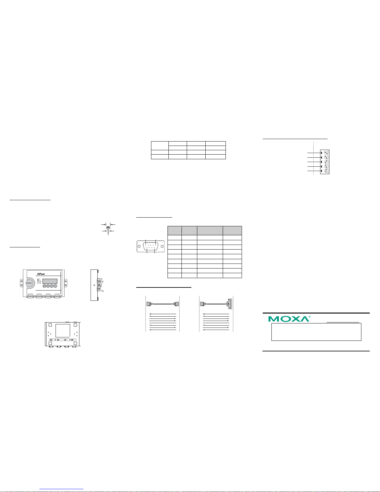
STEP 4: Placement Options
Wall or Cabinet Mounting
The NPort 5400 comes with two metal attachment plates for attaching the
NPort 5400 to a wall or the inside of a cabinet. First, use two screws per
bracket to attach the brackets to the rear of the NPort 5400. Next, use two
screws per bracket to attach the NPort 5400 to a wall or
cabinet.
The heads of the screws should be less than 6.0 mm in
diameter, and the shafts should be less than 3.5 mm in
diameter, as shown by the figure at the right.
DIN-Rail Mounting
DIN-rail attachments can be purchased separately to attach the product to
a DIN-rail. When snapping the attachments to the DIN-rail, make sure
that the stiff metal springs are at the top.
Wall Mount DIN-Rail
4 Port Device Server
5410
NP61405 SN:61405
192.168.127.254
Port 1
RS-422/785
Port 2
RS-422/785
Port 3
RS-422/785
Port 4
RS-422/785
5. Pull High/low Resistors Setting for the RS-485 Port
DIP switches on the bottom of NPort 5400 are used to set the pull
high/low resistor values for each serial port.
Pull High/low Resistors for the RS-485 Port
1 2 3
SW
Pull High Pull Low Terminator
ON 1KΩ 1KΩ 120Ω
Default
OFF 150KΩ 150KΩ ---
6. Software Installation Information
To install NPort Administration Suite, insert the NPort Document &
Software CD into your computer’s CD-ROM drive. Once the NPort
Installation CD window opens, click on the Installation button, and then
follow the instructions on the screen.
To view detailed information about NPort Administration Suite, click
on the Documents button, and then select “NPort 5400 Series User’s
Manual” to open the pdf version of this user’s guide.
7. Pin Assignments and Cable Wiring
DB9 Male Port Pinouts
Pin assignments apply to NPort 5410 (RS-232 only), 5450, and 5450I.
DB9 Male
15
69
Pin RS-232
RS-422/
4-wire RS-485
2-wire
RS-485
1 DCD TxD-(A) --2 RxD TxD+(B) --3 TxD RxD+(B) Data+(B)
4 DTR RxD-(A) Data-(A)
5 GND GND GND
6 DSR --- --7 RTS --- --8 CTS --- --9 --- --- ---
DB9 Wiring-NPort 5410/5450/5450I
DB9 Female to DB9 Male DB9 Female to DB25 Male
NPort
Signal Signal
DCD
RxD
TxD
DTR
GND
DSR
RTS
CTS
DCD
TxD
RxD
DSR
GND
DTR
CTS
RTS
RS-232
Device
g
niriW elbaC
1
2
3
4
5
6
7
8
1
2
3
4
5
6
7
8
DB9 Male DB9 Female
DB9
Male
DB9
Female
NPort
Signal Signal
DCD
RxD
TxD
DTR
GND
DSR
RTS
CTS
DCD
TxD
RxD
DSR
GND
DTR
CTS
RTS
RS-232
Device
g
niriW elbaC
1
2
3
4
5
6
7
8
8
3
2
20
7
6
4
5
DB25 Male DB9 Female
DB9
Male
DB25
Female
Terminal Block Wiring- NPort 5430/5430I
Rx+
GND
Rx
-
Tx+ / Data+
Tx
-
/ Data
-
T+
GND
T
-
R+ / D+
R
-
/ D
-
Serial Device
Signals
NPort 5430/5430I
Terminal Block
8. Environmental Specifications
Power requirements
Input Voltage: 12 to 48VDC
Power Consumption:
NPort 5410
350 mA @ 12 V, 190 mA @ 24 V
NPort 5430
320 mA @ 12 V, 175 mA @ 24 V
NPort 5430I
530 mA @ 12 V, 280 mA @ 24 V
NPort 5450
350 mA @ 12 V, 190 mA @ 24 V
NPort 5450I
554 mA @ 12 V, 294 mA @ 24 V
Operating temp.
Standard Models:
0 to 55°C (32 to 131°F)
Wide Temp. Models:
-40 to 75°C (-40 to 167°F)
Operating humidity 5 to 95% RH
Dimensions (W×D×H) 158 × 33 × 103 mm
6.22 × 1.3 × 4.06 in
Serial line protection 15 KV ESD for serial port, 2 KV
isolation protection (NPort 5430I/5450I)
Magnetic isolation 1.5 KV for Ethernet
Power line protection Level 2 Burst (EFT), EN61000-4-4
Level 2 Surge, EN61000-4-5
Regulatory approvals FCC Class A, CE Class A, UL, DNV,
LVD, TÜV
Click here for online support:
www.moxa.com/support
The Americas: +1-714-528-6777 (toll-free: 1-888-669-2872)
Europe: +49-89-3 70 03 99-0
Asia-Pacific: +886-2-8919-1230
China: +86-21-5258-9955 (toll-free: 800-820-5036)
© 2009 Moxa Inc. All rights reserved.
Reproduction without permission is prohibited.
6.0 mm
3.5 mm
 Loading...