

Moxa Technologies NPort 5150AI-M12-T, NPort 5150AI-M12-CT, NPort 5250AI-M12, NPort 5250AI-M12-CT, NPort 5250AI-M12-T User Manual
...Page 1

NPort 5x50AI-M12 Series User Manual
First Edition, June 2012
www.moxa.com/product
© 2012 Moxa Inc. All rights reserved.
Reproduction without permission is prohibited.
Page 2

NPort 5x50AI-M12 Series User’s Manual
Moxa Americas
Toll
Tel:
Fax:
Moxa China (Shanghai office)
Toll
Tel:
Fax:
Moxa Europe
Tel:
Fax:
Moxa Asia
Tel:
Fax:
The software described in this manual is furnished under a license agreement and may be used only in accordance with
the terms of that agreement.
Copyright Notice
Copyright ©2012
Moxa Inc.
All rights reserved.
Reproduction without permission is prohibited.
Trademarks
The MOXA logo is a registered trademark of Moxa Inc.
All other trademarks or registered marks in this manual belong to their res pec tive manufacturers.
Disclaimer
Information in this document is subject to cha nge witho ut no ti c e and doe s not repres e nt a co mmitment o n the part of
Moxa.
Moxa provides this document as is, without warranty of any kind, either expressed or implied, including, but not limited
to, its particular purpose. Moxa reserves the rig ht to make improvements and/or changes to this manual, or to the
products and/or the programs described in this manual, a t any time .
Information provided in this manual is intended to be accurate and reliable. However, Moxa assumes no responsibility for
its use, or for any infringements on the rights of third parties that m ay res ult fr om its use.
This product might include unintentional tec hnic a l o r typographical errors. Changes are periodically made to the
information herein to correct such errors, and these changes are incorporated into new editions of the publica tio n.
Technical Support Contact Information
www.moxa.com/support
-free: 1-888-669-2872
+1-714-528-6777
+1-714-528-6778
+49-89-3 70 03 99-0
+49-89-3 70 03 99-99
-free: 800-820-5036
+86-21-5258-9955
+86-10-6872-3958
+886-2-8919-1230
-Pacific
+886-2-8919-1231
Page 3

Table of Contents
1. Introduction ...................................................................................................................................... 1-1
Overview ........................................................................................................................................... 1-2
Package Checklist ............................................................................................................................... 1-2
Product Features ................................................................................................................................ 1-2
Product Specifications ......................................................................................................................... 1-2
2. Getting Star ted.................................................................................................................................. 2-1
NPort 5x50A I-M 1 2 Se ries Appearance ................................................................................................... 2-1
Connecting the Hardware..................................................................................................................... 2-1
Wiring Requirements ................................................................................................................... 2-1
Connecting the Power .................................................................................................................. 2-2
Connecting to the Network ........................................................................................................... 2-2
Connecting to a Serial Device ....................................................................................................... 2-2
LED Indicators ............................................................................................................................ 2-2
3. Initial IP Address Configuration ........................................................................................................ 3-1
Initializing the NPort’s IP Address ......................................................................................................... 3-2
Factory Default IP Address ................................................................................................................... 3-2
NPort Administration Suite ................................................................................................................... 3-2
ARP................................................................................................................................................... 3-2
Telnet Console ................................................................................................................................... 3-3
Serial Console (19200, n, 8, 1) ............................................................................................................. 3-6
4. Choosing the Proper Operation Mode ................................................................................................ 4-1
Overview ........................................................................................................................................... 4-2
Real COM Mode .................................................................................................................................. 4-2
RFC2217 Mode ................................................................................................................................... 4-3
TCP Server Mode ................................................................................................................................ 4-3
TCP Client Mode ................................................................................................................................. 4-3
UDP Mode .......................................................................................................................................... 4-4
Pair Connection Mode .......................................................................................................................... 4-4
Ethernet Modem Mode ......................................................................................................................... 4-4
Reverse Telnet Mode ........................................................................................................................... 4-5
Disabled Mode .................................................................................................................................... 4-5
5. Web Console Configuration ............................................................................................................... 5-1
Opening Your Browser ......................................................................................................................... 5-2
Quick Setup ....................................................................................................................................... 5-3
Export/Import .................................................................................................................................... 5-6
Basic Settings .................................................................................................................................... 5-6
Network Settings ................................................................................................................................ 5-7
Serial Settings .................................................................................................................................. 5-10
Operating Settings ............................................................................................................................ 5-12
Real COM Mode ......................................................................................................................... 5-12
RFC2217 Mode .......................................................................................................................... 5-15
TCP Server Mode ....................................................................................................................... 5-17
TCP Client Mode ........................................................................................................................ 5-20
UDP Mode ................................................................................................................................ 5-24
Pair Connection Mode ................................................................................................................ 5-26
Ethernet Modem Mode ............................................................................................................... 5-28
Reverse Telnet Mode ................................................................................................................. 5-30
Disabled Mode .......................................................................................................................... 5-31
Accessible IP Settings........................................................................................................................ 5-32
Auto Warning Settings ....................................................................................................................... 5-33
Auto warning: Email and SNMP trap ............................................................................................ 5-33
Event Type ............................................................................................................................... 5-34
Upgrade Firmware ............................................................................................................................ 5-36
Monitor............................................................................................................................................ 5-36
Monitor Line ............................................................................................................................. 5-36
Monitor Async ........................................................................................................................... 5-37
Monitor Async-Settings .............................................................................................................. 5-37
Monitor Relay Output ................................................................................................................. 5-38
Change Password ............................................................................................................................. 5-38
Load Factory Default ......................................................................................................................... 5-39
Save/Restart .................................................................................................................................... 5-39
6. Configuring NPort Administrator ....................................................................................................... 6-1
Overview ........................................................................................................................................... 6-2
Installing NPort Administrator .............................................................................................................. 6-2
Configuration ..................................................................................................................................... 6-4
Broadcast Search ........................................................................................................................ 6-5
Page 4

Unlock Password Protection .......................................................................................................... 6-6
Configuring the NPort 5x50AI-M12 ................................................................................................ 6-7
Upgrading the Firmware ............................................................................................................... 6-9
Export Configuration .................................................................................................................. 6-10
Import Configuration ................................................................................................................. 6-10
Monitor............................................................................................................................................ 6-11
Port Monitor ..................................................................................................................................... 6-15
COM Mapping ................................................................................................................................... 6-15
On-line COM Mapping ................................................................................................................ 6-16
Off-line COM Mapping ................................................................................................................ 6-19
COM Grouping .................................................................................................................................. 6-20
Creating a COM Group ............................................................................................................... 6-20
Deleting a COM Group................................................................................................................ 6-22
Adding a Port to a COM Group .................................................................................................... 6-24
Removing a Port from a COM Group ............................................................................................ 6-25
Modify Ports in a COM Group ...................................................................................................... 6-27
Changing the COM Number of a COM Group ................................................................................. 6-27
Changing Advanced Settings and Serial Par ameters of the COM Group ............................................. 6-29
Changing the Serial Port Specified as Signal Por t for the COM Group ............................................... 6-31
IP Address Rep ort ............................................................................................................................. 6-32
7. IP Serial LIB ...................................................................................................................................... 7-1
Overview ........................................................................................................................................... 7-2
IP Serial LIB Function Groups ............................................................................................................... 7-3
Example Program ............................................................................................................................... 7-3
A. Pinouts and Cable Wiring .................................................................................................................. A-1
Pin Assignments and Cable Wiring ........................................................................................................ A-2
Ethernet M12 .............................................................................................................................. A-2
Power M12 ................................................................................................................................. A-2
RS-232/422/485 (male DB9) Pinouts ............................................................................................. A-2
Serial Cable Wiring Diagrams ............................................................................................................... A-3
Female DB9 to Male DB9 .............................................................................................................. A-3
B. Well Known Port Numbers ................................................................................................................ B-1
C. SNMP Agents with MIB II & RS-232 Like Groups .............................................................................. C-1
D. Auto IP Report Protocol .................................................................................................................... D-1
E. Compliance Notice ............................................................................................................................. E-1
Page 5

1
1. Introduction
Welcome to the NPort IA5400A Series of industrial ser i al devic e serv ers . In this manual, w e refer to the four
products in the series collectively as “N Por t 5x50AI-M12 Series.”
The nine models in the NPort 5x50AI-M12 Series are:
NPort 5150AI-M12 1-port RS-232/422/485 Device Server , 1 x 10/10 0BaseT(X) with M12
Connector, M12 Power Input, -25 to 55°C
NPort 5150AI-M12-CT 1-port RS-232/422/485 Device Server , 1 x 10/10 0BaseT(X) with M12
Connector, M12 Power Input, -25 to 55°C, Conformal Coating
NPort 5150AI-M12-T 1-port RS-232/422/485 Device Server , 1 x 10/10 0BaseT(X) with M12
Connector, M12 Power Input, -40 to 70°C
NPort 5250AI-M12 2-port RS-232/422/485 Device Server , 1 x 10/100BaseT(X) with M12
Connector, M12 Power Input, -25 to 55°C
NPort 5250AI-M12-CT 2-port RS-232/422/485 Device Server , 1 x 10/10 0BaseT(X) with M12
Connector, M12 Power Input, -25 to 55°C, Conformal Coating
NPort 5250AI-M12-T 2-port RS-232/422/485 Device Server , 1 x 10/10 0BaseT(X) with M12
Connector, M12 Power Input, -40 to 70°C
NPort 5450AI-M12 4-port RS-232/422/485 Device Server , 1 x 10/100BaseT(X) with M12
Connector, M12 Power Input, -25 to 55°C
NPort 5450AI-M12-CT 4-port RS-232/422/485 Device Server , 1 x 10/10 0BaseT(X) with M12
Connector, M12 Power Input, -25 to 55°C, Conformal Coating
NPort 5450AI-M12-T 4-port RS-232/422/485 Device Server , 1 x 10/10 0BaseT(X) with M12
Connector, M12 Power Input, -40 to 70°C
The following topics are covered in this chapter:
Overview
Package Checklist
Product Features
Product Specifications
Page 6

NPort 5x50AI-M12 Series Introduction
1-2
Ethernet Interface
Number of Ports: 1
Speed:
Connector:
Serial Interface
Number of Ports:
Serial Standards:
Connector:
Serial Line Protection:
RS
Serial Communicat ion Parameters
Data Bits:
Overview
NPort 5x50A I-M 1 2 de vice server is designed to make serial devices network-ready in an instant and is
compliant with EN 50155 and EN 50121-4 standards, allowing them to perform reliab ly in rolling stock and
wayside applications where high level vibr ation is present. Use the NPort 5x50AI-M12 device ser ve rs to give
your PC software direct access to serial dev ic e s from anyw here on the netwo rk .
Package Checklist
Before installing the NPort 5x50AI-M12 series device servers, verify that the package contains the following
items:
Standard Accessories
• 1 NPort 5x50AI-M12 serial device server
• Wall Mount Kit
• Documentation and Software CD
• Quick Installation Guide (printed )
• Warranty Card
Optional Accessories
• DR-4524 45W/ 2A DIN-Rail 24 VDC Power Supply with universal 85 to 264 VAC input
• DR-75-24 75W/3.2A DIN-Rail 24 VDC Power Supply with universal 85 to 264 VAC input
• DR-120-24 120W/5A DIN-Rail 24 VDC Power Supply with 88 to 132 VAC/176 to 264 VAC input by switch
• WK-36-01 Wall mounting kit
NOTE: Notify your sales representative if any of the above items is missing or damaged.
Product Features
The NPort 5x50AI-M12 Series are the world’s first EN 50155 compliant device servers and have the following
features:
• Versatile socket operation modes , inc luding TCP Server, TCP Client, UDP
• Support UDP multicast and COM Grouping
• -40 to 70°C operating temperature range (T models only)
• Compliant with EN 50155/50121-4
• M12 connector and IP40 metal housing
• 2 KV isolation for serial signals
Product Specifications
10/100 Mbps, auto MDI/M DIX
M12
DB9 male
-485 Data Direction Control: ADDC® (automatic data direction control)
5, 6, 7, 8
1/2/4
RS-232/422/485
15 KV ESD protection for all signals
Page 7

NPort 5x50AI-M12 Series Introduction
1-3
Stop Bits:
Parity:
Flow Control:
Baudrate:
Serial Signals
RS
RS-422: Tx+, Tx-, Rx+ , Rx-, GND
RS
RS
Software
Network Protocols:
LLDP Configuration Options:
Windows Real COM Drivers:
Fixed TTY Drivers:
Solaris 10, Fr
Linux Real TTY Drivers:
Physical Characteristics
Housing:
Weight:
Dimensions:
Environmental Limits
Operating Temperatur e:
Standard Models:
Wide Temp. Models:
Ambient Relative
Storage Temperature:
Power Requirements
Input Voltage:
Power Consumption: 439.4 mA@12V
Connector:
Standards and Certifications
EMI
Safety:
EMC:
EMS:
Rail
Reliability
Alert Tools:
Automatic Reboot Trigger:
Warranty
Warranty Period:
Details:
1, 1.5, 2
None, Even, Odd, Space, Mark
RTS/CTS and DTR/DSR (RS-232 only), XON/XOFF
50 to 921.6 Kbps
-232: TxD, RxD, RTS, CTS, DTR, DSR, DCD, GND
-485-4w: Tx+ , Tx-, Rx+, Rx-, GND
-485-2w: Data+, Data-, GND
ICMP, IP, TCP, UDP, DHCP, BOOTP, Telnet, DNS, SNMP V1, HTTP, SMTP, IGMP V1/2,
Web Console (with new Quick Setup), Telnet Console, Windo ws Utility
Windows 98/ME/NT/2000, Windows XP/2003 /Vista/2008/7 x86/x64
SCO Unix, SCO OpenServer, UnixWare 7, UnixWare 2.1, SVR 4.2, QNX 4.25, QNX 6,
eeBSD, AIX 5.x, HP-UX 11i, Mac 10.3
Linux kernel 2.4.x, 2.6.x, 3.0.x
Metal
0.56 kg (1.23 lb)
80 x 216.6 x 52.9 mm (3.15 x 8.53 x 2.08 in)
-25 to 55°C (-13 to 131°F)
-40 to 75°C (-40 to 167°F) EN 50155 Compliant
Humidity: 5 to 95% (non-condensing)
-40 to 85°C ( -40 to 185°F) EN 50155 Compliant
12 to 48 VDC
M12
: EN 55022 Class A, FCC Part 15 Subpart B Class A
UL 60950-1, EN 60950-1
EC, FCC
EN 55024
Traffic: EN 50155, EN 50121-4
Built-in buzzer and R TC
Built-in WDT (watchdog timer)
5 years
See www.moxa.com/warranty
Page 8

2
2. Getting Started
In this chapter, we give instructions o n installing NPort 5x50AI-M12 device servers. Software installation is
covered in subsequent chapters.
The following topics are covered in this chapte r:
Page 9
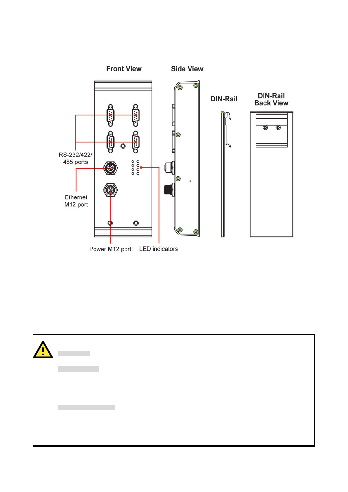
NPort 5x50AI-M12 Series App earance
ATTENTION
Safety First!
Be sure to disconnect the power cord before installing and /or wir ing your NPort
Wiring Caution!
Calculate the maximum possible curre nt in each power wire and com mon wire . Observe all elec trical codes
dictating the maximum current allowab
If the current goes above the maximum ratings, the wiring could overheat, causing serious damage to your
equipment.
Temperature Caution!
Please take care when handling NPort
components generate heat, and consequently the casing may feel hot to the touch. When installed with other
components, make sure that there is at least 2 cm clearance on all sides of NPort
in order to allow
proper heat dissipation.
Connecting the Hardware
This section describes how to connect NPort 5x50AI-M12 to serial devices for first tim e testing p urposes. We
cover Wiring Requirements, Connecting the Power, Connecting to the Network, Connecting to a
Serial Device, and LED Indicators.
Wiring Requirements
5x50AI-M12 Series.
le for each wire size.
5x50AI-M12. When plugged in, NPort 5x50AI-M12’s internal
5x50AI-M12
Page 10

NPort 5x50AI-M12 Series Getting Started
2-2
You should observe the following:
• Use separate paths to route wiring for power and devices . If power wir ing and devic e wir ing pa ths must
cross, make sure the wires are perpendicular at the intersection point.
NOTE: Do not run s ignal or commu nication wiri ng and power wiring in t he same wir e conduit. T o
avoid interfer enc e , wires wi th di ff e re nt signal character istics should be routed sep ara te l y.
• You can use the type of signal transmitted through a wire to determine which wires should be kept separate.
The rule of thumb is that wiring that shares similar electrical characteristics can be bundled together.
• Keep input wiring and output wiring separate.
• Where necessary, it is strongly advised that you labe l wir ing to all devices in the system.
Connecting the Power
Connect the power line with the NPort 5x50AI-M12’s M12 connector. If the power is properly supplied, the
“Ready” LED will show a solid red color until the system is ready, at which time the “Ready” LED will change to
a green color.
Connecting to the Network
Connect one end of the Ethernet cable to the NPort 5x50AI-M12’s 10/100M Ethernet port and the other end of
the cable to the Ethernet network. If the cable is properly connected, the NPort 5x50AI-M12 will indicate a valid
connection to the Ethernet in the following ways:
• The Ethernet LED maintains a solid green color when connecte d to a 100 Mbps Etherne t network.
• The Ethernet LED maintains a solid orange color when connected to a 10 Mbps Ethernet network.
• The Ethernet LED will flash when Ethernet packets are being transmitted or received.
Connecting to a Serial Device
Connect the serial data cable between NPort 5x50AI-M12 and the serial device. Serial data cables are optional
accessories for NPort.
LED Indicators
The top panels of all NPort 5x50AI-M12 have four LED indicators , as descr ib ed in the followi ng table.
Name Color Function
PWR green Power from Power 1 input
Steady on: Power is on and NPort is booting up.
red
Blinking: Indicates an IP conflict, or DHCP/BOOTP server did not respond properly.
Ready
10M,
100M
P1, P2,
P3, P4
green
orange 10 Mbps Etherne t connection.
green 100 Mbps Etherne t connection.
orange Se rial port is receiving data.
green Ser ial port is tra ns mitting data.
Steady on: Power is on and NPort is functioning normally.
Blinking: The NPort has been located by NPort Administrator’s Location function.
off Power is off, or a power error condition exists.
off Ethernet cable is disconnected, or has a short.
off No data is being transmitted or received through the s erial port.
Page 11

3
3. Initial IP Address Configuration
When setting up your NPort 5x50AI-M12 for the fir s t time , the f irst thing you should do is configure the IP
address. This chapter introduces the metho ds that c an be used to conf igure the device server’s IP address.
Select one of the initial IP Address configuration methods to configure NP ort 5x50AI-M12’s IP
Address. For more details about network settings, see the Network Settings section from Chapter 5, Web
Console Configuration.
The following topics are covered in this chapter:
Initializing the NPort’s IP Address
Factory Default IP Address
NPort Administration Suite
ARP
Telnet Console
Serial Console (19200, n, 8, 1)
Page 12

NPort 5x50AI-M12 Series Initial IP Addre ss Configuration
3-2
ATTENTION
Consult your network administrato r o n how to reserv e a fixed I P address for your NPort
in the
MAC-IP mapping table when using a DHCP Server or BOOTP Server. In most applications, you should assign
a fixed IP address to your NPort
ATTENTION
In order to use this setup method, both your computer and NPort
connected to the sam e
LAN. Or, you may use a cross
computer’s Ethernet card. Before exec uting the AR P command,
must be configured
with the factory default IP address
must
be on the same subnet.
Initializing the NPort’s IP Address
1. Determine whether your NPort 5x50AI-M12 needs to use a Static IP or Dynamic IP (either DHCP or BOOTP
application).
2. If the NPort 5x50AI-M12 is used in a Static IP environment, you can use NPort Administration Suite,
ARP, Web Console, Telnet Console, or Serial Console to conf igur e the new IP address.
3. If the NPort 5x50AI-M12 is used in a Dynamic IP environment, you can use NPort 5x50AI-M12
Administration Suite, Web Console, Telnet Console, or Serial Console to configure NPort 5x50AI-M12 to get
an IP address dynamically with DHCP, DHCP/BOOTP, or BOOTP.
5x50AI-M12.
Factory Default IP Address
NPort 5x50AI-M12 products are configured with the following default private IP address:
Default IP address: 192.168.127.254
(IP addresses of the form 192.168.xxx.xxx are referr ed to as priv ate IP addre s s es, si nc e it is not possible to
directly access a device configured with a private IP address from a public network. For example, you would not
be able to ping such a device from an outside Internet connection. NPort 5x50AI-M12 applications that require
sending data over a public network, such as the Internet, require setting up the serv er with a va lid p ublic IP
address, which can be leased from a local ISP.)
NPort Administration Suite
NPort Administration Suite consists of some useful utility programs that are used to configure and manage your
NPort 5x50AI-M12.
See Chapter 5 for de tails o n ho w to i ns tall NP ort A dm inistr atio n Sui te, and how to use thi s s uite o f
useful utilities to se t up IP add re s se s and conf i g ure your NPo rt 5x50AI-M12 Series serial device
servers.
5x50AI-M12
ARP
You can make use of the ARP (Addres s Resolutio n Protocol) command to set up an IP address for your NPort
5x50AI-M12. The ARP command tells your computer to associate the NPort 5x50AI-M12’s MAC address with
the intended IP address. You must then use Telnet to access the NPort 5x50AI-M12, at which point the device
server’s IP address will be reconfigured.
-over Ethernet cable to connect the NPort 5x50AI-M12 directly to your
(192.168.127.254), and your computer and the NPort 5x50AI-M12
5x50AI-M12 must be
your NPort 5x50AI-M12
Page 13
NPort 5x50AI-M12 Series Initial IP Addre ss Configuration
3-3
ATTENTION
Figures in this chapter were generated using
Take the following steps to use ARP to configure the IP address:
1. Obtain a valid IP address for your NPort 5x50AI-M12 from your network administrator.
2. Obtain the NPort 5x50AI-M12’s MAC address from the label on its bottom panel.
3. Execute the ‘arp -s’ command from your computer’s MS-DOS prompt by typing :
arp –s 192.168.200.100 00-90-E8-xx-xx-xx
This is where 192.168.200.100 is the new IP address and 00-90-E8-xx-xx-xx is the MAC address for your
NPort 5x50AI-M12. (Be sure to use the actual IP address and MAC address for your NPort 5x50AI-M12.)
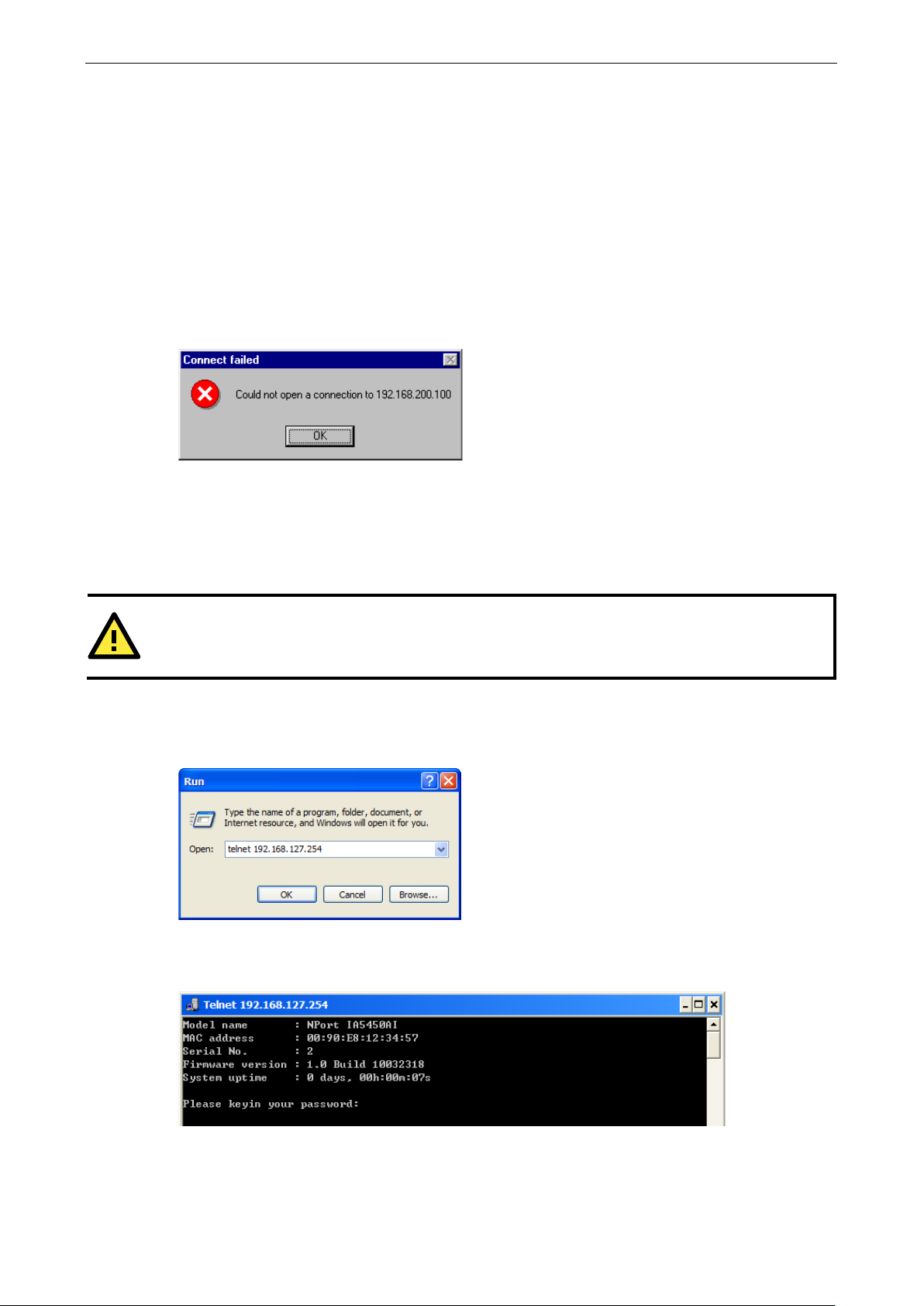
4. Next, execute a special Telne t c omma nd by typing :
telnet 192.168.200.100 6000
After issuing this command, a Connect failed message will appear, as shown here. After the NPort reboots,
its IP address should be updated to the new address, and you can reconnect us ing either Telnet, Web, or
Administrator to check that the update was succe ssf ul.
Telnet Console
Depending on how your computer and network are configured, you may find it convenient to use network
access to set up your NPort 5x50AI-M12’s IP address. This can be done using Telnet.
1. From the Windows desktop , click on Start and then select Run.
2. Type telnet 192.168.127.254 (use the correct IP addre s s if different fr om the default) in the Open text
input box, and then click OK.
3. When the Telnet window opens, if you are prompted to input the Console password, input the password and
then press Enter.
Note that this page will only appear if the NPort is password pro te c ted .
the NPort 5x50AI-M12I.
Page 14
NPort 5x50AI-M12 Series Initial IP Addre ss Configuration
3-4
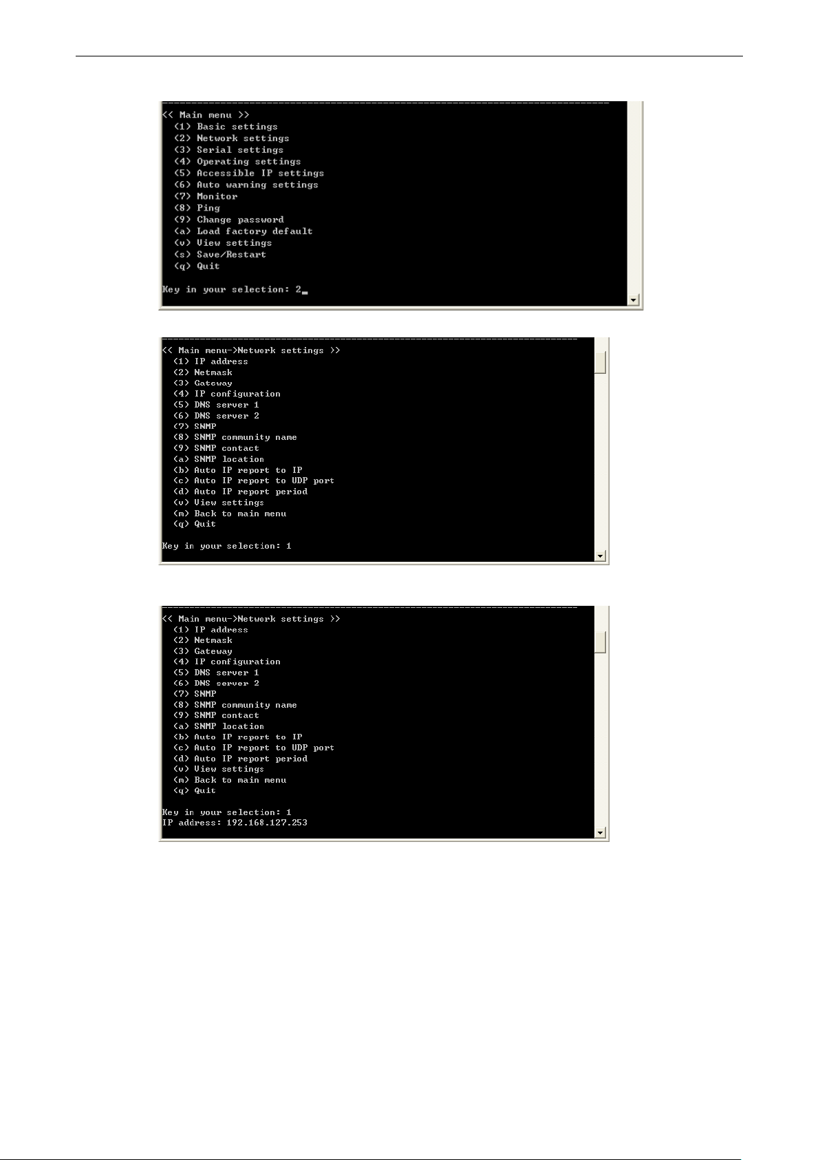
4. Type 2 to select Network setting s , a nd then pr e ss Enter.
5. Type 1 to select IP address and then press Enter.
6. Use the Backspace key to erase the current IP address, type in the new IP address, and then press
Enter.
Page 15
NPort 5x50AI-M12 Series Initial IP Addre ss Configuration
3-5
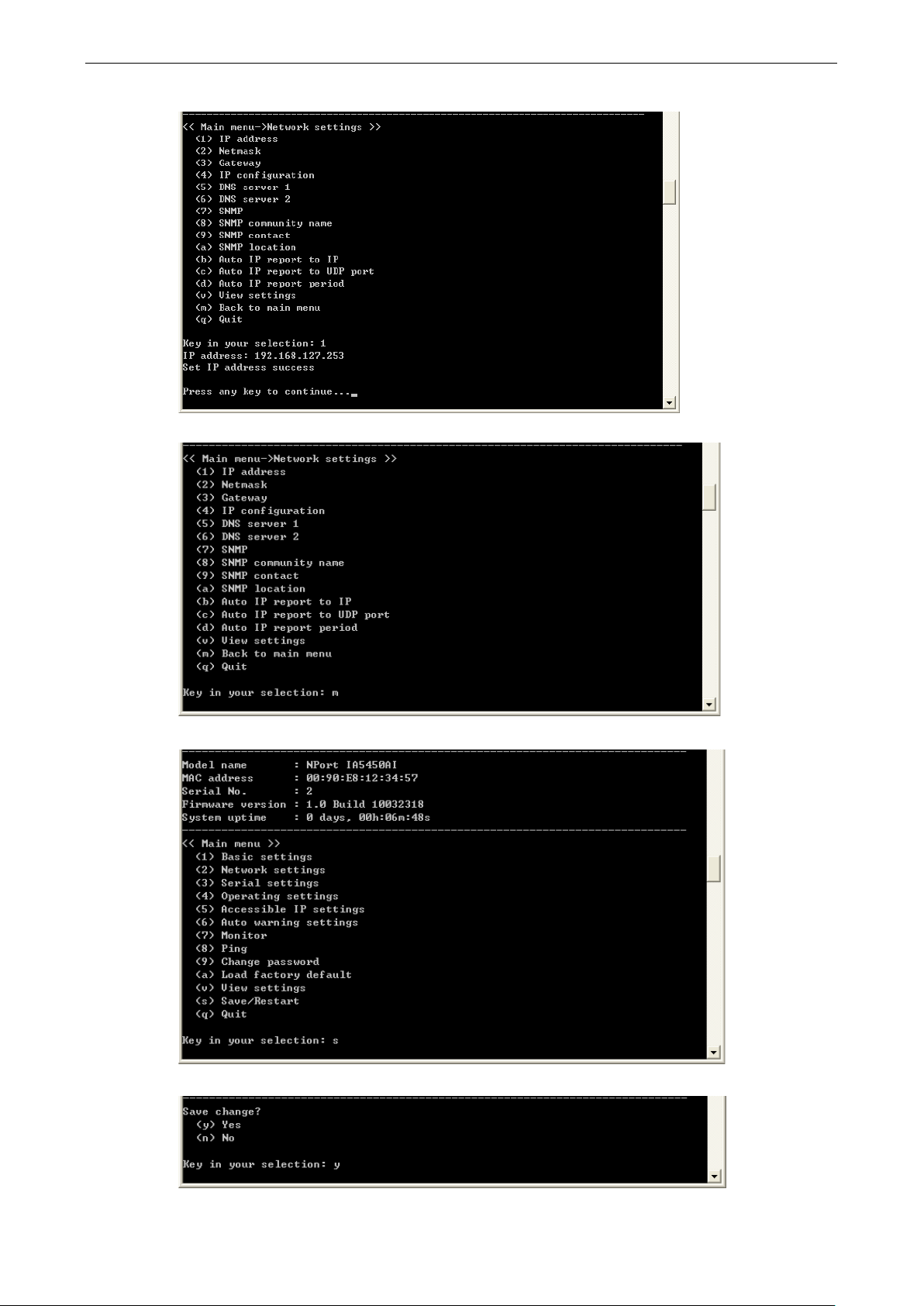
7. Press any key to continue…
8. Type m and then press Enter to return to the main menu.
9. Type s and then press Enter to Save/Restart the system.
10. Type y and then press Enter to save the new IP address and restar t the NPort 5x50AI-M12.
Page 16
NPort 5x50AI-M12 Series Initial IP Addre ss Configuration
3-6
ATTENTION
The
Serial Console (19200, n , 8, 1)
You may use the RS-232 console port to set up the IP address for NPort 5x50AI-M12. We sug gest using PComm
Terminal Emulator, which is available free of charge as part of the PComm Lite program suite, to carry out the
installation procedure , althoug h other similar utilities may also be used.
Serial Console is at serial port 1 of the NPort 5x50AI-M12 Series, with RS-232 mode.
Before you start to configure the NPort 5x50AI-M12 via serial console, turn off the power and connect the serial
cable from NPort 5x50AI-M12 to your computer’s serial port.
1. Connect NPort 5x50AI-M12’s serial port 1 directly to your computer’s male RS -232 serial port.
2. From the Windows desktop clic k on Start Programs PComm Lite Terminal Emulator.
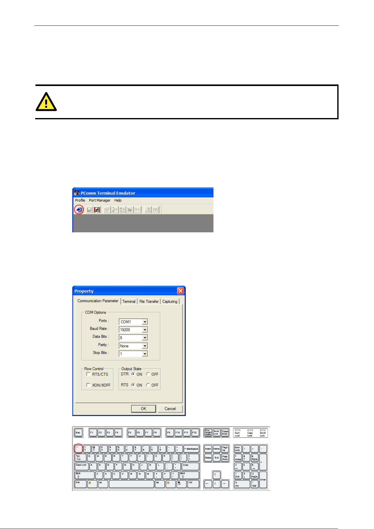
3. When the PComm Terminal Emulator window opens, first click on the Port Manager menu item and select
Open, or simply click on the Open icon.
4. The Property window ope ns automatic al ly . From the Communication Parameter page, select the
appropriate COM port for the connection, COM1 in this example, and 19200 for Baud Rate, 8 for Data Bits,
None for Parity, and 1 for Stop Bits.
5. From the Property window’s Terminal page, select ANSI or VT100 for Terminal Type and then click OK.
Note: If you select Dumb Terminal as the terminal type, some of the conso l e functio ns —especially the
“Monitor” function—may n ot work properly .
6. Press the “ ` ” key continuously and then po wer o n the NPort 5x50AI-M12.
Page 17
NPort 5x50AI-M12 Series Initial IP Addre ss Configuration
3-7
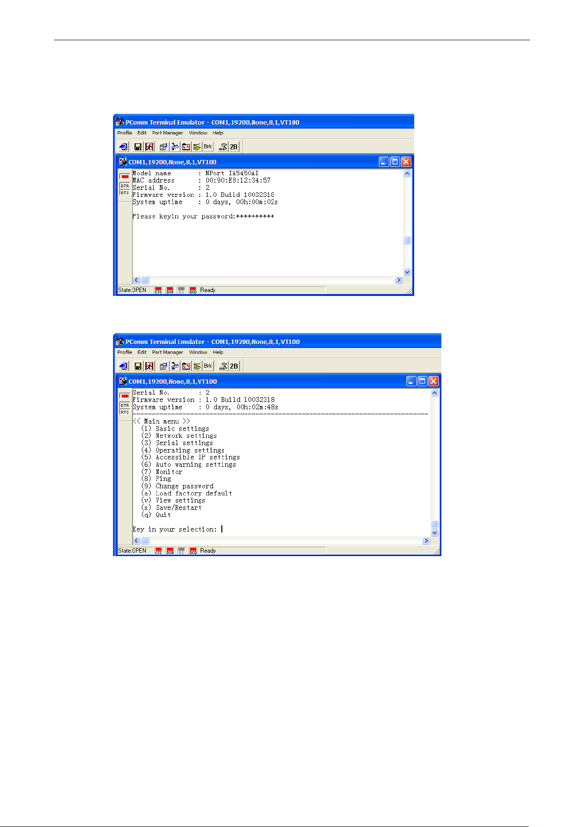
7. The NPort 5x50AI-M12 will automatically switc h fro m data mod e to conso le mode as it receives a
continuous string of “ ` ” characters.
8. Input the password when prompted. Note that this page will only appear when the NPort 5x50AI-M12 has
been set up for password protection.
9. Start configuring the I P address under Netwo rk Setting s . Refe r to step 4 in the Telne t Console section for
the rest of the IP settings.
Page 18

4
4. Choosing the Proper Operation Mode
In this chapter, we describe the various NPort 5x50AI-M12 operation modes. The options include an operation
mode that uses a driver installed on the host computer, a nd operati o n modes that rely on TCP/I P so cke t
programming concepts. Af ter choosing the proper operation mode in this chapter, refer to Chap ter 5 for
detailed configuration parameter definitions.
The following topics are covered in this chapter:
Overview
Real COM Mode
RFC2217 Mode
TCP Server Mode
TCP Client Mode
UDP Mode
Pair Connection Mode
Ethernet Modem Mode
Reverse Telnet Mode
Disabled Mode
Page 19
NPort 5x50AI-M12 Series Choosing the Proper Operation Mo de
4-2
NPort
work with
95/98/ME/NT/2000/XP//2003/Vista/2
x64/2003 x64/Vista x64/2008 x64/7 x64
also TTY
establishes a
serial
5x50AI
host computer. Real COM Mode also
simultaneous connections, so that
collect data from the same
ATTENTION
The driver used for Real COM Mode comes with the NPort Administrator. The driver is installed automatically
on your computer when you install NPort Administr a tio n Suite.
Overview
NPort 5x50AI-M12 Serial Device Server s network-enable traditional RS-232/422/485 devices, in which a Serial
Device Server is a tiny computer equipped with a CPU, real-time O S , and TCP/IP protocols that can
bi-directionally translate data betwee n the seria l and Ethernet formats. Your computer can access, manage,
and configure remote facilities and equipment over the Internet from anywhere in the world.
Traditional SCADA and data collection sy s te ms rely on serial ports (RS-232/422/485) to collect data from
various kinds of instruments. Since NPor t 5x50AI-M12 Serial Device Servers network-enable ins truments
equipped with an RS-232/422/485 communication port, your SCADA and data collection system will be able to
access all instruments connected to a standard TCP/IP network, regardless of whether the devices are used
locally or at a remote site.
NPort 5x50AI-M12 is an external IP-based network device that allows you to expand the number of serial ports
for a host computer on demand. As long as your host computer s upports the TCP/IP protocol, you won’t be
limited by the host computer’s bus limitation (suc h as ISA or PCI), or lack of drivers for various operating
systems.
In addition to providing socket access, NPort 5x50AI-M12 also comes with a Real COM/TTY driver that
transmits all serial signals intact. This me a ns that your existing COM/TTY-based softwar e ca n be preserv ed,
without needing to invest in additional s of tware.
Three different Socket Modes are available : TCP Server, TCP Client, and UDP Server/Client. The main
difference between the TCP and UDP protocols is that TCP guarantees delivery of data by requiring the recipient
to send an acknowledgement to the sender. UDP does not require this type of verification, making it possible
to offer speedier delivery. UDP also allows unicast or multicast of data to only one IP or groups of IP addres ses.
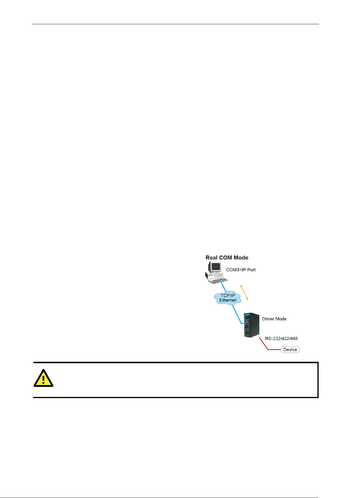
Real COM Mode
5x50AI-M12 comes equipped with COM drivers that
Windows
drivers for Linux or Unix systems. The driver
transparent connection between host a nd
device by mapping the IP:Port of the NPort
-M12’s serial port to a local COM/TTY port on the
serial device at the same time.
008/7/XP
systems, and
suppo rts up to 8
multiple hosts can
One of the major conveniences of using Real COM Mode is that Real COM Mode allows users to continue using
RS-232/422/485 serial communications software that was written for pure serial communications applications.
The driver intercepts data sent to the host’s COM port, packs it into a TCP/IP packet, and then redirects it
through the host’s Ethernet card. At the other end of the connection, the NPort 5x50AI-M12 accepts the
Ethernet frame, unpacks the TCP/IP packet, and then transparently sends it to the appropriate ser ia l devic e
attached to one of the NPort 5x50AI-M12’s serial ports.
Page 20
NPort 5x50AI-M12 Series Choosing the Proper Operation Mo de
4-3
ATTENTION
Real COM Mode allows several hosts to have access control over the same NPort
The driver that
comes with your NPort
devices by checking the host’s IP
address. Refer to Accessibl
In TCP Server mode, NPort
unique IP:Port address on a
5x50AI
computer,
connection with and get data from the serial
operation mode also supports up to
connections, so that multiple hosts
same serial device
As illustrated in the figure, data
follows:
In TCP Client mode,
establish a TCP connection to a pre
when serial data arrives.
After the data has been transferred,
automatically disconnect from the host computer
TCP alive check time
chapter 5 for more details.
As illustrated in the figure, data transmis s ion proceeds as
follows:
5x50AI-M12 controls host access to attached serial
e IP Settings in Chapter 5 for more details.
RFC2217 Mode
RFC2217 mode is similar to Real COM mode in that a driver is used to establis h a trans parent connection
between a host computer and a serial device by mapping the serial por t on the NPort 5x50AI-M12 to a local
COM port on the host computer. RFC2217 defines genera l COM por t contro l op tions based on the Telnet
protocol. Third party drivers that suppo r t RFC2 217 are widely available on the Internet and can be used to
implement Virtual COM mapping to your NPort 5x50AI-M12 serial port(s).
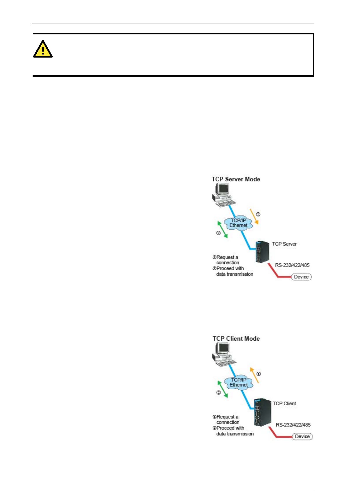
TCP Server Mode
5x50AI-M12 is configured with a
TCP/IP network. NPort
-M12 waits passively to be contacted by the host
allowing the host computer to establish a
—at the same time.
5x50AI-M12.
device. This
8 simultaneous
can collect data from the
1. The host reque s ts a connec tion f ro m the NPort
5x50AI-M12 configured for TCP Server M ode.
2. Once the connec tio n is es tablished, data can be
transmitted in both directions—f ro m the host to the
NPort 5x50AI-M12, and from the NPort 5x50AI-M12 to
the host.
TCP Client Mode
the NPort 5x50AI-M12can active ly
1. The NPort 5x50AI-M12 configured for TCP Client Mode
requests a connection from the host.
2. Once the connec tio n is es tablished, data can be
transmitted in both directions—f ro m the host to the
NPort 5x50AI-M12, and from the NPort 5x50AI-M12 to
the host.
or Inactivity time settings. Refer to
transmission proceeds as
-defined host computer
the NPort can
by using the
Page 21

NPort 5x50AI-M12 Series Choosing the Proper Operation Mo de
4-4
Compared to TCP communication, UDP is faster and more
efficient. In UDP mode, you can not only unicast but also
multicast data from the serial device to multipl e host
computers, and the serial device can also recei
from multiple host computers, making this mode ideal for
message display applications.
UDP Mode
ve data
Pair Connection Mode
Pair Connection Mode employs two NPort 5x50AI-M12 units in tandem, and can be used to remove the
15-meter distance limitation imposed by the RS-232 interface. One NPort 5x50AI-M12 is connected from its
RS-232 port to the COM port of a PC or other type of computer, such as a hand-held PDA, and the serial device
is connected to the RS-232 port of the other NPort 5x50AI-M12. The two NPort 5x50AI-M12 units are then
connected to each other with a cross-over Etherne t c able, both ar e connec te d to the same LAN, or in a more
advanced setup, they communicate with each other ov er a WAN (i.e., thr o ugh o ne or more ro uter s ). Pair
Connection Mode transparently transfers both data and modem control signals (although it cannot transmit the
DCD signal) between the two NPort device servers.
Ethernet Modem Mode
Ethernet Modem Mode is designed for use with legacy operating systems, such as MS-DOS, that do not support
TCP/IP Ethernet. By connecting one of NPort 5x50AI-M12’s serial port to the MS-DOS computer’s serial port, it
is possible to use legacy software originally des igned to transmit data via modem, but now transmit the data
over the Ethernet.
Page 22
NPort 5x50AI-M12 Series Choosing the Proper Operation Mo de
4-5
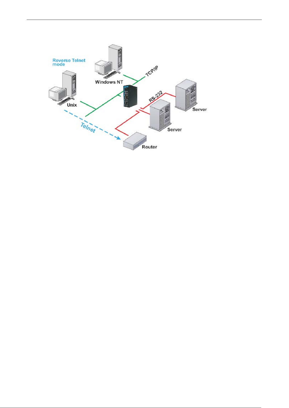
Reverse Telnet Mo d e
Console management is commonly used by connecting to Console/AUX or COM ports of routers, switch es, and
UPS units. Rtelnet works the same as RAW mode in that only one TCP port is listened to after booting up. The
system then waits for a host on the network to initiate a con nection. The difference is that the RAW mode does
not provide the conversion function provide d by T elnet. If the connected devices need to use the CR/LF
conversion function when controlling, then users must choose Rtelnet mode.
Disabled Mode
When the Operation Mode for a particular port is set to Disabled, that port will be disabled.
Page 23

5
5. Web Console Configuration
The Web Console is the m ost user-friendly of the methods available to configure the NPort 5x50AI-M12. In this
chapter, we introduce the Web Console function gr oups and function definitions.
The following topics are covered in this chapter:
Opening Your Browser
Quick Setup
Export/Import
Basic Settings
Network Settings
Serial Settings
Operating Settings
Real COM Mode
RFC2217 Mode
TCP Server Mode
TC P C li e nt Mode
UDP Mode
Pair Connection Mode
Ethe r ne t Modem Mode
Reverse Telnet Mode
D is a b le d Mode
Accessible IP Settings
Auto Warning Setti ng s
A uto warning: Email and SNMP trap
Ev e nt Typ e
Upgrade Firmware
Monitor
Mo nitor Line
Monitor Async
Monitor Async-Settings
Monitor Relay Output
Change Password
Load Factory Default
Save/Restart
Page 24
NPort 5x50AI-M12 Series Web Console Confi guration
5-2
ATTENTION
If you use other web browsers,
allow cookies that are stored on your
computer
NPort
ATTENTION
Refer to Chapter 3,
, to see how to configure the IP address. Examples
shown in this chapter use the Factory Default IP addre ss (19 2 .168 .127.254).
Opening Your Browser
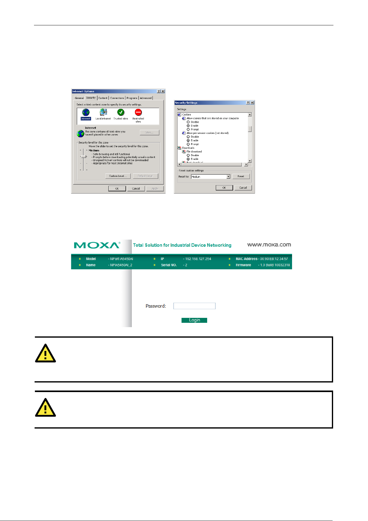
1. Make sure your browser has cookie s enabl e d . To enable cookie s in I nterne t Exp lor er , right click on the
Internet Explorer icon on your desktop, select Properties, click on the Security tab, and then select Enable
under Allow cookies that are stored on your computer, Allo w per -se ssio n cookies (not stored), and File
download.
2. Enter the IP address of your device in the address field of the browser, then press the Enter key. The default
IP address is 192.168.127.254.
3. Input the password if prompted. The password will be transmitted with MD5 encryption over Ethernet. Note
that you will not be prompted to enter the password if the NPort 5x50AI-M12 is not currently
password-protected.
” or “allow per-session cookies.”
5x50AI-M12 uses cookies only for password transmission.
Initial IP Address Configuration
remember to enable the functions to “
Page 25

NPort 5x50AI-M12 Series Web Console Confi guration
5-3
ATTENTION
If you can’t remember the password, the ONLY way to configure
defaults
Remember to
Reset to
default
M12
with the
ATTENTION
If your NPort
function in your browser. If the cookie function is disabled, you will not be allowed to enter the Web Console
Screen.
4. The NPort 5x50AI-M12 homepage will open next. There are two buttons on this page: Quick setup and
Export/Import. You can click Overview at any time to go back to this page. The following sections
introduce these two convenient functions and all the other specific settings in the Main Menu on the left.
by using the “Reset to default” button located at the top side of NPort 5x50AI-M12.
export the configuration file when you have finished the configuration. After using the “
” button to load factory defaults, your configuration can be easily reloaded into the NPort 5x50AI-
Import function.
5x50AI-M12 application r e quires using password protection, you must enable the cookie
Quick Setup
Quick Setup streamlines configuration of your NPort into three basic and quic k steps that cove rs the most
commonly-used settings. At any time while in Quick Setup you may click the Back button to return to the
previous step, or the Cancel button to revers e all se ttings. For more detailed settings, please refer to the
“Basic Settings,” “Network Settings,” “Serial Settings,” and “Operating Settings,” sections later in this chapter.
the NPort 5x50AI-M12 is to load factory
Page 26

NPort 5x50AI-M12 Series Web Console Confi guration
5-4
In Step 1/3, you must assign a valid IP address to the NPort 5x50AI-M12 before it will work in your network
environment. Your network system administrator should provide you with an IP address and related setting s
for your network. In addition, the server name field is a useful way to specify the location or application of
different NPort 5x50AI-M12s.
In the Step 2/3, you must specify which operation mode you will use. If your operation mode is not Real COM,
TCP Server, TCP Client or UDP mode, please click Cancel and to go back to main menu and choose
Operating Settings to select your proper setting.
Page 27

NPort 5x50AI-M12 Series Web Console Confi guration
5-5
In the Step 3/3, you can modify the serial settings.
Review your settings at the Finish Settings page to confirm that they are correct, and then click the
Save/Restart button to restart the de v ice with the ne w settings.
Note that if you changed the IP address, you will not be able to return to the Home Page with the Home button.
Page 28
NPort 5x50AI-M12 Series Web Console Confi guration
5-6
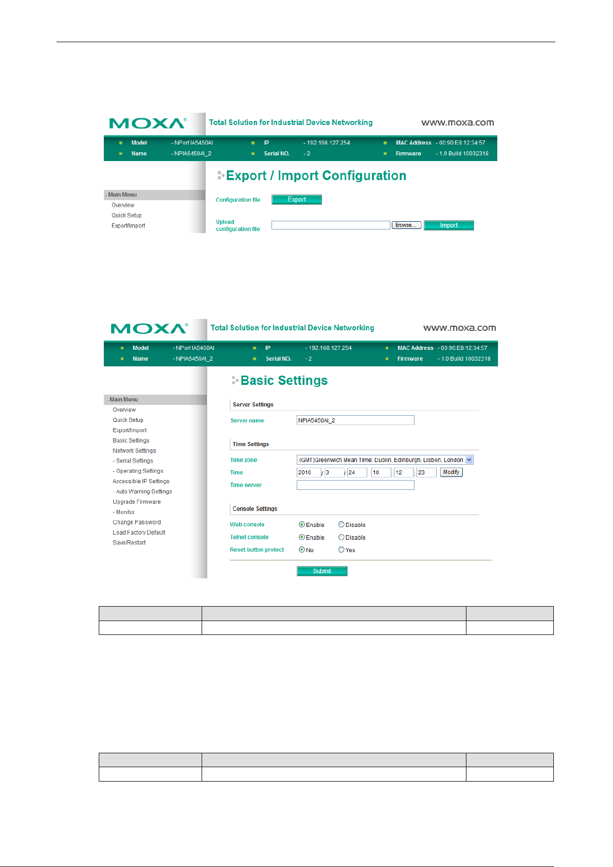
Export/Import
Export/Import allows you to back up and recover your settings.
Click Export to store all configuration data into a default file, <Servername>.txt. Click the Import button to
upload a configuration file to the NPort 5x50AI-M12.
Basic Settings
Server name
Setting Factory Defa ult Necessity
1 to 39 characters NP[model name]_[Serial No.] Optional
This option is useful for specifying the location or application of different NPort 5x50AI-M12s.
Web/Telnet Console
The “Disable” option for “Web Console” and “Telne t Console” is included for security reasons. In some cases,
you may want to disable one or both of these console utilities as an extra precaution to prevent unauthorized
users from accessing your NPort 5x50AI-M12. The factory default for both Web console and Telnet console is
Enable.
Web console
Setting Factory Defa ult Necessity
Enable or Disable Enable Required
Page 29

NPort 5x50AI-M12 Series Web Console Confi guration
5-7
ATTENTION
If you disable both the “Web
you can still use NPort Administrator to configure
NPort
device servers locally or remotely over the network. Refer to Chapter 6 for more details.
(if the
Telnet console
Setting Factory Defa ult Necessity
Enable or Disable Enable Required
5x50AI-M12
Reset button protect
Setting Factory Defa ult Necessity
No or Yes None Optional
console” and “Telnet console,”
Network Settings
You must assign a valid IP address to the NPort 5x50AI-M12 before it will work in your network environment.
Your network system administrator should provide you with an IP address and related settings for your network.
The IP address must be unique within the network (otherwise, the NPort 5x50AI-M12 will not have a valid
connection to the network). First time users can re fe r to Chapter 3, Initial IP Address Configuration, for
more information.
You can choose from four possible IP Configuration modes—Static, DHCP, DHCP/BOOTP, and BOOTP—
located under the web console screen’s IP configuration drop-down box.
IP configuration
Method Function Definition Default
Static User defined IP address, Netmask, Gateway.
DHCP DHCP Server assigned IP address, Netmask, Gateway, DNS,
DHCP/BOOTP DHCP S erver assi gned IP address, Netmask, Gateway, DNS,
BOOTP BOOTP Server assigns IP address
and Time Server
and Time Server, or BOOTP Server assigned IP address
DHCP Server doe s not respond)
Page 30

NPort 5x50AI-M12 Series Web Console Confi guration
5-8
ATTENTION
assigned by the DHCP or BOOTP server. The Timeout for each try increases from 1 second, to 3 seconds, to
(192.168.127.254), Netmask, and Gateway for IP settings.
IP address
Setting Factory Defa ult Necessity
E.g., 192.168.1.1 (IP
addresses of the form
x.x.x.0 and x.x.x.255
are invalid.)
An IP address is a number assigned to a network device (su ch a s a computer) as a permanent a ddress on t he
network. Computers use the IP address to identify and talk to each other over the network. Choose a proper IP
address which is unique and valid in your network environment.
Netmask
Setting Factory Defa ult Necessity
E.g., 255.255.255.0 255.255.255.0 Required
A subnet mask represents all of the network hosts at one geographic location, in one building, or on the same
local area network. When a packet is sent out over the network, the NPort 5x50AI-M12 will use the subnet
mask to check whether the desired TCP/IP host specified in the packet is on the local network segment. If the
address is on the same network segment as the NPort 5x50AI-M12, a connection is established directly from
the NPort 5x50AI-M12. Otherwise, the connectio n is establ is he d thro ugh the given default gateway.
Gateway
Setting Factory Defa ult Necessity
E.g., 192.168.1.1 None Optional
192.168.127.254 Required
A gateway is a network gateway that acts as an entrance to another network . Us ua lly, the computers that
control traffic within the network or at the local I nte r net servic e pro v ide r are gateway nodes. NPort
5x50AI-M12 needs to know the IP address of the default gateway computer in order to communicate with the
hosts outside the local network environment. For correct gateway IP address information, consult the network
administrator.
IP configuration
Setting Factory Defa ult Necessity
Static, DHCP,
DHCP/BOOTP, BOOTP
In Dynamic IP environments, the firmware will retry 3 times every 30 seconds until networ k s e tting s are
5 seconds. If the DHCP/B OOTP Server is unavailable, the firmware will use the default IP address
DNS server 1 / DNS server 2
Setting Factory Defa ult Necessity
(IP addresses of the
form x.x.x.0 an d
x.x.x.255 are invalid.)
Static Required
None Optional
When the user wants to visit a particular website, the computer asks a Domain Name System (DNS) server for
the website’s correct IP address, and then the computer uses the response to connect to the web server. DNS
is the way that Internet domain names are identifie d and translated into IP addresses. A domain name is an
alphanumeric name, such as moxa.com, that it is usually easie r to remember. A DNS server is a host that
translates this kind of text-based domain name into the numer ic I P addres s used to es tablis h a TC P/I P
connection.
In order to use NPort 5x50AI-M12’s DNS feature, you need to configure the DNS server. Doing so allows NPort
5x50AI-M12 to use a host’s domain name to access the host. NPort 5x50AI-M12 provides DNS server 1 and
Page 31

NPort 5x50AI-M12 Series Web Console Confi guration
5-9
DNS server 2 configuration items to configure the IP address of the DNS server. DNS Server 2 is included for
use when DNS sever 1 is unavailable.
NPort 5x50AI-M12 plays the role of DNS client, in the sense that the NPort 5x50AI-M12 will actively query the
DNS server for the IP address associated with a particular doma in name . NPort 5x50AI-M12 f unc tio ns that
support domain name are Time server, Destination IP Address in TCP Client mode, Mail Server, SNMP
trap server, and Auto report to IP.
SNMP Settings
Community name
Setting Factory Defa ult Necessity
1 to 39 characters public Optional
A community name is a plain-text password mechanism that is used to weakly authenticate queries to agents
of managed network devices.
Contact
Setting Factory Defa ult Necessity
1 to 39 characters
(E.g., Support,
886-89191230 #300)
None Optional
The SNMP contact information usually inc ludes an emergency contact name and telephone or pager number.
Location
Setting Factory Defa ult Necessity
1 to 39 characters
(E.g., Floor 1, office 2)
Specify the location string for SNMP agents such as the NPort 5x50AI-M12. This string is usually set to the
street address where the NPort 5x50AI-M12 is physically located.
None Optional
IP Address Report
When NPort 5x50AI-M12 products are used in a dynamic IP environment, users must spend more time with IP
management tasks. For example, if the NPort 5x50AI-M12 works as a server (TCP or UDP), then the host,
which acts as a client, must know the IP address of the server. If the DHCP server assigns a new IP address to
the NPort 5x50AI-M12, the host must have some way of determining the NPort 5x50AI-M12’s new IP address.
NPort 5x50AI-M12 products help out by periodically reporting their IP address to the IP location server, in case
the dynamic IP has changed. The parameters shown below are used to configure the Auto IP report function.
There are two ways to develop an “Auto IP report Server” to receive the NPort 5x50AI-M12’s Auto IP report.
1. Use the NPort Administrator’s IP Address Report function.
2. The Auto IP report protoco l can automaticall y re c e ive the Auto IP repo rt on a regular basis, and is also
available to help you develop your own software. Refer to Appendix E for the “Auto IP report protocol”.
Auto report to IP
Setting Factory Default Necessity
E.g., 192.168.1.1 or
URL
(IP addresses of the
form x.x.x.0 and
x.x.x.255 are invalid.)
Reports generated by the Auto report functio n will b e automatica lly sent to this IP address.
None Optional
Page 32

NPort 5x50AI-M12 Series Web Console Confi guration
5-10
Auto report to TCP port
Setting Factory Defa ult Necessity
E.g., 4001 4002 Optional
Auto report period
Setting Factory Defa ult Necessity
Time interval (in
seconds)
10 Optional
Serial Settings
Click Serial Settings, loc ate d und e r Main Menu, to display serial port settings for port 1.
To modify serial settings for a particular port, click either Port X (X=1 or 2 or 3 or 4) under Seri al Settings,
located under Main Menu on the left side of the browser window.
Page 33

NPort 5x50AI-M12 Series Web Console Confi guration
5-11
ATTENTION
Check the serial communication parameters in your
the NPort
5x50AI
Space, Mark
Port alias
Setting Factory Defa ult Necessity
1 to 15 characters
(E.g., PLC-No.1)
“Port alias” is included to allow easy identification of the serial devices that are connected to the NPort
5x50AI-M12’s serial ports.
None Optional
Serial Parameters
-M12’s serial parameters with the same communication p ara me ter s used by your serial dev ic es.
Baudrate
Setting Factory Defa ult Necessity
50 bps to 921.6 Kbps 115.2 Kbps Required
Data bits
Setting Factory Defa ult Necessity
5, 6, 7, 8 8 Required
When the user sets Data bits to 5 bits, the Stop bits setting will automatically change to 1.5 bits.
Stop bits
Setting Factory Defa ult Necessity
1, 1.5, 2 1 Required
Stop bits will be set to 1.5 when Data bits is set to 5 bits.
Parity
Setting Factory Defa ult Necessity
None, Even, Odd,
Flow control
Setting Factory Defa ult Necessity
None, RTS/CTS,
DTR/DSR, Xon/Xoff
None Required
RTS/CTS Required
serial device’s user’s manual. You should set up
FIFO
Setting Factory Defa ult Necessity
Enable, Disable Enable Required
The NPort 5x50AI-M12’s serial ports provide a 16-byte FIFO in both the Tx and Rx directions. To prevent
unexpected communication, disable the FIFO se tting when your serial device does not have a FIFO.
Interface
Setting Factory Defa ult Necessity
RS-232/422/485 RS-232 Required
Page 34

NPort 5x50AI-M12 Series Web Console Confi guration
5-12
Operating Settings
Click Operating Settings, located under Main Menu, to display the operating settings for both of the NPort
5x50AI-M12’s serial ports.
Real COM Mode
TCP alive check time
Setting Factory Defa ult Necessity
0 to 99 min 7 min Optional
0 min: The TCP connection will not be closed due to an idle TCP connection.
1 to 99 min: NPort 5x50AI-M12 automatically closes the TCP connection if there is no TCP activity for the given
time. After the connection is closed, the NPort 5x50AI-M12 starts listening for another Real COM driver
connection from another host.
Page 35

NPort 5x50AI-M12 Series Web Console Confi guration
5-13
ATTENTION
When “
connection application” (i.e.,
multi connection application,
the
console.
one of the hosts opens
the COM
communication may not work properly.
Max connection
Setting Factory Defa ult Necessity
1, 2, 3, 4, 5, 6, 7, 8 1 Required
Max connection is usually used when the user needs to receive data from different hosts simultaneously. The
factory default is 1. In this case, only one specific host can access this port of the NPort 5x50AI-M12, and the
Real COM driver on that host will have full control over the port.
Max Connection 1:
Allows only 1 host’s Real COM driver to open the specific NPort 5x50AI-M12 serial port.
Max Connection 2 to 8:
Allows 2 to 8 host’s Real COM drivers to open the specific NPort 5x50AI-M12 ser ial p ort, at the same time.
When multiple hosts’ Real COM driv ers open the serial port at the same time, the COM driver only provides a
pure data tunnel without control ability. That is, this serial port parameter will use the firmware’s settings, not
depend on your application program (AP).
Application software that is based on the COM driver will receive a dr i ver respon se of “success” when the
software uses any of the Win32 API functions. The firmware will only send the data back to the driver on the
host.
Data will be sent first-in-first-out when data comes into the NPort 5x50AI-M12 from the Ethernet interface.
Max connection” is set greater than 1, this means that the NPort 5x50AI-M12 will be using a “multi
Up to 8 hosts are allow ed access to the por t at the same time). Whe n us ing a
the NPort 5x50AI-M12 will use the serial communication parameters set in
All of the hosts connected to that port must use the same serial settings. If
port with parameters that are different from the NPort 5x50AI-M12’s console setting, data
Ignore jammed IP
Setting Factory Defa ult Necessity
No or Yes No Optional
By default, when Max connection is greater than 1, and the serial device is transmitting data, if any one of the
connected hosts is not responding, it will w ait until the data has been transmitted successfully before
transmitting the second group of data to all hosts. If you select Yes under Ignore jammed IP, the host that
is not responding will be ignored, but the data will still b e transmitte d to the other hosts.
Allow driver control
Setting Factory Defa ult Necessity
No or Yes No Optional
If Max connection is greater than 1, NPort will ignore driver control commands from all connected hosts.
However, if you set Allow driver control to Yes, control comm ands will be accepted. Note that since the
NPort 5x50AI-M12 may get configuration changes from multiple hosts, the most recent command received will
take precedence.
Packing length
Setting Factory Defa ult Necessity
0 to 1024 0 Optional
Default = 0, The Delimiter Process will be followed, regardless of the length of the data packet. If the data
length (in bytes) matches the configured value, the data will be forced out. The data length can be configured
for 0 to 1024 bytes. Set to 0 if you do not need to limit the length.
Page 36

NPort 5x50AI-M12 Series Web Console Confi guration
5-14
ATTENTION
Delimiter 2
If the size of the serial
data received is greater than 1 KB, the NPort
will automatically pack the data and send it to the
Ethernet port.
miter function, you must at least enable Delimiter 1. If Delimiter 1 is
left blank and Delimiter 2 is enabled, the delimiter function will not work properly.
Setting
Factory Defa ult
Necessity
Delimiter 1
Setting Factory Defa ult Necessity
00 to FF (hex) None Optional
Delimiter 2
Setting Factory Default Necessity
00 to FF (hex) None Optional
Once the NPort 5x50AI-M12 receives both delimiters through its serial port, it immediately packs all data
currently in its buffer and sends it to the NPort 5x50AI-M12’s Ethe rnet port.
Delimiter process
Setting Factory Defa ult Necessity
Do nothing, Delimiter +
1, Delimiter + 2, Strip
Delimiter
Delimiter + 1 or Delimite r + 2: The data will be transmitted when an additional byte (for Delimiter +1), or
an additional 2 bytes (for Delimiter +2) of data is received after receiving the Delimiter.
Strip Delimiter: When the Delimiter is received, the Delimiter is deleted (i.e., stripped), and the re maini ng
data is transmitted.
Do nothing: The data will be transmitted when the Delimiter is received.
Force tran smit
0 to 65535 ms 0 ms Optional
0: Disable the force transmit timeout.
is optional. If left blank, then Delimiter 1 alone trips clearing of the buffer.
5x50AI-M12
However, to use the deli
Do Nothing Optional
1 to 65535: Forces the NPort 5x50AI-M12’s TCP/IP protocol software to try to pack serial data received during
the specified time into the same data frame.
This parameter defines the time interval during which the NPort 5x50AI-M12 fetches the serial data from its
internal buffer. If data is incoming through the serial port, the NPort 5x50AI-M12 stores the data in the internal
buffer. The NPor t 5x50AI-M12 transmits data stor ed in the buffer v ia TCP/IP, but only if the internal buffer is
full or if the Force transmit time interval reac he s the time spec ifie d unde r Force transmit.
The optimal Force transmit timeout depend s on your app licatio n, but it must be at least larger than one
character interval within the specified baudrate. For example, assume that the serial port is set to 1200 bps, 8
data bits, 1 stop bit, and no parity. In this case, the total number of bits needed to send a character is 10 bits,
and the time required to transfer one characte r is
(10 (b its ) / 1200 (bits /s )) * 1000 (ms/s) = 8.3 ms.
Therefore, you should set Force transmit timeout to be larger than 8.3 ms, so in this case, it must be greater
than or equal to 10 ms.
If the user wants to send a series of characters in the same packet, the serial devic e attached to the N Por t
5x50AI-M12 should send that series of characters during a time interval less than the Force transmit timeout
for the NPort 5x50AI-M12, and the total length of data must be less than or equal to the NPort 5x50AI-M12’s
internal buffer size. The serial communic ation buffer size for the NPort 5x50AI-M12 is 1 KB per port.
Page 37

NPort 5x50AI-M12 Series Web Console Confi guration
5-15
RFC2217 Mode
TCP alive check time
Setting Factory Defa ult Necessity
0 to 99 min 7 min Optional
0 min: TCP connection is not closed due to an idle TCP connection.
1 to 99 min: The NPort 5x50AI-M12 automatically closes the TCP connection if there is no TCP activity for the
given time. After the connection is closed, the NPort 5x50AI-M12 starts listening for ano the r host’s TCP
connection.
Local TCP port
Setting Factory Defa ult Necessity
1 to 65535 4001 Required
The Local TCP port is the TCP port that the NPort 5x50AI-M12 use s to listen to co nne c tions, and that o the r
devices must use to contact the NPort 5x50AI-M12. To avoid conflicts with well known TCP ports, the default is
set to 4001.
Packing length
Setting Factory Defa ult Necessity
0 to 1024 0 Optional
Default = 0: The Delimiter Process will be followed, regardless of the length of the data packet. If the data
length (in bytes) matches the configured value, the data will be forced out. The data length can be configured
for 0 to 1024 bytes. Set to 0 if you do not need to limit the length.
Delimiter 1
Setting Factory Defa ult Necessity
00 to FF None Optional
Delimiter 2
Setting Factory Defa ult Necessity
00 to FF None Optional
Page 38

NPort 5x50AI-M12 Series Web Console Confi guration
5-16
Once the NPort 5x50AI-M12 receives both delimiters through its serial port, it immediate ly packs all data
currently in its buffer and sends it out the NPort 5x50AI-M12’s Ethernet port.
Delimiter process
Setting Factory Defa ult Necessity
Do Nothing,
Delimiter + 1,
Delimiter + 2,
Strip Delimiter
Delimiter + 1 or Delimiter + 2: The data will be transmitted when an additional byte (for Delimiter +1), or
an additional 2 bytes (for Delimiter +2) of data is receiv ed afte r r ece iving the Delimiter.
Strip Delimiter: When the Delimiter is received, the Delimiter is deleted (i.e., stripped), and the remaini ng
data is transmitted.
Do Nothing: The data will be transmitted when the Delimiter is received.
Force tran smit
Setting Factory Defa ult Necessity
0 to 65535 ms 0 ms Optional
0: Disable the force transmit timeout.
1 to 65535: Forces the NPort 5x50AI-M12’s TCP /IP prot ocol soft ware t o tr y to pac k seri al d ata received during
the specified time into the same data frame.
This parameter defines the time interval during which the NPort 5x50AI-M12 fetches the serial data from its
internal buffer. If data is incoming through the serial port, the NPort 5x50AI-M12 stores the data in the internal
buffer. The NPor t 5x50AI-M12 transmits data stor ed in the buffer v ia TCP/IP, but only if the internal buffer is
full or if the Force transmit time interval reache s the time spec ifie d unde r For c e trans m it timeo ut.
Do Nothing Optional
The optimal Force transmit timeout depend s on your app licatio n, but it must be at least larger than one
character interval within the specified baudrate. For example, assume that the serial port is set to 1200 bps, 8
data bits, 1 stop bit, and no parity. In this case, the total number of bits needed to send a character is 10 bits,
and the time required to transfer one character is
(10 (bits) / 1200 (bits/s)) * 1000 (ms/s) = 8.3 ms.
Therefore, you should set Force transmit timeout to a value larger than 8.3 ms, so in this case, it must be
greater than or equal to 10 ms.
If the user wants to send a series of characters in the same packet, the serial devic e attached to the NPort
5x50AI-M12 should send that series of characters during a time interval less than the Force transmit timeout
for the NPort 5x50AI-M12, and the total length of data must be less than or equal to the NPort 5x50AI-M12’s
internal buffer size. The serial communic ation buffer size for the NPort 5x50AI-M12 is 1 KB per port.
Page 39

NPort 5x50AI-M12 Series Web Console Confi guration
5-17
TCP Server Mode
TCP alive check time
Setting Factory Defa ult Necessity
0 to 99 min 7 min Optional
0 min: The TCP connection will not be closed due to an idle TCP connection.
1 to 99 min: The NPort 5x50AI-M12 automatically closes the TCP connection if there is no TCP activity for the
given time. After the connection is closed, the NPort 5x50AI-M12 starts listening for another host’s T CP
connection.
Inactivity time
Setting Factory Defa ult Necessity
0 to 65535 ms 0 ms Optional
0 ms: TCP connection wi ll no t be closed due to an idle serial line.
0-65535 ms: The NPort 5x50AI-M12 automatically closes the TCP connection if there is no serial data activity
for the given time. After the connection is closed, the NPort 5x50AI-M12 starts listening for another host’s TCP
connection.
This parameter defines the maintenance status as Clo s ed or Liste n for the TC P connection. The c o nnection is
closed if there is no incoming or outgoing data through the seri al port during the specific Inactivity time.
If the Inactivity time is set to 0, the current TCP connection is kept ac tive until a co nne c tion close request is
received. Although Inactivity time is disabled, the NPort 5x50AI-M12 will check the connection status between
the NPort 5x50AI-M12 and remote host by sending “keep alive” packets periodically. If the remote host does
not respond to the packet, the NPort 5x50AI-M12 assumes that the connection was closed down
unintentionally. The NPort 5x50AI-M12 will then force the existing TCP connection to close.
Page 40

NPort 5x50AI-M12 Series Web Console Confi guration
5-18
ATTENTION
T
. To prevent
the unintended loss of data due to the session disconnect
this value
large enough so that the intended data transfer is completed.
1, 2, 3, 4, 5, 6, 7, 8
1
Required
he Inacti vity time should be configured to be larger than the Force transmit timeout setting
Max connection
Setting Factory Defa ult Necessity
Max connection is usually used when the user needs to receive data from different hosts simultaneously. The
factory default only allows for 1 conne c tion at a time.
Max connection 1: The NPort only allows 1 host to open the TCP connection to the specific serial po rt.
Max connection 2 to 8: Allows 2 to 8 host’s TCP connection request to open this NPort 5x50AI-M12 serial port,
at the same time. When multiple hosts establish a TCP connection to the specific serial port at the same time,
the NPort 5x50AI-M12 will duplicate the serial data and transmit to all of the hosts. Ethernet data is sent on a
first-in-first-out basis to the serial port when data comes into the NPort 5x50AI-M12 fro m the Ethernet
interface.
Ignore jammed IP
Setting Factory Defa ult Necessity
ion, it is highly recommended that you set
No or Yes No Optional
By default, when Max connection is greater than 1, and the serial device is transmitting data, if any one of the
connected hosts is not responding, it will w ait until the data has been transmitted successfully before
transmitting the second group of data to all hosts.If you select Yes for Ignore jammed IP, the host that is not
responding will be ignored, but the data will still be trans m itte d to the othe r ho s ts .
Allow driver control
Setting Factory Defa ult Necessity
No or Yes No Optional
If Max con nectio n is greater than 1, the NPort will ignore driver control commands from all connected hosts.
However, if you set Allow driver control to Yes, control comm ands will be accepted. Note that since the
NPort 5x50AI-M12 may get configuration changes from multiple hosts, the most recent command received will
take precedence.
Packing length
Setting Factory Defa ult Necessity
0 to 1024 0 Optional
Default = 0, The Delimiter Process will be followed, regardless of the length of the data packet. If the data
length (in bytes) matches the configured value, the data will be forced out. The data length can be configured
for 0 to 1024 bytes. Set to 0 if you do not need to limit the length.
Delimiter 1
Setting Factory Defa ult Necessity
00 to FF None Optional
Delimiter 2
Setting Factory Defa ult Necessity
00 to FF None Optional
Once the NPort 5x50AI-M12 receives both delimiters through its serial port, it immediate ly packs all data
currently in its buffer and sends it out the NPort 5x50AI-M12’s Ethernet port.
Page 41

NPort 5x50AI-M12 Series Web Console Confi guration
5-19
ATTENTION
Delimiter 2 is
If the size of the serial
data received is greater than 1 KB, the NPort
will automatically pack the data and send it to the
Ethernet. However, to use the delimiter function, you must at least enab le Delimite r 1. If Delimiter 1 is left
blank and Delimiter 2 is enabled, the delimiter f unc tio n will no t wo rk prope r ly.
1 to 65535
4001
Required
Setting
Factory Defa ult
Necessity
Delimiter process
Setting Factory Defa ult Necessity
Do Nothing,
Delimiter + 1,
Delimiter + 2,
Strip Delimiter
Delimiter + 1 or Delimiter + 2: The data will be transmitted when an additional byte (for Delimiter +1), or
an additional 2 bytes (for Delimiter +2) of data is receiv ed afte r r ece iving the Delimiter.
Strip Delimiter: When the Delimiter is received, the Delimiter is deleted (i.e., stripped), and the remaini ng
data is transmitted.
Do Nothing: The data will be transmitted when the Delimiter is received.
Force tran smit
Setting Factory Defa ult Necessity
0 to 65535 ms 0 ms Optional
optional. If left blank, then Delimiter 1 alone trips clearing of the buffer.
5x50AI-M12
Do Nothing Optional
0: Disable the force transmit timeout.
1 to 65535: Forces the NPort 5x50AI-M12’s TCP/IP protocol software to try to pack serial data received during
the specified time into the same data frame.
This parameter defines the time interval during which the NPort 5x50AI-M12 fetches the serial data from its
internal buffer. If data is incoming through the serial port, the NPort 5x50AI-M12 stores the data in the internal
buffer. The NPort 5x50AI-M12 transmits data stored in the buffer via TCP/I P, but only if the inter nal buffer is
full or if the Force transmit time interval reache s the time spec ifie d unde r For c e trans m it timeo ut.
The optimal Force transmit timeout depend s on your app licatio n, but it must be at least larger than one
character interval within the specified baudrate. For example, assume that the serial port is set to 1200 bps, 8
data bits, 1 stop bit, and no parity. In this case, the total number of bits needed to send a character is 10 bits,
and the time required to transfer one character is
(10 (bits) / 1200 (bits/s)) * 1000 (ms/s) = 8.3 ms.
Therefore, you should set Force transmit timeout to be larger than 8.3 ms, so in this case, it must be greater
than or equal to 10 ms.
If the user wants to send a series of characters in the same packet, the serial device attached to the NPort
5x50AI-M12 should send that series of characters during a time interval less than the Force transmit timeout
for the NPort 5x50AI-M12, and the total length of data must be less than or equal to the NPort 5x50AI-M12’s
internal buffer size. The serial communic ation buffer size for the NPort 5x50AI-M12 is 1 KB per port.
Local TCP port
Setting Factory Defa ult Necessity
The Local TCP port is the TCP port that the NPort 5x50AI-M12 use s to listen to co nne c tions, and that o the r
devices must use to contact the NPort 5x50AI-M12. To avoid conflicts with well known TCP ports, the default is
set to 4001.
Command port
Page 42

NPort 5x50AI-M12 Series Web Console Confi guration
5-20
1 to 65535 966 Optional
The Command port is a listen TCP port for IP-Serial Lib commands from the host. In order to prevent a TCP
port conflict with other applications, the user can set the Command port to another port if needed. IP-Serial Lib
will automatically check the Command Port on NPort 5x50AI-M12 so that the user does not need to configure
the program.
TCP Client Mode
TCP alive check time
Setting Factory Defa ult Necessity
0 to 99 min 7 min Optional
0 min: The TCP connection will not be closed due to an idle TCP connection.
1 to 99 min: The NPort 5x50AI-M12 automatically closes the TCP connection if there is no TCP activity for the
given time.
Inactivity time
Setting Factory Defa ult Necessity
0 to 65535 ms 0 ms Optional
0 ms: The TCP connection will no t be clo sed due to an idle serial line.
Page 43

NPort 5x50AI-M12 Series Web Console Confi guration
5-21
ATTENTION
Inactivity time is ONLY active when
ATTENTION
Delimiter 2 is optional. If left blank, then Delimiter 1 alone trips clearing of the
If the size of the serial
data received is greater than 1 KB, the NPort
will automatically pack the data and send it to the
Ethernet. However, to use the delimiter function, you must at least enab le Delimite r 1. If Delimiter 1 is left
blank and Delimiter 2 is enabled, the delimiter f unc tio n will no t wo rk prope r ly.
0-65535 ms: NPort 5x50AI-M12 automatically closes the TCP connec tion if there is no serial data activity for
the given time.
This parameter defines the maintenance status as Clo s ed or Liste n for the TC P connection. The c o nnection is
closed if there is no incoming or outgoing data through the seri al port during the specific Inactivity time.
If the Inactivity time is set to 0, the current TCP connection is kept active until a conne c tion c lo s e req uest is
received. Although Inactivity time is disabled, the NPort 5x50AI-M12 will check the connection status between
the NPort 5x50AI-M12 and remote host by sending “keep alive” packets periodically. If the remote host does
not respond to the packet, the NPort 5x50AI-M12 assumes that the connection was closed unintentionally.
NPort 5x50AI-M12 will then force the existing TCP connection to close.
Ignore jammed IP
Setting Factory Defa ult Necessity
No or Yes No Optional
By default, when Max connection is greater than 1, and the serial device is transmitting data, if any one of the
connected hosts is not responding, it will w ait until the data has been transmitted successfully before
transmitting the second group of data to all hosts. If you select Yes for Ignore jammed IP, the host that is
not responding will be ignored, but the data will still b e tra nsmitted to the other ho s ts .
Packing length
Setting Factory Defa ult Necessity
0 to 1024 0 Optional
Default = 0, The Delim ite r Proce s s wil l b e follow e d , regard less of the le ng th of the data packe t. If the data
length (in bytes) matches the configured value, the data will be forced out. The data length can be configured
for 0 to 1024 bytes. Set to 0 if you do not need to limit the length.
Delimiter 1
Setting Factory Defa ult Necessity
00 to FF (hex) None Optional
TCP connect on is set to Any character.
Delimiter 2
Setting Factory Defa ult Necessity
00 to FF (hex) None Optional
Once the NPort 5x50AI-M12 receives both delimiters through its serial port, it immediate ly packs all data
currently in its buffer and sends it to the NPort 5x50AI-M12’s Ethernet port.
Delimiter process
Setting Factory Defa ult Necessity
Do Nothing,
Delimiter + 1,
Delimiter + 2,
Strip Delimiter
Do Nothing Optional
5x50AI-M12
buffer.
Page 44

NPort 5x50AI-M12 Series Web Console Confi guration
5-22
ATTENTION
Up to 4 connections can be established between the NPort
and hosts. The connection speed or
throughput may
connection will slow down the
other connections.
ATTENTION
The
. For some applications,
the
Delimiter + 1 or Delimiter + 2: The data will be transmitted when an additional byte (for Delimiter +1), or
an additional 2 bytes (for Delimiter +2) of data is receiv ed afte r r ece iving the Delimiter.
Strip Delimiter: When the Delimiter is received, the Delimiter is deleted (i.e., stripped), and the remaini ng
data is transmitted.
Do Nothing: The data will be transmitted when the Delimiter is received.
Force tran smit
Setting Factory Defa ult Necessity
0 to 65535 ms 0 ms Optional
0: Disable the force transmit timeout.
1 to 65535: Forces the NPort 5x50AI-M12’s TCP/IP protocol software to try to pack serial data received during
the specified time into the same data frame.
This parameter defines the time interval during which the NPort 5x50AI-M12 fetches the serial data from its
internal buffer. If data is incoming through the serial port, the NPort 5x50AI-M12 stores the data in the internal
buffer. The NPort 5x50AI-M12 transmits data stored in the buffer via TCP/I P, but only if the inter nal buffer is
full or if the Force transmit time interval reache s the time spec ifie d unde r For c e trans m it timeo ut.
The optimal Force transmit timeout depend s on your app licatio n, but it must be at least larger than one
character interval within the specified baudrate. For example, assume that the serial port is set to 1200 bps, 8
data bits, 1 stop bit, and no parity. In this case, the total number of bits needed to send a character is 10 bits,
and the time required to transfer one character is
(10 (bits) / 1200 (bits/s)) * 1000 (ms/s) = 8.3 ms.
Therefore, you should set Force transmit timeout to be larger than 8.3 ms, so in this case, it must be greater
than or equal to 10 ms.
If the user wants to send a series of characters in the same packet, the serial device attached to the NPort
5x50AI-M12 should send that series of characters during a time interval less than the Force transmit timeout
for the NPort 5x50AI-M12, and the total length of data must be less than or equal to the NPort 5x50AI-M12’s
internal buffer size. The serial communic ation buffer size for the NPort 5x50AI-M12 is 1 KB per port.
Destination IP addr e ss Function Name
Setting Description Factory Defa ult
Setting Description Default
1/2/3/4
Setting Factory Defa ult Necessity
IP address or Domain
Name
(E.g., 192.168.1.1)
Allows the NPort 5x50AI-M12 to connect actively to the remote host whose IP add ress is set by this parameter.
be low if one of the four connections is slow, since one slow
None Required
5x50AI-M12
Destination IP address parameter can use both IP address and Domain Name
user may need to send the data actively to the remote destination domain name.
Page 45

NPort 5x50AI-M12 Series Web Console Confi guration
5-23
received, and will
received, and will
received, and will
Designated Local Port 1/2/3/4
Setting Factory Defa ult Necessity
TCP Port No. 5011 (Port 1)
5012 (Port 2)
5013 (Port 3)
5014 (Port 4)
Connection control
Setting Factory Defa ult Necessity
Startup/None, Any Character /None ,
Any Character/Inactivity Time,
DSR ON/DSR OFF, DSR ON/None,
DCD ON/DCD OFF, DCD ON/None
The meaning of each of the above settings is given in the table below. In general, both the Connect condition
and Disconnect condition are given.
Connect/Disconnect Description
Startup/None
(default)
Any Character/None A TCP connection will be established when any character is received from the serial
Any Character/
Inactivity Time
DSR On/DSR Off A TCP connection will be established when a DSR “On” signal is
DSR On/None A TCP connection will be established when a DSR “On” signal is received, and will
DCD On/DCD O ff A TCP connection will be established when a DCD “On” signal is
DCD On/None A TCP connection will be established when a DCD “On” signal is
A TCP connection will be established on startup, and will remain active indefinitely.
interface, and will remain active indefinitely.
A TCP connection will be established when any character is received from the serial
interface, and will be disconnected when the Inactivity time out is reached.
be disconnected when a DSR “Off” signal is received.
remain active indefinitely.
be disconnected when a DCD “Off” signal is received.
remain active indefinitely.
Startup/None Required
Required
Page 46

NPort 5x50AI-M12 Series Web Console Confi guration
5-24
ATTENTION
Delimiter 2 is optional. If left blank, then Delimiter 1 alone trips clearing of the
If the size of the serial
data received is greater than 1 KB, the NPort
will automatically pack the data and send it to the
Ethernet. However, to use the delimiter function, you must at least enab le Delimite r 1. If Delimiter 1 is left
b
UDP Mode
Packing length
Setting Factory Defa ult Necessity
0 to 1024 0 Optional
Default = 0, The Delimiter Process will be followed, regardless of the length of the data packet. If the data
length (in bytes) matches the configured value, the data will be forced out. The data length can be configured
for 0 to 1024 bytes. Set to 0 if you do not need to limit the length.
Delimiter 1
Setting Factory Defa ult Necessity
00 to FF None Optional
Delimiter 2
Setting Factory Defa ult Necessity
00 to FF None Optional
Once the NPort 5x50AI-M12 receives both delimiters through its serial port, it immediately packs all data
currently in its buffer and sends it out the NPort 5x50AI-M12’s Ethernet port.
5x50AI-M12
buffer.
lank and Delimiter 2 is enabled, the delimiter function will not work properly.
Delimiter process
Setting Factory Defa ult Necessity
Do Nothing,
Delimiter + 1,
Delimiter + 2,
Strip Delimiter
Do Nothing Optional
Page 47

NPort 5x50AI-M12 Series Web Console Confi guration
5-25
Delimiter + 1 or Delimiter + 2: The data will be transmitted when an additional byte (for Delimiter +1), or
an additional 2 bytes (for Delimiter +2) of data is receiv ed afte r r ece iving the Delimiter.
Strip Delimiter: When the Delimiter is received, the Delimiter is deleted (i.e., stripped), and the remaining
data is transmitted.
Do Nothing: The data will be transmitted when the Delimiter is received.
Force tran smit
Setting Factory Defa ult Necessity
0 to 65535 ms 0 ms Optional
0: Disable the force transmit timeout.
1 to 65535: Forces the NPort 5x50AI-M12’s TCP/IP protocol software to try to pack serial data received during
the specified time into the same data frame.
This parameter defines the time interval during which the NPort 5x50AI-M12 fetches the serial data from its
internal buffer. If data is incoming through the serial port, the NPort 5x50AI-M12 stores the data in the internal
buffer. The NPor t 5x50AI-M12 transmits data stor ed in the buffer v ia TCP/IP, but only if the internal buffer is
full or if the Force transmit time interval reache s the time spec ifie d unde r For c e trans m it timeo ut.
The optimal Force transmit timeout depend s on your app licatio n, but it must be at least larger than one
character interval within the specified baudrate. For example, assume that the serial port is set to 1200 bps, 8
data bits, 1 stop bit, and no parity. In this case, the total number of bits needed to send a character is 10 bits,
and the time required to transfer one character is
(10 (bits) / 1200 (bits/s)) * 1000 (ms/s) = 8.3 ms.
Therefore, you should se t Force tr a nsmit timeout to a value larger than 8.3 ms, so in this case, it must be
greater than or equal to 10 ms.
If the user wants to send a series of characters in the same packet, the serial devic e attached to the NPort
5x50AI-M12 should send that series of characters during a time interval less than the Force transmit timeout
for the NPort 5x50AI-M12, and the total length of data must be less than or equal to the NPort 5x50AI-M12’s
internal buffer size. The serial communic ation buffer size for the NPort 5x50AI-M12 is 1 KB per port.
Destination IP addr e ss 1
Setting Factory Defa ult Necessity
IP address range
E.g., Begin: 192.168.1.1
End: 192.168.1.10
Destination IP addr e ss 2/ 3/4
Setting Factory Default Necessity
IP address range
E.g., Begin: 192.168.1.11
End: 192.168.1.20
Local listen port
Setting Factory Defa ult Necessity
1 to 65535 4001 Required
Begin: Empty Required
End: Empty
Port: 4001
Begin: Empty Optional
End: Empty
Port: 4001
To avoid conflicts with well known U DP ports, the UDP port that the NPort 5x50AI-M12 listens to, and that other
devices must use to contact the NPort 5x50AI-M12, should be set to the default value of 4001.
UDP Multicast
A multicast packet is a packet sent by one host to multiple hosts. In multicast mode, hosts that belong to a
specific multicast group will recei v e multic as t p ack e ts s e nt to that group. When configuring a host as a
multicast receiver over the Internet, routers on the host’ s LAN must be informed. The Internet Group
Page 48

NPort 5x50AI-M12 Series Web Console Confi guration
5-26
Management Protocol (IGMP) is used to communicate gr oup membership information between hosts and
routers on a LAN. The NPort 5x50AI-M12 supports IGMP version 2.
To add a network host to the multicast group, input the host’s IP address (e.g ., 239 .1.1.1) in one of the
Destination IP addr e ss input boxes, as illustrated above. The NPort will automatically add this host to the
multicast group, and the host will start receiving all packets sent by the NPort to this group.
Pair Connection Mode
Pair Connection Mode employs two NPort 5x50AI-M12 device servers in tandem, and can be used to remove
the 15-meter distance limitation impo s ed by the RS-232/422 /48 5 inte rface. One NPort 5x50AI-M12 is
connected from its RS-232/422/485 port to the COM port of a PC or other type of computer, such as hand-held
PDAs that have a serial port, and the serial device is connected to the RS-232/422/485 port of the other NPort
5x50AI-M12. The two NPort 5x50AI-M12 device servers are then connected to each other with a cross-over
Ethernet cable, both are connected to the same LAN, or in a more advanced setup, they communicate with each
other over a WAN (i.e., through one or more routers). Pair Connection Mode transparently transfers both data
and modem control signals (although it cannot trans mit the DCD sig nal) b e twe e n the two NPorts .
Pair Connection Master Mode
When you select Pair Connection Master Mode for the Operation mode of one of the NPort 5x50AI-M12
device servers this NPort 5x50AI-M12 will be acting as a TCP client.
Page 49

NPort 5x50AI-M12 Series Web Console Confi guration
5-27
4001)
TCP alive check time
Setting Factory Defa ult Necessity
0 to 99 min 7 min Required
0 min: TCP connection is not closed due to an idle TCP connection.
1 to 99 min: The NPort 5x50AI-M12 closes the TCP connection automatically if there is no TCP activity for the
given time.
Destination IP addr e ss
Setting Factory Defa ult Necessity
IP address or Domain Name
(E.g., 192.168.1.1)
TCP port No. 4001 Required
The Pair Connection “Master” will contact the ne twork ho s t that has this IP add re s s . Data will be trans mi tte d
through the port No. (4001 by default). Note that you must conf ig ure the sa me TCP por t No. for the device
server acting as the Pair Connection “Slave.”
blank Optional
Pair Connection Slave Mode
When you select Pair Connection Slave Mode for the Operation mode of one of the NPort 5x50AI-M12 device
servers this NPort 5x50AI-M12 will be acting as a TCP server.
TCP alive check time
Setting Factory Defa ult Necessity
0 to 99 min 7 min Required
0 min: TCP connection is not closed due to an idle TCP connection.
1 to 99 min: The NPort 5x50AI-M12 closes the TCP connection automatically if there is no TCP activity for the
given time.
Local TCP port
Setting Factory Defa ult Necessity
TCP port No. (e.g.,
This Port No. must be the same port No. that you set up for the Pair Connection “Master” dev i ce server
4001 Required
Page 50

NPort 5x50AI-M12 Series Web Console Confi guration
5-28
NOTE
The “+++” command cannot be divided. The “+” character can be changed in register S2, and the guard time,
which prefixes and suffixes the “+++” in order to protec t the raw data, can be chang ed in regis te r S12.
Ethernet Modem Mode
Dial-in
The NPort 5x50AI-M12 listens for a TCP/IP connection request from the remote Ethernet modem or host. The
NPort 5x50AI-M12’s response depends on the ATS0 value, as outlined below.
ATS0=0 (default):
The NPort 5x50AI-M12 will temporarily accept the TCP connection and then send the “RING” signal out through
the serial port. The serial controller must reply with “ATA” within 2.5 seconds to accept the connection request,
after which the NPort 5x50AI-M12 enters data mode. If no “ATA” command is received, the NPort 5x50AI-M12
will disconnect after sending three “RING” signals.
≧1:
ATS0
The NPort 5x50AI-M12 will accep t the TC P conne c tion immediately and then send the “CONNECT
<baud>“ command to the serial por t, in which <b aud> repres e nts the baudr a te of the NPort 5x50AI-M12’s
serial port. After that, the NPort 5x50AI-M12 immediately enters data mode.
Dial-out
The NPort 5x50AI-M12 accepts the AT command “ATD <IP>:<TCP port>“ from the serial port and then
requests a TCP connection from the remote Ethernet Modem or PC. This is where <IP> is the IP address of the
remote Ethernet modem or PC, and <TCP port> is the TCP port number of the remote Ethernet modem or PC.
Once the remote unit accepts this TCP connection, the NPort 5x50AI-M12 will send out the “CONNECT
<baud>“ signal via the ser ial por t and then e nte r d ata mode.
Disconnection request from local site
When the NPort 5x50AI-M12s is in data mode, the user can drive the DTR signal to OFF, or send “+++” from
the local serial port to the NPort 5x50AI-M12. The NPort 5x50AI-M12 will enter command mode and return “NO
CARRIER” via the serial port, and then inp ut “ATH” to shut down the TCP connection after 1 second.
After the TCP connection has been shut down by the remote Ethernet modem or PC, the NPort 5x50AI-M12 will
send the “NO CARRIER” signal via the serial port and then return to command mode.
Page 51

NPort 5x50AI-M12 Series Web Console Confi guration
5-29
4=error
(default)
always ready AT&D1, AT&D2=reply DTE when DTR
3
S2
Escape code character (default=43 ASCII “+”)
AT Commands
The NPort 5x50AI-M12 supports the fo llowing common AT commands used with a typical modem:
No. AT command Description Remarks
1 ATA Answer manually
2 ATD <IP>:<Port> Dial up the IP address: Port No.
3 ATE ATE0=Echo OFF
ATE1=Echo ON (default)
4 ATH ATH0=On-hook (default)
ATH1=Off-hook
5 ATI, ATI0, ATI1, ATI2 Modem version reply “OK” only
6 ATL Speaker volume option reply “OK” only
7 ATM Speaker control option reply “OK” only
8 ATO On line comm and
9 ATP, ATT Set Pulse/Tone Dialing mode reply “OK” only
10 ATQ0, ATQ1 Quiet command (default=ATQ0)
11 ATSr=n Change the contents of S register See “S registers”
12 ATSr? Read the contents of S register See “S registers”
13 ATV Result code type
ATV0 for digit code
ATV1 for text code
0=OK
1=connect (default)
2=ring
3=No carrier
14 ATZ Reset (disconnect, e nter command mod e and
restore the flash settings)
15 AT&C Serial port DCD control AT&C0=DCD always on
AT&C1=DTE detects connection by DCD on/off
16 AT&D Serial port DTR control AT&D0=recognize DTE
On (default)
17 AT&F Restore manufacturer’s settings
18 AT&G Select guard time reply “OK” only
19 AT&R Serial port RTS option command reply “OK” only
20 AT&S Serial port DSR control reply “OK” only
21 AT&V View settings
22 AT&W Write current settings to flash for next boot up
S Registers
No. S Register Description & default value Remarks
1 S0 Ring to auto-answer (default= 0)
2 S1 Ring counter (always=0 ) no action applied
4 S3 Return character (default=13 ASCII)
5 S4 Line feed character (def ault=1 0 ASCII)
6 S5 Backspace character (default= 8 ASCII)
7 S6 Wait time for dial tone (always=2, unit=sec) no action applied
8 S7 Wait time for carrier (default=3 , unit= s e c )
Page 52

NPort 5x50AI-M12 Series Web Console Confi guration
5-30
9 S8 Pause time for dial delay (always=2 , unit=sec) no action applie d
10 S9 Carrier detect re s pons e time (always=6, unit 1/10 sec) no action applied
11 S10 Delay for hang up after carrier
(always=14, unit 1/10 sec)
12 S11 DTMF duration and spacing (always=100 ms) no action applied
13 S12 Escape code guard time
(default=50, unit 1/50 sec)
to control the idle time for “+++”
TCP alive check time
Setting Factory Defa ult Necessity
0 to 99 min 7 min Required
0 min: TCP connection is not closed due to an idle TCP connection.
1 to 99 min: The NPort 5x50AI-M12 closes the TCP connection automatically if there is no TCP activity for the
given time.
Local TCP port
Setting Factory Defa ult Necessity
1 to 65535 4001 Required
no action applied
The TCP port that other devices must use to contact this device. To avoid conflicts with standard TCP ports, the
default is set to 4001.
Reverse Telnet M od e
TCP alive check time
Setting Factory Defa ult Necessity
0 to 99 min 7 min Optional
0 min: TCP connection is not closed due to an idle TCP connection.
1 to 99 min: The NPort 5x50AI-M12 automatically closes the TCP connection if there is no TCP activity for the
given time.
Inactivity time
Setting Factory Defa ult Necessity
0 to 65535 ms 0 Optional
Idle time setting for auto-disconnection. 0 min. means it will never disconnect.
Page 53

NPort 5x50AI-M12 Series Web Console Confi guration
5-31
Local TCP port
Setting Factory Defa ult Necessity
1 to 65535 4001 Required
Each of the NPort 5x50AI-M12’s serial ports is mapped to a TCP port. To avoid conflicts with common TCP port
numbers, set port numb e rs to 4001 for port 1, 4002 for port 2, etc.
Map <CR-LF>
Setting Factory Defa ult Necessity
CR, LF, or CR-LF CR-LF Required
If data received through the NPort 5x50AI-M12’s Ethernet port is sent using the “enter” command, the data will
be transmitted out the serial port with an added
“carriage return + line feed” if you select the <CR-LF> option
(i.e., the cursor will jump to the next line, and return to the firs t c harac te r of the line)
“carriage return” if you select the <CR> option
(i.e., the cursor will return to the first character of the line)
“line feed” if you select the <LF> option.
(i.e., the cursor will jump to the next line, but not move horizontally)
Disabled Mode
When Operation mode is set to Disabled, that particular po rt w ill b e d is abled. Check the “Apply the above
settings to all serial ports” to apply this setti ng to the other po r t.
Page 54

NPort 5x50AI-M12 Series Web Console Confi guration
5-32
Accessible IP Settings
The NPort 5x50AI-M12 uses an IP address based filtering method to control ac ces s to itself.
Accessible IP Settings allows you to add or block remote host I P addres s es to preve nt unauthor i ze d acce ss.
Access to the NPort 5x50AI-M12 is controlled by IP address. That is, if a host’s IP address is in th e a ccessibl e
IP table, then the host will be allowed to access the NPort 5x50AI-M12. You can allow one of the following cases
by setting the parameter.
Only one host with a specific IP address can access the NPort 5x50AI-M12
Enter “IP address/255.255.255.255” (e.g., “192.168.1.1/255.255.255.255”).
Hosts on a specific subnet can access the NPort 5x50AI-M12
Enter “IP address/255.255.255.0” (e.g., “192.168.1.0/255.255.255.0”).
Any host can access the NPort 5x50AI-M12
Disable this function by un-checking the “Enable the accessible IP list” checkbox. Refer to the following table for
more configuration examples.
Allowable Hosts Input format
Any host Disable
192.168.1.120 192.168.1.120 / 255. 255.255.25 5
192.168.1.1 to 192.168.1.254 192.168.1.0 / 255.255.25 5.0
192.168.0.1 to 192.168.255.254 192.168.0.0 / 255.255.0. 0
192.168.1.1 to 192.168.1.126 192.168.1.0 / 255.255.25 5.128
192.168.1.129 to 192.168.1.254 192.168.1.128 / 255.255. 255.128
Page 55

NPort 5x50AI-M12 Series Web Console Confi guration
5-33
Auto Warning Settings
Auto warning: Email and SNMP trap
Mail Server
Mail server
Setting Factory Defa ult Necessity
IP Address or Domain
Name
User name
Setting Factory Defa ult Necessity
1 to 15 characters None Optional
Password
Setting Factory Defa ult Necessity
1 to 15 characters None Optional
From E-mail address
Setting Factory Defa ult Necessity
1 to 63 characters None Optional
E-mail address 1/2/3/4
Setting Factory Defa ult Necessity
1 to 63 characters None Optional
None Optional
Page 56

NPort 5x50AI-M12 Series Web Console Confi guration
5-34
ATTENTION
Consult your Network Administrator or ISP for the proper mail server settings. The Auto warning function may
not work properly if it is not configured correctly.
SMTP AUTH supports LOGIN, PLAIN,
CRAM
-MD5 (RFC 2554).
SNMP Trap Server
SNMP trap server IP or domain name
Setting Factory Defa ult Necessity
IP address or Domain
Name
Event Type
the NPort 5x50AI-M12
None Optional
Cold start
This refers to starting the system from power off (contrast this with warm start). When performing a cold start,
the NPort 5x50AI-M12 will automatically issue an Auto warning message by e-mail, or send an SNMP trap after
booting up.
Warm start
This refers to restarting the computer without turning the power off. When performing a warm start, the NPort
5x50AI-M12 will automatically send an e-mail, or send an SNMP trap after rebooting.
Page 57

NPort 5x50AI-M12 Series Web Console Confi guration
5-35
Authentication failure
The user inputs a wrong pass word from the Console or Administrator. When authentication failure occurs, the
NPort will immediately send an e -mail or send an SNMP trap.
IP address changed
The user has changed the NPort 5x50AI-M12’s IP address. When the IP address changes, the NPort
5x50AI-M12 will send an e-mail with the new IP address before the NPort 5x50AI-M12 reboots. If the NPort
5x50AI-M12 is unable to send an e-mail message to the mail server within 15 seconds, the NPort 5x50AI-M12
will reboot anyway, and abort the e-mail auto warning.
Password changed
The user has changed the NPort 5x50AI-M12’s password. When the password changes, the NPort 5x50AI-M12
will send an e-mail with the password changed notice before the NPort 5x50AI-M12 reboots. If the NPort
5x50AI-M12 is unable to send an e-mail message to the mail server within 15 seconds, the NPort 5x50AI-M12
will reboot anyway, and abort the e-mail auto warning.
Power failure
We provide two DC power inputs for redundancy. the NPort 5x50AI-M12 Series supports different approaches
to warn engineers automatically, such as by email or rel ay output. Users can connect to “Monitor -> Relay
Output” from the web console to check what event causes the warning. The relay output will be canceled after
the power recovers, or by selecting “acknowledge eve nt” using the web cons o l e or Telnet. When the Relay
Output is sending a warning, the Ready LED will flash red until the warning event ceases.
Ethernet link down
NPort 5x50AI-M12 Series provides system maintainers with real-time alarm messages for Ethernet link down.
Even when control engineers are out of the control room for an extended per i od of time , they c an still b e
informed of the status of devices almost instantaneously when exceptions occur. the NPort 5x50AI-M12 Series
supports different methods for warning engineers automatically, such as by email, SNMP trap, and relay output.
Users can connect to “Monitor -> Relay” Output from the web console to check which Ethernet port is causing
the warning. The relay output will be canceled if the faile d Etherne t link is restored, or by selecting
Acknowledge Event from the web console or Telnet. When the Relay Output is issuing a warning, the Ready
LED will flash in red until the warning event ceases.
DCD changed
The DCD (Data Carrier Detect) signal has changed, also indicating that the modem connection status has
changed. For example, a DCD change to high also means “Connected” between local modem and remote
modem. If the DCD signal changes to low, it also means that the connection li ne is down.
When the DCD changes, the NPort 5x50AI-M12 will immediately send an e-mail, send an SNMP trap,or trigger
the relay output..
DSR changed
The DSR (Data Set Ready) signal has changed, also indicating that the data communication equipment’s power
is off. For example, a DSR change to high also means that the DCE is powered ON. If the DSR signal changes
to low, it also means that the DCE is powered off.
When the DSR changes, the NPort 5x50AI-M12 will immediately send an e-mail, send an SNMP trap, or trigger
the relay output.
Mail
Setting Factory Defa ult Necessity
Enable, Disable Disable Optional
This feature helps the administrator manage how the NPort 5x50AI-M12 sends e-mail to pre-defined e-mail
boxes when the enabled events—such as Cold start, Warm start, A uthe ntic a tio n failure, etc.—occur. To
configure this feature, click the Event Type Mail c heckb ox .
Page 58

NPort 5x50AI-M12 Series Web Console Confi guration
5-36
Trap
Setting Factory Defa ult Necessity
Enable, Disable Disable Optional
This feature helps the administrator manage how the NPort 5x50AI-M12 sends SNMP Trap to a pre-defined
SNMP Trap server when the enabled events—such as Cold start, Warm start, Authentication failure, etc.—occur.
To configure this feature, click the Event Type Trap checkb ox .
Upgrade Firmware
Keep your NPort 5x50AI-M12 up to date with the latest firmware from Moxa. Occasionally, compare your NPort
firmware to the version currently available at the Moxa website (www.moxa.com
version, you can download it and click Import to upgrade your firmware.
Monitor
Monitor Line
Click Line under Monitor to show the operation mode and status of each TCP/IP connection (IPx) for the serial
ports.
), If there is a new firmware
Page 59

NPort 5x50AI-M12 Series Web Console Confi guration
5-37
Monitor Async
Click Async under Monitor to show the current status of the serial port.
Monitor Async-Settings
Click Async Setting under Monitor to show the run-time settings for the serial port.
Page 60

NPort 5x50AI-M12 Series Web Console Confi guration
5-38
ATTENTION
If you forget the password, the ONLY way to configure
”
button on
Remember to export the configuration file w he n you finish the c onfiguration. By using the Import function
your configuration can be re
Monitor Relay Output
Click Relay Output under Monitor to show the current status of the relay output. To cease the Relay Output
warning, click on the Acknowledge Event button.
Change Password
Input the “Old password” and “New password” to change the password. Le ave the p asswo rd boxe s blank to
erase the password. If the password is erased, then the NPort 5x50AI-M12 will not have password protection.
the NPort 5x50AI-M12’s top side to “Load Factory Default.”
-loaded into the NPort 5x50AI-M12 after using “Load Factory Default.”
the NPort 5x50AI-M12 is by using the “Reset to default
Page 61

NPort 5x50AI-M12 Series Web Console Confi guration
5-39
Load Factory Default
This function will reset all of the NPort 5x50AI-M12’s settings to the factory default values. Be aware that
previous settings will be lost.
Save/Restart
Click Save/Restart will save the current configured settings and restart the NPort 5x50AI-M12 to take effect.
Page 62

6
6. Configuring NPort Administrator
The following topics are covered in this chapter:
Overview
Installing NPort Administrator
Configuration
Bro adcast Search
Unlock Password Protection
Configuring the NPort 5x50AI-M12
Upgrading the Firmware
Export Configuration
Import Configuration
Monitor
Port Monitor
COM Mapping
On-line CO M Mapp ing
Off-line COM Mapping
COM Grouping
IP Address Report
Page 63

NPort 5x50AI-M12 Series Configuring NPort Administrat or
6-2
Overview
NPort Administrator lets you install and configure your NPort 5x50AI-M12 Series products easily over the
network. Five function groups are provid ed to ease the installation process, allow off-line COM mapping, a nd
provide monitoring and IP location serv er functions.
NPort Administrator is an integrated software suite that bundles NPort Administrator and the IP Serial Library,
and provides everything you need to manage, monitor , and mod ify your NPort 5x50AI-M12 from a remote
location.
In this chapter, all the figures are captured by the NPort 5x50AI-M12 Series for demonstration.
Installing NPort Administrator
1. Once the Setup program starts running, click Next when the Welcome window opens to proceed with the
installation.
2. Click Next to install program files in the default direc tory , or se le c t an alter native location.
Page 64

NPort 5x50AI-M12 Series Configuring NPort Administrat or
6-3
3. Click Next to install the program using the default program name, or select a different name.
4. Click Install to proceed with the installation.
5. The Installing window reports the progress of the installation.
Page 65

NPort 5x50AI-M12 Series Configuring NPort Administrat or
6-4
6. Click Next to proceed with the installation.
7. Click Finish to complete the installation of NPort Ad m inis tratio n Suite.
Configuration
The Administrator-Config uratio n w indo w is div ide d into fo ur parts .
• The top section contains the function list and online help area. (Windows NT does not support this .chm file
format.)
• The five Administrator function group s are lis ted in the left section.
• A list of NPort 5x50AI-M12 serial device servers, each of which can be selected to process user
requirements, is displayed in the right secti o n.
• The activity Log, which displays messages that record the user’s processing history, is shown in the bottom
section.
Page 66

NPort 5x50AI-M12 Series Configuring NPort Administrat or
6-5
Broadcast Search
The Broadcast Search function is used to locate all NPort 5x50AI-M12s that are connected to the same LAN
as your computer. Since the B roadcast Search function sear ches by MAC a ddress an d n ot I P address, all NPort
5x50AI-M12s connected to the LAN will be located, regardless of whether or not they are part of the same
subnet as the host.
1. Position the cursor in the right middle section of the Administrator window and then click the right mouse
button.
2. The Broadcast Sear ch window will open and display the Model, IP Address, MAC Address, and Progress of
the search for that particular device.
Page 67

NPort 5x50AI-M12 Series Configuring NPort Administrat or
6-6
ATTENTION
Before modifying
5x50AI
.
3. When the search is complete, the Bro ad c ast Sear c h window will close, and the NPort 5x50AI-M12s that
were located will be displayed in the right pane of the Administrator window. If you found more than one
server connected to this network, refer to the MAC address sticker on your server(s) to determine which
server(s) are the ones you wish to configure. To configure an NPort 5x50AI-M12, place the cursor over the
row displaying that NPort 5x50AI-M12’s information, and then do ub le click the le ft mouse button.
-M12s connected to the LAN, or use Specify by IP Addre ss to locate a particular NPort 5x50AI-M12
the NPort 5x50AI-M12’s configuration, use Broadcast Search to locate all NPort
Unlock Password Protection
If the NPort 5x50AI-M12 is password protected (indicated by “Lock” for Status), you will receive the following
error, and you will not be able to use the right click method to open the configuration page.
In this case, proceed as follows to “Unlock” the device server.
1. Select the NPort 5x50AI-M12 with “Lock” status, click the right mouse button, and the n select Unlock.
2. After inputting the correct password, the Administrator will displa y an “Unlock ok” message.
Page 68

NPort 5x50AI-M12 Series Configuring NPort Administrat or
6-7
3. The “Lock” status will change to “Unlock,” and the Administrator utility will keep this NPort 5x50AI-M12 in
the Unlock status throughout this Administrator session.
The meanings of the six “Status” states are given below (note that the ter m Fixed is borr owe d fr om the
standard fixed IP address networking term inology):
Lock
The NPort 5x50AI-M12 is password protected, “Broadcast Search” was used to locate it, and the password has
not yet been entered from within the current Administrator session.
Unlock
The NPort 5x50AI-M12 is password protected, “Broadcast Search” was used to locate it, and the password has
been entered from within the current Administrator session. Henceforth during this Administrato r se ssion,
activating various utilities fo r this NPort 5x50AI-M12 will not require re-entering the serve r pas swor d.
Blank
The NPort 5x50AI-M12 is not password prote c ted, a nd “Broadc as t Searc h” was used to locate it.
Fixed
The NPort 5x50AI-M12 is not password protected, and “Search by IP address” was used to locate it.
Lock Fixed
The NPort 5x50AI-M12 is password protected, “Specify by IP address” was used to locate it, and the password
has not yet been entered from within the current Adminis trato r s ess io n.
Unlock Fixed
The NPort 5x50AI-M12 is password protected, “Specify by IP address” was us ed to locate it, and the password
has been entered from within the current Administrator session. Henceforth during this Administrator session,
activating various utilities fo r this NPort 5x50AI-M12 will not require re-e ntering the server password.
Configuring the NPort 5x50AI-M12
In this section, we illustrate how to access the NPort 5x50AI-M12’s configuration utility. You should first make
sure that you can connect over the network from your computer to the NPort 5x50AI-M12.
1. To start NPort Administrator, click Start NPort Administration Suite NPort Administrator.
Page 69

NPort 5x50AI-M12 Series Configuring NPort Administrat or
6-8
ATTENTION
You can simultaneously modify the configurations of multiple NPort
s that are of the same model.
To select multiple
s,
or hold down the Shift key to select a group of NPort
2. Unlock the NPort 5x50AI-M12 you wish to configure if it is passwor d prote c te d . Rig ht click the NPort
5x50AI-M12 and select Configure to start the configuration.
3. The progress bar shows that Admini s tr a tor is re trieving configuration information from the specif ic NPor t
5x50AI-M12.
4. Refer to Chapter 5 for each param eter’s function definition. To modify the configuration, you must first click
in the modify box t o ac tivate the parameter setting box.
NPort 5x50AI-M12s, hold down the Ctrl key when selecting additional NPort 5x50AI-M12
5x50AI-M12
5x50AI-M12s.
Page 70

NPort 5x50AI-M12 Series Configuring NPort Administrat or
6-9
Upgrading the Firmware
Follow these steps to upgrade the firmware of an NPort 5x50AI-M12.
1. To start NPort Administrator, click Start NPort Administration Suite NPort Administrator.
2. Unlock the NPort 5x50AI-M12 you wish to configure if it is password protected. Right click a specific NPort
5x50AI-M12 and select the Upgrade Firmware function to start upgrading the firmware.
3. Select the correct ROM file to download.
4. Wait while the Upgrad e Firmwar e actio n is proces s ed .
Page 71

NPort 5x50AI-M12 Series Configuring NPort Administrat or
6-10
ATTENTION
You can simultaneously
To select multiple
5x50AI
-M12, or hold down the Shift key to select a block of NPort 5x50AI-M12s.
upgrade the firmware of multiple NPort 5x50AI-M12s that are of the same model.
NPort 5x50AI-M12s, hold down the Ctrl key when selecting an additional NPort
Export Configuration
To export the configuration of an NPort 5x50AI-M12, right click the NPort 5x50AI-M12, select Export
Configuration, and then follow the onscreen instructions. The Export Configuration function is a handy tool
that can be used to produce a text file containing the current configuration of a particular NPort 5x50AI-M12.
Import Configuration
The Import Configuration function is used to import an NPort 5x50AI-M12 configuration from a file into one or
more of the same m odel NPort 5x50AI-M12. To import a configuration, first select the target servers, click the
right mouse button, and then select Import Configuration. Follow the onscre e n ins tr uc tions to lo c ate the
configuration file and start downlo ad i ng the fil e .
Page 72

NPort 5x50AI-M12 Series Configuring NPort Administrat or
6-11
ATTENTION
You can simultaneously
s that are of the
same model.
To
5x50AI
select multiple NPort 5x50AI-M12s, hold down the Ctrl key when selecting an additional NPort
-M12, or hold down the Shift key to select a block of NPort 5x50AI-M12s.
Monitor
Use following method to start the Monitor func tion.
Broadcast Search Monitor Add Target
1. With Configuration selected under Function, use Broadcast Searc h to locate all NPorts on your LAN.
2. Next, click Monitor
import the same configuration file into multiple N Por t 5x50AI-M12
Add Target and select your targets from the list, and then click OK.
Once the Monitor function is running:
Page 73

NPort 5x50AI-M12 Series Configuring NPort Administrat or
6-12
3. The NPort 5x50AI-M12 list will appear on the Monitor scree n.
4. Right click the panel and s e lect Settings.
5. Select or de-select Monitor Items. Use the single arrowhead buttons to move highlighted items from one
box to the other. Use the double arrowhead buttons to move all items in one box to the other.
6. Select a Refresh Rate (the default is 3 seconds) on the General Settings page.
Page 74

NPort 5x50AI-M12 Series Configuring NPort Administrat or
6-13
7. On the Advanced Settings page, select Display warning message for new event and/or Play
warning music fo r new eve nt. In the second case, you must enter the path to the WAV file that you want
to be played. “New event” means that one of the NPort 5x50AI-M12s in the monitor is “Alive” or “Not Alive,”
or has lost connection with the Monitor program.
8. Right click in the NPort 5x50AI-M12 list section and select Go to start Monitoring the NPort 5x50AI-M12.
9. For this example, the NPort 5x50AI-M12s shown in the list will be monitored.
Page 75

NPort 5x50AI-M12 Series Configuring NPort Administrat or
6-14
10. When one of the NPort 5x50AI-M12s loses connection with the Monitor program, a warning alert will display
automatically. The warning music will b e p layed at the same time.
11. In the Monitor screen, you can see that the NPort 5x50AI-M12s that are “Not Alive” are shown in red color.
12. If the NPort 5x50AI-M12 gets reconnecte d, a warning will be displayed to remind the user that the NPort
5x50AI-M12 is now “Alive.”
13. The NPort 5x50AI-M12s that were reconnected, and are now “Alive,” will be shown in black color.
Page 76

NPort 5x50AI-M12 Series Configuring NPort Administrat or
6-15
Port Monitor
The process described here is the same as in the previous “Monitor” section. The only difference is that you can
select more items under Port Monitor than under Monitor.
Select or de-select Monitor Items. Use the single arrowhead buttons to move highlighted items from one box
to the other. Use the double arrowhead buttons to move all items in o ne box to the other .
COM Mapping
Windows Administration Suite comes with Windows 95/98/ME/NT/2000/XP/7 Real COM drivers. After you
install NPort Administration Suite, there are two ways to set up the NPort 5x50AI-M12 serial port as your host’s
remote COM port.
The first way is with On-line COM Mapping. On-line COM Mapping will check to make sure that the NPort
5x50AI-M12 is connected correctly to the network and then install the driver on the host computer.
The second way is with Off-line COM Installation, without first connecting the NPort 5x50AI-M12 to the
network. Off-line COM Mapping can decrease the s ystem integrator’s effort by solving different field problems.
Via off-line installatio n, use rs can first process software installation for the host, and then ins tall the N Po rt
5x50AI-M12 to different fields.
Use the following procedure to map COM ports:
1. On-line COM Mapping:
Connect the NPort 5x50AI-M12 to the network Set the NPort 5x50AI-M12 to the proper IP address Map
COMs to your host Apply Change.
2. Off-line CO M Mapping:
Map COMs to your host Apply Change Connect the NPort 5x50AI-M12 to the network Configure the
NPort 5x50AI-M12’s IP address.
Page 77

NPort 5x50AI-M12 Series Configuring NPort Administrat or
6-16
On-line COM Mapping
1. Broadcast Search for NPort 5x50AI-M12s on the network.
2. Select the COM Mapping function group.
3. Add the target to which you would like to map COM ports.
4. The NPort 5x50AI-M12 list that appears is the list generated by the previous Broadcast Search. Select the
NPort 5x50AI-M12 to which you would like to map COM ports.
5. Select COM Settings to modify COM No., def ault s e tting, etc.
Page 78

NPort 5x50AI-M12 Series Configuring NPort Administrat or
6-17
6. Select the COM Number.
COM ports that are “In use” or “Assigned” will also be indicated in this drop-down list. If you select multiple
serial ports or multiple NPort 5x50AI-M12s, remember to check the “Auto Enumerating” function to use the
COM No. you select as the first COM No.
7. Hi-performance mode is the default for Tx mode. If the driver comp le te s sending data out to the N Por t
5x50AI-M12, the driver will respond “Tx Em pty” to the program.
Under classical mode, the driver will not notify the user’s program that Tx is completed until all Tx data
has been sent out from the NPort 5x50AI-M12; this mode will cause lower throughput. If you want to ensure
that all data is sent out before further processing , class ic al mode is recommended.
Enable/Disable Tx/Rx FIFO. If disabled, the NPort 5x50AI-M12 will send one byte each time the Tx FIFO
becomes empty; and an Rx interrupt will be generated for each incoming byte. This will r esult in a faster
response and lower throughput. If you want to use XON/XOFF flow control, we recommend setting FIFO to
Disable.
Fast Flush (only flush local buffer)
• For some applications, the user’s program will use the Win32 “PurgeComm()” function before it reads
or writes data. With our design, after the program uses this Pur g e Comm () function, the NPort driver
will keep querying the NPort’s firmware several times to make sure there is really no data queued in the
NPort firmware buffer, rather than just flushing the local buffer. This kind of design is used because of
some special considerations. Howev er, it might take more time (on the order of several hundred
milliseconds) than a native COM1, because it needs to work via Ethe r ne t. T hat’s why the native COM
ports on the motherboard can work fast with this function call, but the NPort requires much more time.
In order to accommodate other applications that require a faster respons e time, the new NPort driver
implements a new “Fast Flush” option. Note that by default, this function is disabled.
• To begin with, make sure there are some “PurgeComm()” functions being used in your application
program. In this kind of situation, you might find that your NPort exhibits a much poorer operation
performance than when using the native COM1 port. Once you have enabled the “Fast Flush” function,
you can check to see if there has been an improvement in performance.
• By default, the optional “Fast Flush” function is disabled. If you would like to enable this function, from
the “NPort Administrator,” double click the COM ports that are mapped to the NPort, and then select the
“Fast Flush” checkbox. You should find that when “Fast Flush” is enabled, the NPort driver will work
faster with “PurgeComm().”
Page 79

NPort 5x50AI-M12 Series Configuring NPort Administrat or
6-18
8. The Serial Parameter settings shown here are the default settings when the NPort 5x50AI-M12 is powered
on. However, the progr am can redefine the serial p arame ter s to diffe rent values after the program opens
the port via Win32 API.
9. After setting the COM Mapp ing, reme mbe r to sel ect Apply Change to save the information in the host
system registry. The host computer will not have the ability to use the COM port until after Apply Change
is selected.
Page 80

NPort 5x50AI-M12 Series Configuring NPort Administrat or
6-19
10. Select Discard Change to tell Administrator NOT to save the COM Mapping information to the host.
11. To save the configuration to a text file, select Export COM Mapping. You will then be able to import this
configuration file to another host and use the same COM Mapping setting s in the other host.
Off-line COM Mapping
1. Add a target by inputting the IP address and selecting the Model Name without physic al ly co nne c ting the
NPort 5x50AI-M12 to the network.
Page 81

NPort 5x50AI-M12 Series Configuring NPort Administrat or
6-20
2. Modify the port setting s as neede d .
3. Right click in the NPor t list se ctio n and sele c t Apply Change .
COM Grouping
The “COM Grouping” function is designed to simulate the multi-drop behavior of serial communication over an
Ethernet network. COM Grouping allows you to create a COM Group and redirect data from it to several physical
COM ports on NPort device servers. With COM Grouping, you will be able to control multiple physical serial ports
simultaneously by operating only one COM port.
Creating a COM Group
Follow the steps below to add multiple COM ports into o ne group:
1. Select serial port(s) for the group that you are going to create, and right-click to select COM Settings.
Page 82

NPort 5x50AI-M12 Series Configuring NPort Administrat or
6-21
ATTENTION
The COM Grouping function only supports Windo ws N T, 2000, and later . The maximum number of ports for
each group is 32.
2. Select a COM number for this COM group . You may select one of the ports already assigned to a member
of the COM Group. However, once the COM Group is configured, all of the original COM number(s) within the
group will be released simultaneous ly.
3. Select the Grouping selected port(s) together checkbox.
Page 83

NPort 5x50AI-M12 Series Configuring NPort Administrat or
6-22
4. On the COM Grouping page, you can set “Read” and “Write” permissions for every serial por t. I t is
necessary to set Signal Status in order to control the data transmission with specified control signals (e.g.,
DTR/RTS). You can assign one serial port whose signals will be tak e n into ac count by the COM Gro up.
5. Click OK, and confir m that the seria l po r ts that wer e ass igned. The COM Port column confirms that your
selected ports are labeled as part of a “Group.” You will be able to view the serial ports that were assigned
to and removed from the Group. Click Apply to apply the settings.
6. Finally, click Yes to confirm.
Deleting a COM Group
Follow the steps below to delete a COM Group and then auto-assign COM numbers for each port in the Group:
1. Select all serial ports in the Group you are deleting and then rig ht-click to select COM Settings.
Page 84

NPort 5x50AI-M12 Series Configuring NPort Administrat or
6-23
2. Select a COM number for this COM group and check the Auto enumerating COM number for selected
ports to use the COM number you select as the first starting COM numbe r, and then click OK.
3. You will be able to view the serial ports that were assigned to and removed from the Group. Click Apply to
apply the settings.
Page 85

NPort 5x50AI-M12 Series Configuring NPort Administrat or
6-24
4. Finally, click Yes to confirm.
Adding a Port to a COM Group
Follow the steps below to add a serial port into an existing COM Gro up:
1. Select the serial port that you are adding and right-click to select COM Settings.
2. Select the COM number of the COM Group you are adding and check mark the Grouping selected port(s)
together check box and then click OK.
Page 86

NPort 5x50AI-M12 Series Configuring NPort Administrat or
6-25
3. You will be able to view the serial ports that were assigned to and removed from the Group. Click Apply to
apply the settings.
4. Finally, click Yes to confirm.
Removing a Port from a COM Group
Follow the steps below to remove a serial port from a COM Group:
1. Select a serial port in the Group and right-click to select COM Settings.
Page 87

NPort 5x50AI-M12 Series Configuring NPort Administrat or
6-26
2. Select a COM number that is not in use or assigne d to a Group and click OK.
3. You will be able to view the serial ports that were assigned to and removed from the Group. Click Apply to
apply the settings.
4. Finally, click Yes to confirm.
Page 88

NPort 5x50AI-M12 Series Configuring NPort Administrat or
6-27
Modify Ports in a COM Group
In the following subsections we examine three ways in which the serial ports in a COM Group can be modified:
Changing the COM Number of a COM Group
1. Select all serial ports in the Group and right-click to sele c t COM Settings.
2. Select a COM number that is not in use or assigne d to a Group.
Page 89

NPort 5x50AI-M12 Series Configuring NPort Administrat or
6-28
3. Select the Grouping selected port(s) together checkbox and then click OK.
4. You will be able to view the serial ports that were assigned to and removed from the Group. Click Apply to
apply the settings.
5. Finally, click Yes to confirm.
Page 90

NPort 5x50AI-M12 Series Configuring NPort Administrat or
6-29
Changing Advanced Settings and Serial Parameters of the
COM Group
1. Check the port specified on the COM Grouping page as the signal port.
2. Select the ”Signal S tatus ” controlled port and then right-click and select COM Settings.
Page 91

NPort 5x50AI-M12 Series Configuring NPort Administrat or
6-30
3. The Advanced Settings and Serial Parameters pages will be av ailable for modification.
Page 92

NPort 5x50AI-M12 Series Configuring NPort Administrat or
6-31
Changing the Serial Port Specified as Signal Port for the COM
Group
1. Select a serial port in the Group and then right-clic k and select COM Settings.
2. Check the Grouping selected port(s) together check box.
Page 93

NPort 5x50AI-M12 Series Configuring NPort Administrat or
6-32
3. On COM Grouping page, you can specify one serial port whose signals will be taken into ac count by the
COM Group and change the Read/Write status for each serial port.
IP Address Report
When the NPort 5x50AI-M12 is used in a dynamic IP environment, users must spend more time with IP
management tasks. NPort 5x50AI-M12 S eries products help out by periodically reporting their IP address to the
IP location server, in case the dynamic IP has changed.
1. Configure the NPort 5x50AI-M12 with Dynamic IP settings (DHCP, BOOTP, or DHCP/BOOTP). Assign the
remote Auto IP report server’s IP address and UDP port.
Page 94

NPort 5x50AI-M12 Series Configuring NPort Administrat or
6-33
2. Select the IP Addres s Report, and click the right mouse button to select Settings.
3. Configure the Local Listen Port to be the same as the NPort 5x50AI-M12’s “Auto report to UDP port” setting.
4. Click Go to start receiving the Auto IP address report from the NPort 5x50AI-M12.
Page 95

7
7. IP Serial LIB
The following topics are covered in this chapter:
Overview
IP Serial LIB Functio n Groups
Example Program
Page 96

NPort 5x50AI-M12 Series IP Serial LIB
7-2
Overview
What is IP Serial Library?
IP Serial Library is a Windows library with freque ntly use d ser ial co mma nd se ts and subroutine s . IP Serial
Library is designed to reduce the complexity and poor eff ic iency of serial communication over TCP/IP. For
example, Telnet can only transfer data, but it can’ t monitor or co nfig ure the seria l line ’ s par am e te rs.
Why Use IP Serial Library?
For programmers who are familiar with serial communication, IP Serial Library provides well-designed function
calls that have the same style as Moxa’s PComm Library.
IP Serial Library is amazingly simple and easy to understa nd . By inc luding it in your VB, C, or Delphi
programming environment, you can progr a m your own TCP/I P app lic ation with the ability to control serial
communication parameters.
NPort 5x50AI-M12 serial device servers use 2 TCP ports for communication between the NPort 5x50AI-M12 and
host computer’s Real COM driver. The NPort 5x50AI-M12 uses a data port and command port to provide pure
data transfer without decode and encode. Compared to using only one TCP port to control serial communication
(such as RFC2217), IP Serial Library uses a command port to communicate with the NPort 5x50AI-M12 in
user’s program. IP Serial Library not only runs with excellent efficiency but also runs without any decode or
encode problems.
How do I install IP Serial Library?
IP Serial Lib comes with the NPort 5x50AI-M12 Administration Suite. Refer to the IP Serial directory for more
detail about the function definitions .
Page 97

NPort 5x50AI-M12 Series IP Serial LIB
7-3
IP Serial LIB Function Groups
Server Control Port Control Input/Output Data Port Status
nsio_init
nsio_end
nsio_resetserver
nsio_checkalive
nsio_open
nsio_close
nsio_ioctl
nsio_flowctrl
nsio_DTR
nsio_RTS
nsio_lctrl
nsio_baud
nsio_resetport
Example Program
char NPortip=“192.168.1.10”;
char buffer[ 255];
int port = 1;
int portid;
nsio_init();
portid = nsio_open(NPortip, port);
nsio_ioctl(portid, B9600, (BIT_8 | STOP_1 | P_NONE) );
sleep(1000);
nsio_read(port, buffer, 200);
nsio_close(portid);
nsio_end();
nsio_read
nsio_SetReadTimeouts
nsio_write
nsio_SetWriteTimeouts
Miscellaneous
Inquiry
nsio_lstatus
nsio_data_status
/*data buffer, 255 chars */
/*1st port */
/* port handle */
/*initial IP Serial Library */
/*1st port, NPort IP=192.168.1.10 */
/*set 9600, N81 */
/* wait for 1000 ms for data */
/* read 200 bytes from port 1 */
/* close this serial port */
/* close IP Serial Library */
nsio_break
nsio_break_on
nsio_break_off
nsio_breakcount
Page 98

A
A. Pinouts and Cable Wiring
The following topics are covered in this append ix:
Port Pinout Diagr ams
Ethe r ne t Port Pinouts
RS-232/422/485 (male DB9) Pinouts
Po w er Input and Relay Output Pinouts
Serial Cable Wiring Diagrams
Female DB9 to Male DB9
Female DB9 to Male DB25
Page 99

NPort 5x50AI-M12 Series Pinouts and Cable Wiring
A-2
1
Input V+
6
DSR – –
Pin Assignments and Cable Wiring
Ethernet M12
Housing: shield
Power M12
PIN Description
2 Not assigned
3 Input V4 Not assigned
5 Function ground
RS-232/422/485 (male DB9) Pinouts
Pin RS-232 RS-422,
4-wire RS-485
1 DCD TxD-(A) –
2 RxD TxD+(B) –
3 TxD RxD+(B) Data+(B)
4 DTR RxD-(A) Data-(A)
5 GND GND GND
7 RTS – –
8 CTS – –
9 – – –
2-wire RS-485
Page 100

NPort 5x50AI-M12 Series Pinouts and Cable Wiring
A-3
Serial Cable Wiring Diagrams
Female DB9 to Male DB9
 Loading...