

Page 1
– 1 – – 2 – – 3 –
P/N: 1802054000312
NPort 5100 Series
Quick Installation Guide
Third Edition, January 2011
1. Overview
NPort 5100 series device servers are compact, palm-sized data
communication devices that allow you to control RS-232 (NPor t
5110), RS-422/485 (NPort 5130), and R S-232/422/485 (NPort
5150) serial devices o ver a TCP/IP-based Ethernet.
Note: “-T ” indicates an extended temperature model.
2. Package Checklist
Before installin g the NPort 5100 series device server, verify that
the package contains the following items:
• 1 NPort 5 100 series 1-p ort serial device server
• 4 stick-on pads
• Documentation and softwar e CD
• Quick Installat ion Guide
• Warranty card
Optional Accessory
• DK-35A: DIN-Rail M ounting Kit (3 5 mm)
Notify your sales representative if any of the above items are missing or
damaged.
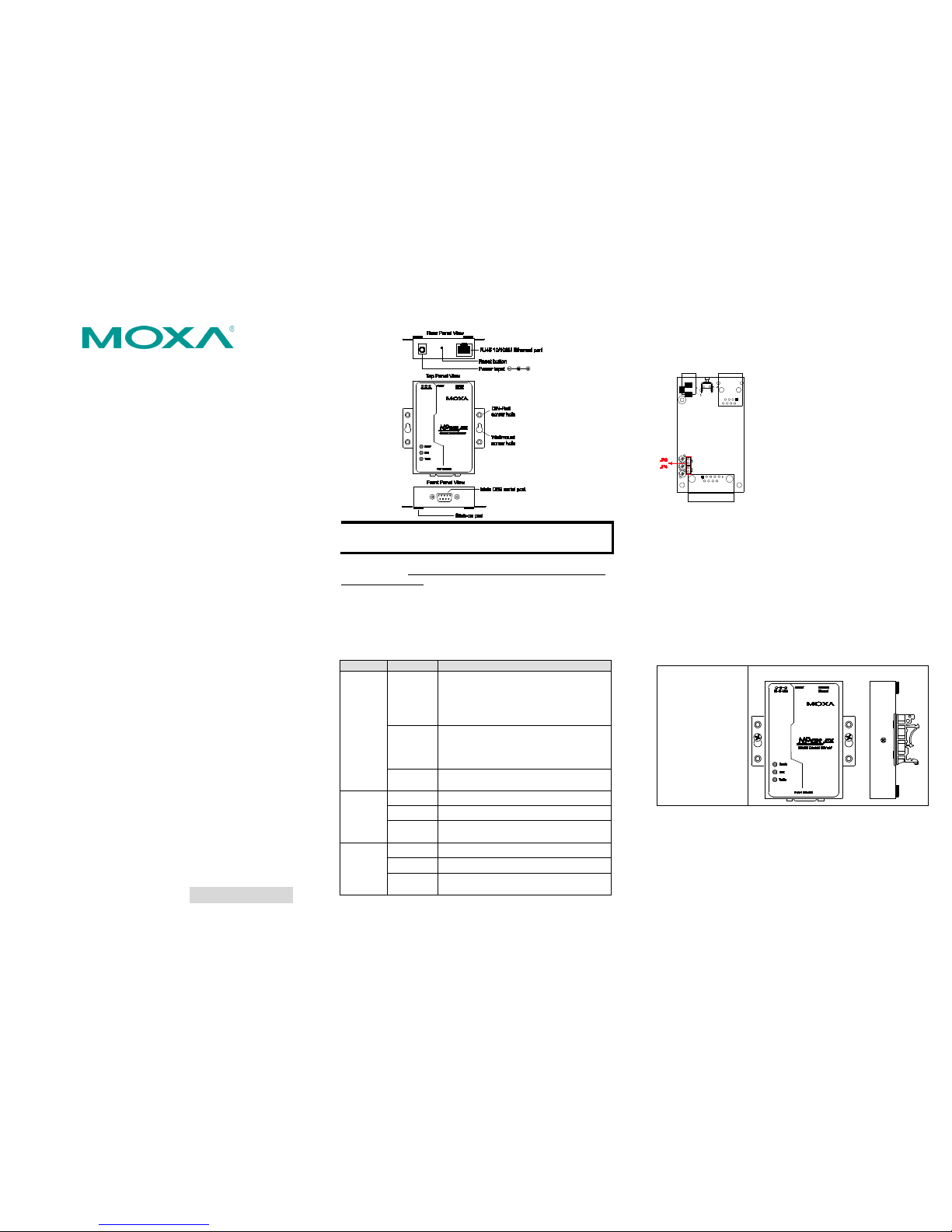
3. Hardware Introduction
As shown in the following figures, NPort 5100 series device servers
have one male DB9 port for transmitting RS-232 (NPort 5110),
RS-422/485 (NPort 5130), or RS-232/422/485 (NPort 5150) serial
data.
NOTE The NPort 5110, NPort 5130, and NPort 5150 have the
same form factor.
Reset Button—Press the Reset button continuously for 5 sec to
load factory defaults: Use a pointed object, such as a straightened
paper clip or toothpick, to press the reset button. This wi ll cause
the Ready LED to blink on and off. The factory defaults will be
loaded once the Ready LED stops blinking (after about 5 seconds).
At this point, you should release the reset button.
LED Indicators—NPort 5100’s top panel has three LED indicators,
which are descr ibed in the follow ing table.
LED Name
LED Color
LED Function
Ready Red Steady on: Power is on and NPort is
booting up.
Blinking: Indicates an IP conflict, or
DHCP or BOOTP server is not respon ding
properly.
Green Steady on: Power is on and NPort is
functioning normally.
Blinking: The NPort has been located
by NPort Administrator’s Location function
Off
Power is off, or power error condition
exists.
Link
Orange
10 Mbps Ethernet connection.
Green
100 Mbps Ethernet con nection.
Off Ethernet cable is disconnected, or has a
short.
Tx/Rx
Orange
Serial port is re ceiving data.
Green
Serial port is transmitting data.
Off
No data is being transmitted or received
through the serial port.
Adjustable pull high/low resistor for RS-422/485
(150 KΩ or 1 KΩ)
Jumpers are used to set the
pull high/low r esistor values .
The default is 150 KΩ. Short
the jumpers to set this value to
1 KΩ. Do not use the KΩ
setting with RS -232 mode,
since doing so wil l degrade the
RS-232 signals and shorten
the communication distance.
4. Hardware Installation Information
STEP 1: After removing the NPort 5100 series device server from
the box, connect the NPort 5100 series device server to a network.
Use a standard straight-through Ethernet cable to connect to a hub
or switch. When setting up or testing the NPort 5100 series device
server, you might find it convenient to connect directly to your
computer’s Ethernet port. In this case, use a cross-over Ethernet
cable.
STEP 2: Connect the NPort 5100 series device server’s serial port
to a serial devic e.
STEP 3: Connect the power adaptor.
STEP 4: Placement options
In addition to placing
the NPort 5100 on a
desktop or other
horizontal surface,
you may also make
use of the DIN-
Rail or
Wall Mount opt ions,
as illustrated here.
Wall Mount DI N-Rail
5. Software Installation Information
To install NPort Administration Suite, insert the NPort
Document & Softwa re CD into your computer’s CD-ROM dr ive.
Once the NPort Installation CD window opens, click on the
Installation button, and then follow the instructions on the
screen.
Page 2
– 4 – – 5 – – 6 –
www.moxa.com/support
The Americas:
+1-714-528-6777 (toll-free: 1-888-669-2872)
Europe:
+49-89-3 70 03 99-0
Asia-Pacific:
+886-2-8919-1230
China:
+86-21-5258-9955 (toll-free: 800-820-5036)
2011 Moxa Inc., All Rig hts Reser ved
To view detailed information about NPort Administration Suite,
click on the Documents button, and then select “NPort 5100
Series User’s Guid e” to open the pdf version of the user’s guide.
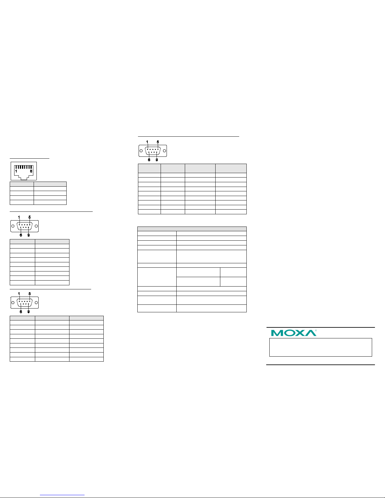
6. Pin Assignments
Ethernet Port Pinouts
Pin Numbe r
Ethernet 1 Tx+ 2 Tx- 3 Rx+ 6 Rx-
NPort 5110—DB9 male ( RS-232) port p inouts
Pin Numbe r
RS-232
1
DCD
2
RxD 3 TxD
4
DTR
5
GND 6 DSR 7 RTS 8 CTS 9 ---
NPort 5130—DB9 male (RS-422/485) port pinouts
Pin Numbe r
RS-422/485 (4W)
RS-485 (2W)
1
TXD-(A)
---
2
TXD+(B)
---
3
RXD+(B)
Data+(B)
4
RXD-(A)
Data-(A)
5
GND
GND
6
---
--- 7 ---
---
8
---
---
9
---
---
NPort 5150—DB9 male (RS-232/422/485) port pinouts
Pin Numbe r RS-232
RS-422/485
(4W)
RS-485 (2W)
1
DCD
TXD-(A)
---
2
RxD
TXD+(B)
---
3
TxD
RXD+(B)
Data+(B)
4
DTR
RXD-(A)
Data-(A)
5
GND
GND
GND
6
DSR
---
---
7
RTS
---
---
8
CTS
---
---
9
---
---
---
7. Specifications
Power Requirements
Power Input
12 to 48 VDC
Power Consumption
NPort 5110: 128.7 mA@12V, 72 mA@24V
NPort 5130: 200 mA@12V, 106 mA@24V
NPort 5150: 200 mA@12V, 106 mA@2 4V
Operating
Temperature
0 to 55°C (32 to 131°F), for standard
models
-40 to 75°C (-40 to 167°F), for -T models
Operating Humid ity
5 to 95% RH
Dimensions
75.2 × 80 × 22 mm
(2.96 × 3.15 × 0.87 in)
including
ears
52 × 80 × 22 m m
(2.05 × 3.15 × 0.89 in)
without ears
Serial Line Protection
15 KV ESD for serial port
Magnetic Isolation
1.5 KV for Etherne t
Power Line Protection
Level 2 Burst (EFT), EN61000-4-4
Level 2 Surge, E N61000-4-5
Regulatory Approvals FCC Class A, CE Class A, UL, LVD
 Loading...