

Page 1

NE-4100 Series User’s Manual
Seventh Edition, September 2006
www.moxa.com/product
MOXA Technologies Co., Ltd.
Tel: +886-2-8919-1230
Fax: +886-2-8919-1231
Web:
MOXA Technical Support
Worldwide:
The Americas
www.moxa.com
support@moxa.com
support@usa.moxa.com
Page 2

NE-4100 Series User’s Manual
The software described in this manual is furnished under a license agreement and may be used only in
accordance with the terms of that agreement.
Copyright Notice
Copyright © 2006 MOXA Technologies Co., Ltd.
All rights reserved.
Reproduction without permi ssi on is pr ohibited.
Trademarks
MOXA is a registered trademark of The MOXA Group.
All other trademarks or registered marks in this manual belong to their respective manufacturers.
Disclaimer
Information in this document is subject to change without notice and does not represent a commitment on the
part of MOXA.
MOXA provides this document “as is,” without warranty of any kind, either expressed or implied, including, but
not limited to, its particular purpose. MOXA reserves the right to make improvements and/or changes to this
manual, or to the products and/or the programs described in this manual, at any time.
Information provided in this manual is intended to be accurate and reliable. However, MOXA assumes no
responsibility for its use or for any infringements on the rights of third parties that may result from its use.
This product may include unintentional technical or typographical errors. Changes are periodically made to th e
information herein to correct such errors, and these changes are incorporated into new editions of the
publication.
Page 3

Table of Contents
Chapter 1. Introduction ...............................................................................................1-1
Overview.............................................................................................................................. 1-2
Package Checklist................................................................................................................. 1-2
Product Features................................................................................................................... 1-2
Product Specifications.......................................................................................................... 1-3
Chapter 2. Panel Layout and Pin Assignments ........................................................2-1
NE-4100T, NE-4100-ST....................................................................................................... 2-2
Panel Layout................................................................................................................. 2-2
NE-4100-ST LED Indicators........................................................................................ 2-2
Pin Assignments........................................................................................................... 2-3
Block Diagrams............................................................................................................ 2-4
NE-4110S, NE-4110A, NE-4110-ST.................................................................................... 2-5
Panel Layout................................................................................................................. 2-5
NE-4110-ST LED Indicators........................................................................................ 2-6
Pin Assignments........................................................................................................... 2-6
Block Diagrams............................................................................................................ 2-8
NE-4120S, NE-4120A, NE-4120-ST................................................................................... 2-9
Panel Layout................................................................................................................. 2-9
NE-4120-ST LED Indicators...................................................................................... 2-10
Pin Assignments......................................................................................................... 2-11
Block Diagrams.......................................................................................................... 2-12
Chapter 3. Getting Started ..........................................................................................3-1
Wiring Precautions............................................................................................................... 3-2
Installing the NE-4100T onto the NE-4100-ST.................................................................... 3-3
Installing the NE-4110S, NE-4110A onto the NE-4110-ST................................................. 3-3
Installing the NE-4120S, NE-4120A onto the NE-4120-ST................................................. 3-4
Selecting the Serial Interface................................................................................................ 3-4
Circuit Pad for External Connection..................................................................................... 3-5
Connecting the Power........................................................................................................... 3-5
Connecting to the Network................................................................................................... 3-6
Connecting to a Serial Device.............................................................................................. 3-6
Digital I/O Channel Settings................................................................................................. 3-6
Digital Output LED Circuit Design.............................................................................. 3-8
Chapter 4. Choosing the Proper Operation Mode ....................................................4-1
Overview.............................................................................................................................. 4-2
TCP Server Mode................................................................................................................. 4-2
TCP Client Mode.................................................................................................................. 4-3
UDP Mode............................................................................................................................ 4-3
Real COM Mode .................................................................................................................. 4-4
Chapter 5. Initial IP Address Configuration...............................................................5-1
Static vs. Dynamic IP Address.............................................................................................. 5-2
Factory Default IP Address................................................................................................... 5-2
NE-4100 Series A dministration Suite................................................................................... 5-2
ARP...................................................................................................................................... 5-2
Telnet Console...................................................................................................................... 5-3
Serial Console (19200, n, 8, 1)............................................................................................. 5-5
Page 4

Chapter 6. Web Console Configuration.....................................................................6-1
Opening Your Browser ......................................................................................................... 6-2
Web Console Navigation...................................................................................................... 6-3
Basic Settings ....................................................................................................................... 6-4
Network Settings.................................................................................................................. 6-5
Serial Settings....................................................................................................................... 6-8
Operating Settings.............................................................................................................. 6-10
TCP Server Mode....................................................................................................... 6-10
Real COM Mode ........................................................................................................ 6-12
TCP Client Mode........................................................................................................ 6-15
UDP Mode.................................................................................................................. 6-18
Accessible IP Settings.........................................................................................................6-20
Auto W a rning Settings........................................................................................................ 6-21
E-mail and SNMP Trap.............................................................................................. 6-21
Event Type.................................................................................................................. 6-22
Digital IO............................................................................................................................ 6-23
DIO Settings............................................................................................................... 6-23
DIO Monitor............................................................................................................... 6-24
Serial Command Mode....................................................................................................... 6-24
Change Password................................................................................................................ 6-24
Load Factory Defaults........................................................................................................ 6-25
Save/Restart........................................................................................................................ 6-25
Chapter 7. Network Enabler Administrator ...............................................................7-1
Overview.............................................................................................................................. 7-2
Installing Network Enabler Administrator............................................................................ 7-2
Network Enabler Administrator Navigation......................................................................... 7-4
Configuration Functions....................................................................................................... 7-5
Broadcast Search .......................................................................................................... 7-5
Specify by IP Address .................................................................................................. 7-6
Locate........................................................................................................................... 7-6
Unlock .......................................................................................................................... 7-7
Configure...................................................................................................................... 7-9
Upgrade Firmware ...................................................................................................... 7-11
Import and Export Configuration ............................................................................... 7-12
Monitor Functions.............................................................................................................. 7-13
Add and Remove Target............................................................................................. 7-13
Load Configured COM Port....................................................................................... 7-14
Settings....................................................................................................................... 7-15
Go and Stop................................................................................................................ 7-16
Port Monitor Functions....................................................................................................... 7-18
COM Mapping Functions................................................................................................... 7-18
Add and Remove Target............................................................................................. 7-18
COM Settings............................................................................................................. 7-19
Enable and Disable..................................................................................................... 7-21
Apply and Discard Change ......................................................................................... 7-21
Import and Export COM Mapping............................................................................. 7-21
IP Address Report Functions .............................................................................................. 7-21
Chapter 8. Linux and UNIX Configuration .................................................................8-1
Linux Real TTY Drivers....................................................................................................... 8-2
Basic Procedures........................................................................................................... 8-2
Page 5

Hardware Setup ............................................................................................................ 8-2
Installing Linux Real TTY Driver Files .......................................................................8-2
Mapping TTY Ports...................................................................................................... 8-3
Removing Mapped TTY Ports......................................................................................8-3
Removing Linux Driver Files....................................................................................... 8-4
UNIX Fixed TTY Driver...................................................................................................... 8-4
Installing the UNIX Driver........................................................................................... 8-4
Configuring the UNIX Driver ...................................................................................... 8-5
Chapter 9. Serial Command Mode..............................................................................9-1
Overview.............................................................................................................................. 9-2
Serial Command Format and Command Set........................................................................ 9-2
Command Structure...................................................................................................... 9-2
Reply Structure............................................................................................................. 9-3
OP Codes and Parameters............................................................................................. 9-3
Operation Flow Chart........................................................................................................... 9-9
Configuring Trigger Type..................................................................................................... 9-9
Network Enabler Administrator..................................................................................9-10
Telnet Console............................................................................................................ 9-12
Web Console ..............................................................................................................9-13
Serial Console............................................................................................................. 9-13
Entering Serial Command Mode........................................................................................ 9-14
Trigger Type............................................................................................................... 9-14
Serial Port Parameters................................................................................................. 9-14
Comments................................................................................................................... 9-15
Exiting Serial Command Mode.......................................................................................... 9-15
Determining the Active Mode ............................................................................................9-16
Serial Command Examples ................................................................................................ 9-17
Example 1: Get Model Name Using HW Trigger...................................................... 9-17
Example 2: Change IP Address Using HW Trigger................................................... 9-17
Example 3: Get IP Mode Using SW Trigger.............................................................. 9-18
Example 4: Change TCP Port Number Using SW Trigger......................................... 9-18
Appendix A. Well Known Port Numbers ......................................................................A-1
Appendix B. NECI Library..............................................................................................B-1
Appendix C. Auto IP Report Protocol........................................................................... C-1
IP Address Report Structure .................................................................................................C-2
Hardware and AP ID.............................................................................................................C-2
Example................................................................................................................................C-2
Appendix D. DIO Commands ........................................................................................D-1
Overview............................................................................................................................. D-1
C Code Example .......................................................................................................... D-1
Read Single DIO.................................................................................................................. D-2
Command .................................................................................................................... D-2
Response...................................................................................................................... D-2
C Code Example .......................................................................................................... D-2
Write Single DIO................................................................................................................. D-3
Command .................................................................................................................... D-3
Response...................................................................................................................... D-3
C Code Example:......................................................................................................... D-3
Page 6

Read Multiple DIO.............................................................................................................. D-4
Command .................................................................................................................... D-4
Response...................................................................................................................... D-4
C Code Example:......................................................................................................... D-5
Write Multiple DIO............................................................................................................. D-5
Command .................................................................................................................... D-5
Response...................................................................................................................... D-6
C Code Example:......................................................................................................... D-7
Appendix E. SNMP Agent with MIB II & RS-232 Like Group ...................................... E-1
Appendix F. Service Information...................................................................................F-1
MOXA Internet Services......................................................................................................F-2
Technical Support E-mail Address...............................................................................F-2
Website for Product Information.................................................................................. F-2
Problem Report Form........................................................................................................... F-3
Product Return Procedure.....................................................................................................F-4
Page 7

1
1
Chapter 1. Introduction
The NE-4100 Series embedded device server is a line of compact modules that act as network
enablers. NE-4100 Series modules can be installed in or on a serial device to connect it to an
Ethernet network, allowing you to gain network access to any electronic device that has a serial
port. All NE-4100 Series modules come equipped with built-in TCP/IP protocols for fast
integration, saving you time and energy on programming.
The following topics are covered in this chapter.
Overview
Package Checklist
Product Features
Product Specifications
Page 8

NE-4100 Series User’s Manual Introduction
Overview
NE-4100 Series modules are a type of embedded device server or network enabler. An NE-4100
Series module may be installed in or attached to a serial device to make it accessible from a
network. There are three types of module offered: drop-in (NE-4100T), RJ45 (NE-4110S,
NE-4110A), and pin header (NE-4120S, NE-4120A). The last letter of the model number indicates
the serial signal supported by the module. T indicates a TTL connector, S indicates an RS-232
connector, and A indicates an RS-422/485 connector. Each module includes 4 digital input/output
channels, also known as DIO channels or GPIO channels.
NE-4100 Series modules are very compact—less than half the size of a credit card. At such a small
size, they can be installed into almost any serial device. Each NE-4100 Series module also comes
with a built-in TCP/IP stack for fast integration. Engineers can spend less time on TCP/IP
programming, and focus more on developing other major features, thereby shortening your
product’s time to market. Modules may be easily configured with a user-friendly Windows utility,
web browser, serial console, or Telnet console. In addition, a Windows-based NECI (Network
Enabler Configuration Interface) library is available to help you develop your own Windows
utilities.
Each module comes with a complete development kit containing an evaluation board, documents,
sample code, cables, and accessories.
Package Checklist
z 1 NE-4100 Series module
z 1 NE-4100-ST (the evaluation board )
z NE-4100 Series documentation & software CD
z 1 universal power adaptor
z 2 power cords
z 1 null modem cable
z 1 cross-over Ethernet cable
z Warranty statement
z Quick Installation Guide
NOTE: Please notify your sales representative if any of the above items is missing or damaged.
Product Features
All NE-4100 Series modules have the following features:
z 10/100 Mbps auto-sensing Ethernet interface
z Compact size and ready-to-go design (NE-4100T measures 45 × 36 mm, NE-4110/4120
measure 57 × 40 mm)
z Built-in TCP/IP firmware for fast integration
z TCP Server, TCP Client, UDP, Real COM driver operation modes
z Low power consumption (1.5W)
z Multiple user-friendly configuration options
z 4 dedicated digital input/output (DIO) channels for user applications
z Software reset
1-2
Page 9

NE-4100 Series User’s Manual Introduction
Product Specifications
System
CPU 16-bit MCU
RAM 1 MB
Flash 2 MB
LAN
Ethernet
Protection built-in transformer with 1.5 KV magnetic isolation
Serial
Interface TTL
Port Type pin header RJ45 pin header
Signals
Serial Communication Parameters
NE-4100T NE-4110S, NE-4110A NE-4120S, NE-4120A
10/100 Mbps, pin
headers
TTL, RS-232: TxD, RxD, RTS, CTS, DTR, DSR, DCD, GND
RS-422: TxD+, TxD-, RxD+, RxD-, GND
RS-485 (4-wire): TxD+, TxD-, RxD+, RxD-, GND
10/100 Mbps, RJ45 10/100 Mbps, pin headers
RS-232 (NE-4110S)
RS-422/485 (NE-4110A)
RS-485 (2-wire): Data+, Data-, GND
RS-232 (NE-4120S)
RS-422/485 (NE-4120A)
Parity None, Even, Odd, Space, Mark
Data Bits 5, 6, 7, 8
Stop Bit 1, 1.5, 2
Flow Control RTS/CTS, XON/XOFF
Transmission
Speed
Software Features
Protocols ICMP, ARP, IP, TCP, UDP, DHCP, HTTP, SNMP, SMTP
Operating
Mode
Utilities NE utility for Windows 95/98/ME/NT/2000/XP/2003(x64)/XP(x64)
Configuration web browser, serial console, Telnet console, or Windows utility
Power Requirements
Power Input 5 VDC
Power
Consumption
50 bps to 115.2 Kbps for PCB V1.x, 110 bps to 230.4 Kbps for PCB V2.x
TCP Server, TCP Client, UDP, Real COM mode
290 mA @ 5 VDC (Max.)
1-3
Page 10

NE-4100 Series User’s Manual Introduction
Environmental
Operating
Temperature
Storage
Temperature
Regulatory Approvals
EMC FCC Class A, CE Class A
Warranty 5 years
NE-4100T NE-4110S, NE-4110A NE-4120S, NE-4120A
0°C to 70°C (32°F to 158°F), 5% to 95%RH
-20°C to 85°C (-4°F to 185°F), 5% to 95%RH
1-4
Page 11

2
2
Chapter 2. Panel Layout and Pin Assignments
This chapter includes information about the panel layouts and p in assignments for NE-4100 Series
modules. The layouts and reference circuit diagrams for the evaluation boards are also covered.
The evaluation boards are used for evaluation and development of applications for NE-4100 Series
modules.
The following topics are covered in this chapter:
NE-4100T, NE-4100-ST
¾ Panel Layout
¾ NE-4100-ST LED Indicators
¾ Pin Assignments
¾ Block Diagrams
NE-4110S, NE-4110A, NE-4110-ST
¾ Panel Layout
¾ NE-4110-ST LED Indicators
¾ Pin Assignments
¾ Block Diagrams
NE-4120S, NE-4120A, NE-4120-ST
¾ Panel Layout
¾ NE-4120-ST LED Indicators
¾ Pin Assignments
¾ Block Diagrams
Page 12
NE-4100 Series User’s Manual Panel Layout and Pin Assignments
N
NE-4100T, NE-4100-ST
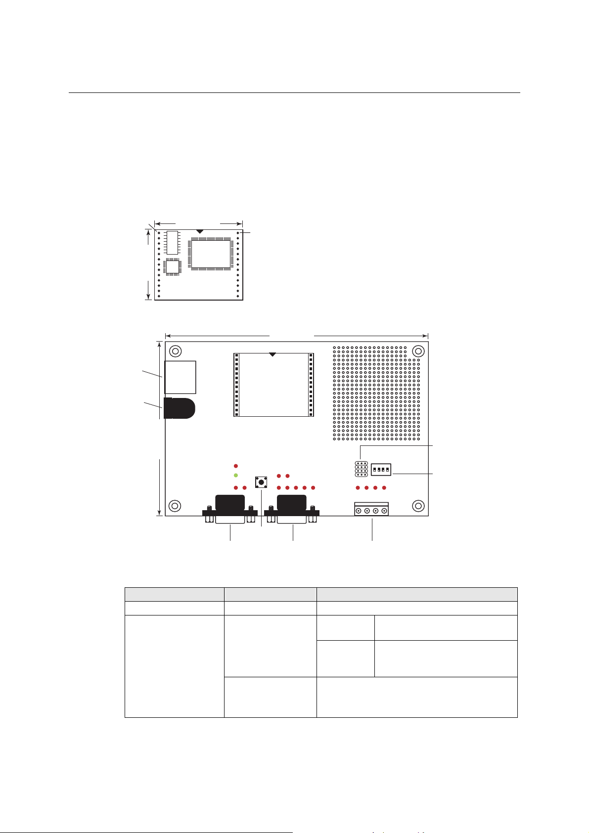
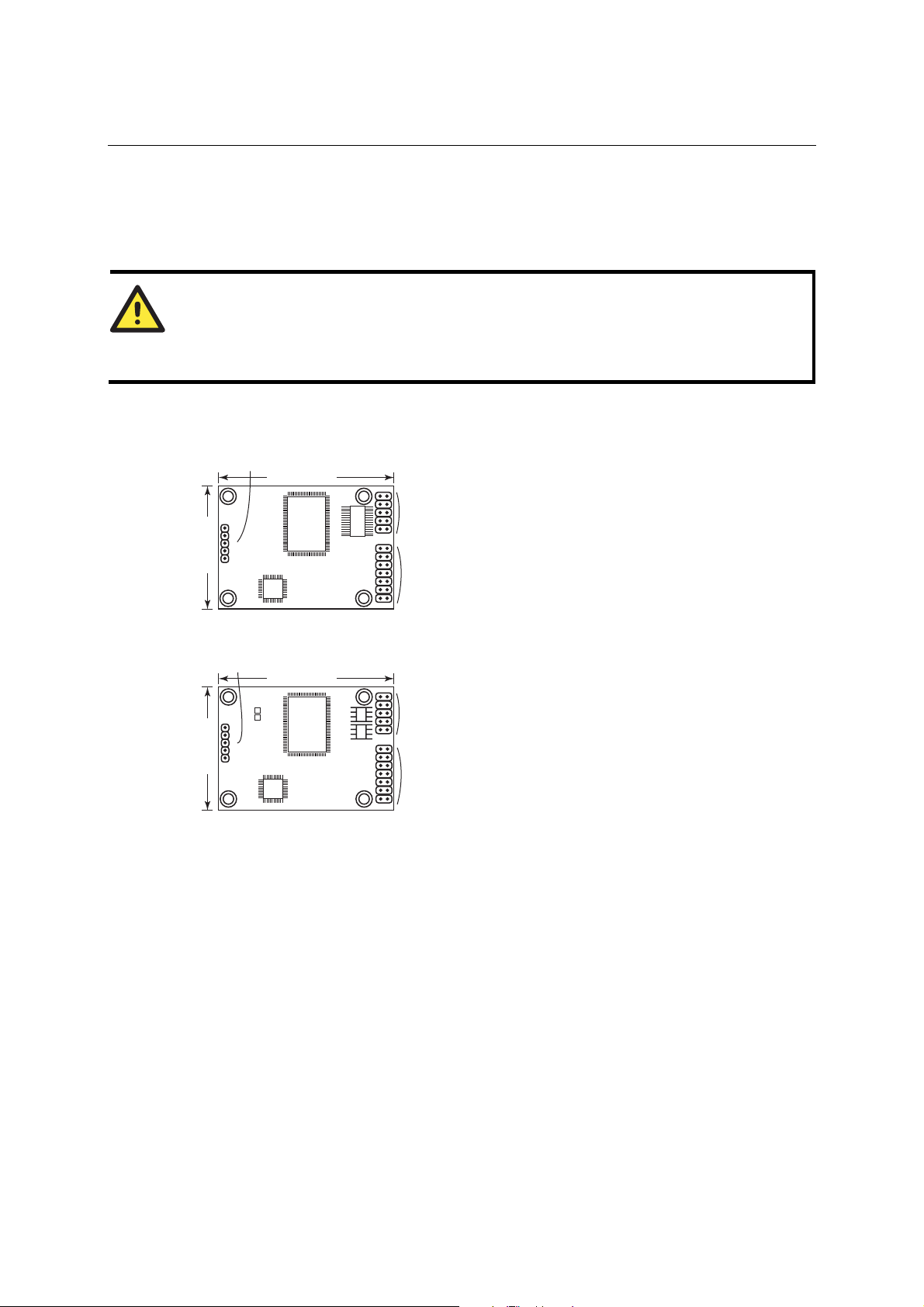
The NE-4100T is a TTL-to-Et her net dr op -in module. It measures 45 × 36 mm, and has a
dual-in-line, 26-pin design, making it easy to integrate with your serial devices. The NE-4100-ST
is the evaluation board for testing NE-4100T modules and developing your own applications.
Panel Layout
NE-4100T
Pin #1
36.00 mm
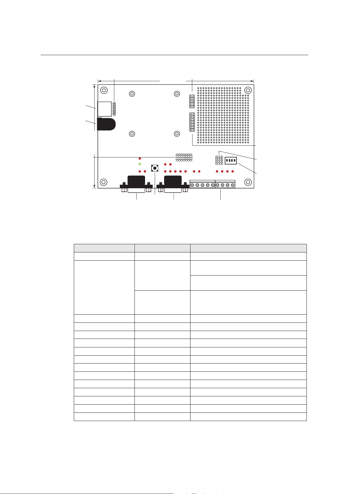
NE-4100-ST
Ethernet
Port
45.00 mm
Pin #14
149.00 mm
Power
Jack
99.00 mm
NE-4100-ST LED Indicators
LED Name LED Color LED Function
Power red Indicates the power is on.
Ready
Reset Button
Serial Port (RS-232)Debug Serial COM Port DI/O Terminal Block
Steady on:
green
Blinking:
y Power is off, or power error condition exists.
steady off
y IP address cannot be found in DHCP mode.
DI/O Selector
Jumpers
ON
DIP
1234
DI/O Signal
Setting
Switches
Power is on and NE-4100T is
functioning normally.
NE-4100T has been located by
etwork Enabler’s Administrator’s
Location function.
y IP address conflict.
2-2
Page 13

NE-4100 Series User’s Manual Panel Layout and Pin Assignments
LED Name LED Color LED Function
DIO0 red Indicates that DIO is in “low” (0) status.
DIO1 red Indicates that DIO is in “low” (0) status.
DIO2 red Indicates that DIO is in “low” (0) status.
DIO3 red Indicates that DIO is in “low” (0) status.
TXD0 red Indicates that TXD0 has a signal.
RXD0 red Indicates that RXD0 has a signal.
DTR0 red Indicates that DTR0 has a signal.
CTS0 red Indicates that CTS0 has a signal.
DSR0 red Indicates that DSR0 has a signal.
DCD0 red Indicates that DCD0 has a signal.
RTS0 red Indicates that RTS0 has a signal.
TXD1 red Indicates that TXD1 has a signal.
RXD1 red Indicates that RXD1 has a signal.
Pin Assignments
NE-4100T
Pin Signal Pin Signal
1 ETx+ 14 PIO0
2 ETx- 15 PIO1
3 ERx+ 16 PIO2
4 ERx- 17 PIO3
5 10M LED 18 100M LED
6 TXD 19 DCD
7 RXD 20 DSR
8 RTS 21 DTR
9 CTS 22 GND
10 Reset 23 Ready LED
11 GND 24 +5V
12 GND 25 +5V
13 TXD1* 26 RXD1*
*Pins 13 and 26 control the NE-4100-ST Debug Serial COM Port’s TXD and RXD signals. The
location of the Debug Serial COM Port is shown on the pr evi o us page. This port is not needed
during normal operation. However, if the network fails and you need to configu re your NE-4100T,
you may connect the Debug Serial COM Port, and then use the serial console to config ure your
NE-4100T.
ATTENTION
NE-4100T Ethernet Signals: ETx+, ETx-, ERx+, ERx Serial Signals: TXD, RXD, RTS, CTS, DCD, DSR, DTR
LED Controls: 10M LED, 100M LED, Ready LED
2-3
Page 14
NE-4100 Series User’s Manual Panel Layout and Pin Assignments
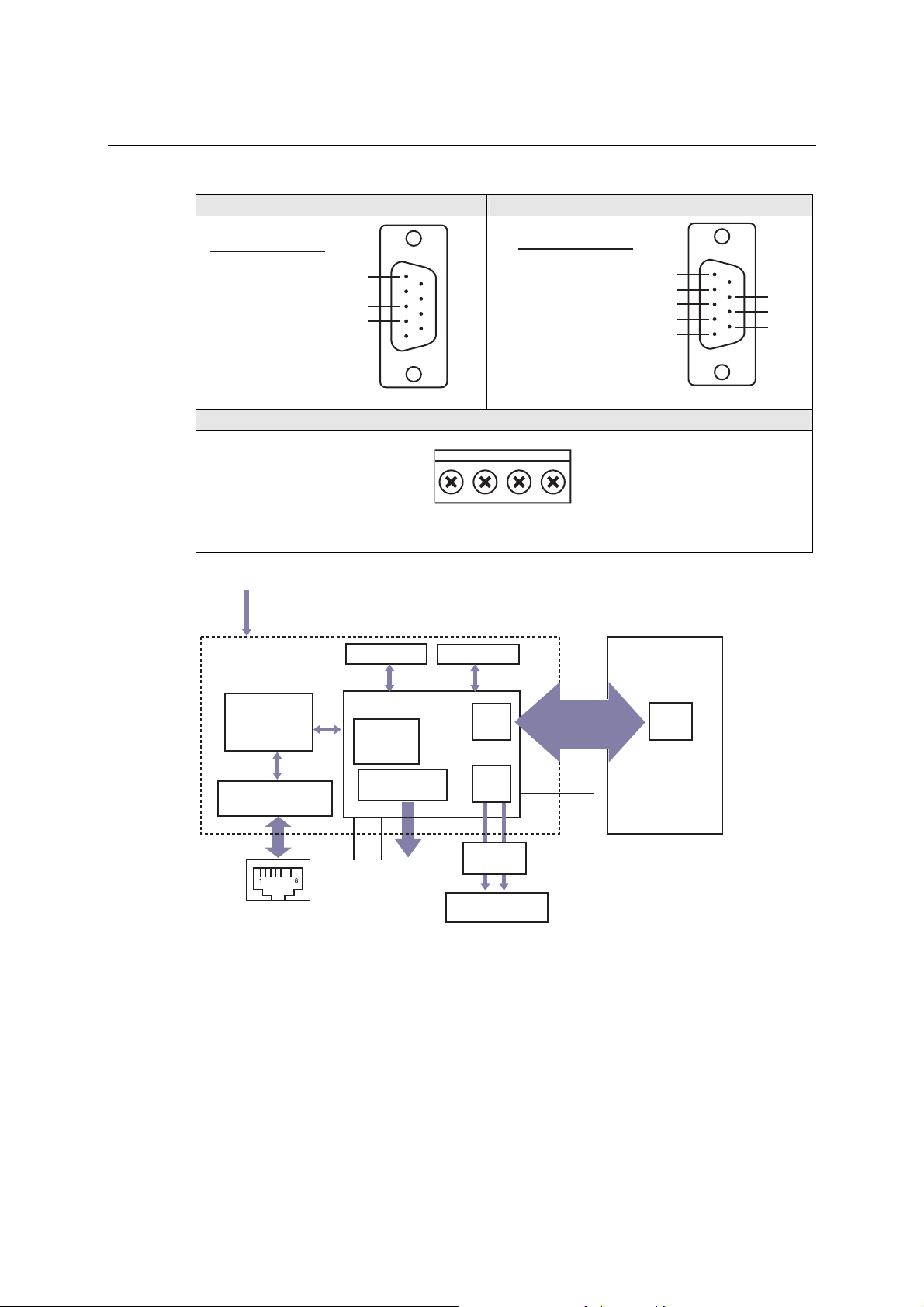
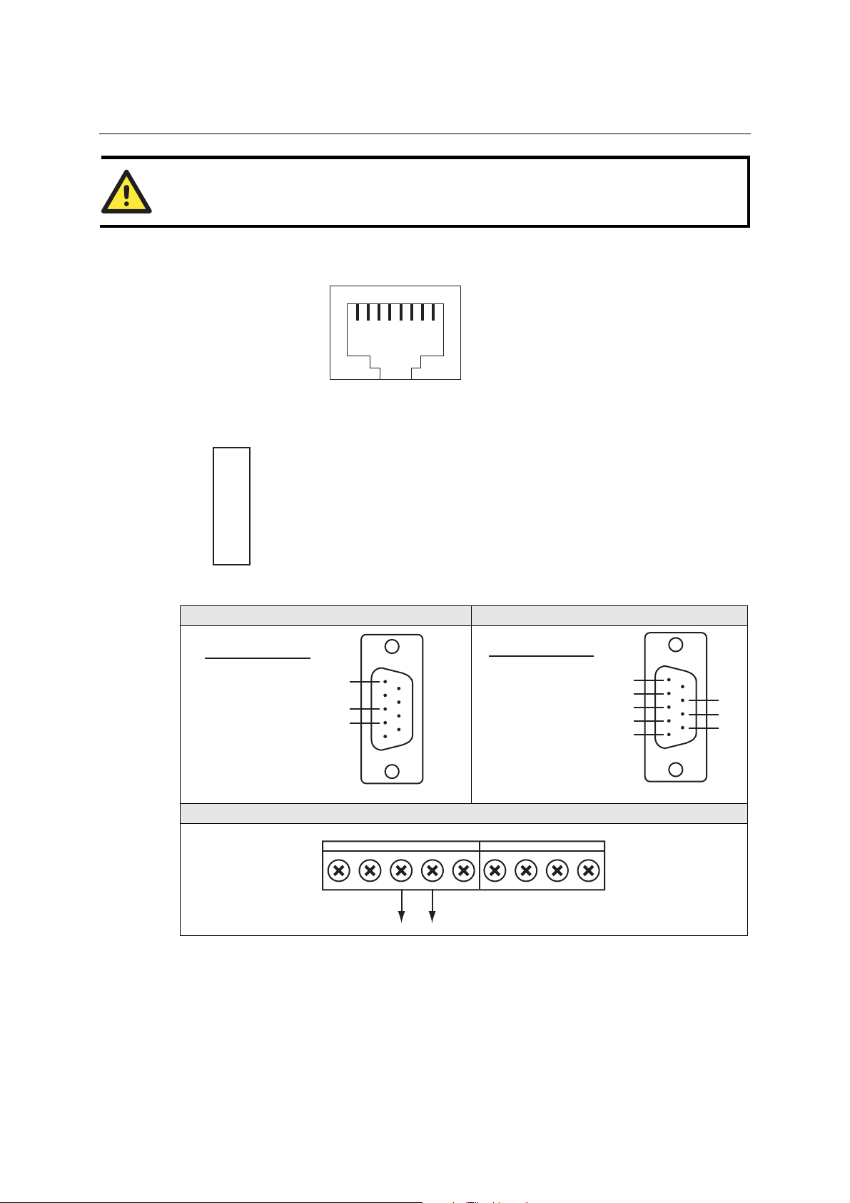
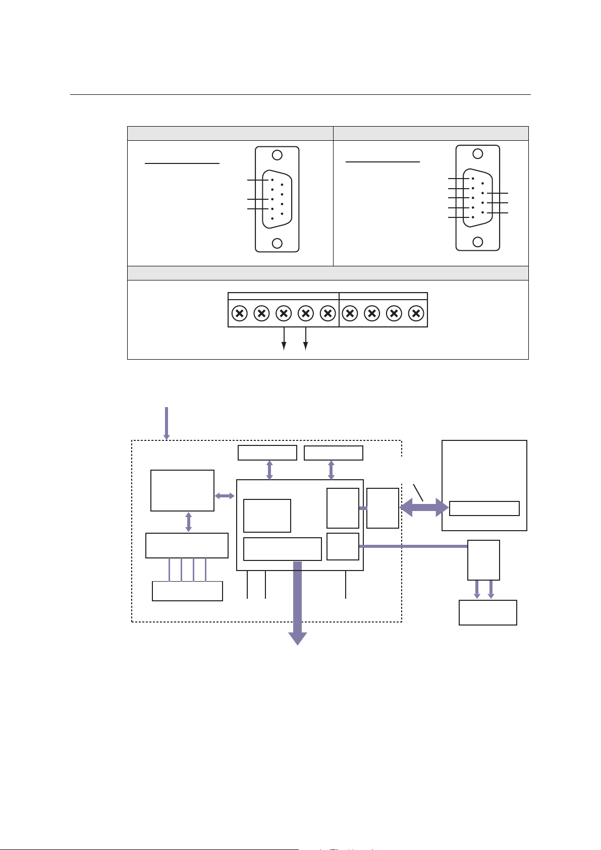
NE-4100-ST Serial Port Pinouts (DB9 Male)
Debug Serial Port for Serial Console RS-232 Port for Connecting Serial Devices
Pin
Signal
Pin
Signal
2
3
5
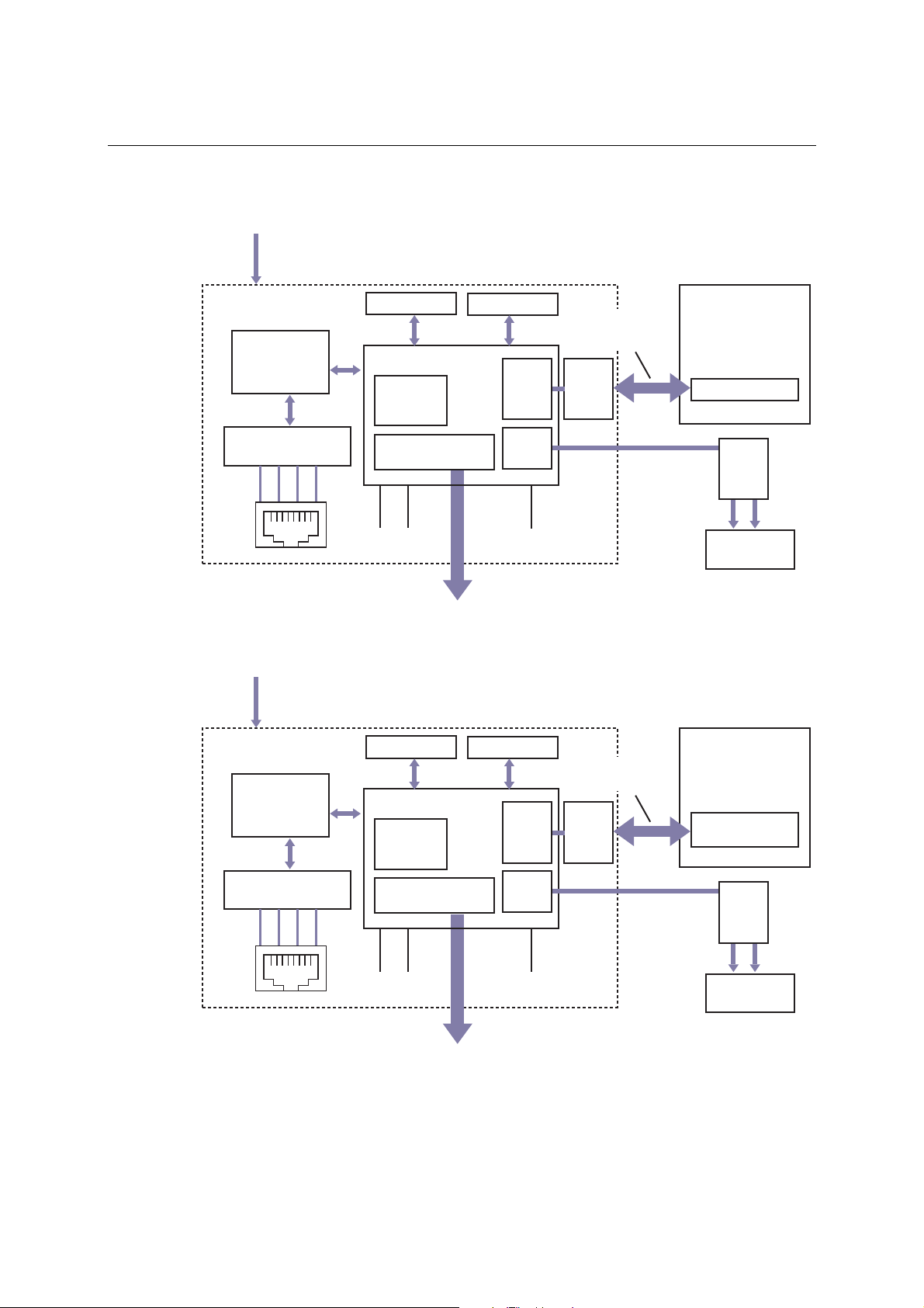
Block Diagrams
+5 VDC
10/100M
Ethernet PHY
RXD
TXD
GND
5
3
2
DIO Terminal Block
D0 D1 D2 D3
1 MB SDRAM 2 MB Flash
80186 CPU
UART0
MAC
1
2
3
4
5
6
7
8
TTL Serial data
(Tx, Rx, RTS, CTS,
DTR, DSR, DCD)
DCD
RXD
TXD
DTR
GND
DSR
RTS
CTS
Customer's Device
UART
5
4
3
2
1
8
7
6
Transformer
1.5 KV Isolation
RJ45
10M
LED
GPIO Port
PIO0 - PIO3
100M
LED
UART1
Line
Driver
Tx Rx
Serial Console
interface
2-4
Ready
LED
Page 15
NE-4100 Series User’s Manual Panel Layout and Pin Assignments
NE-4110S, NE-4110A, NE-4110-ST
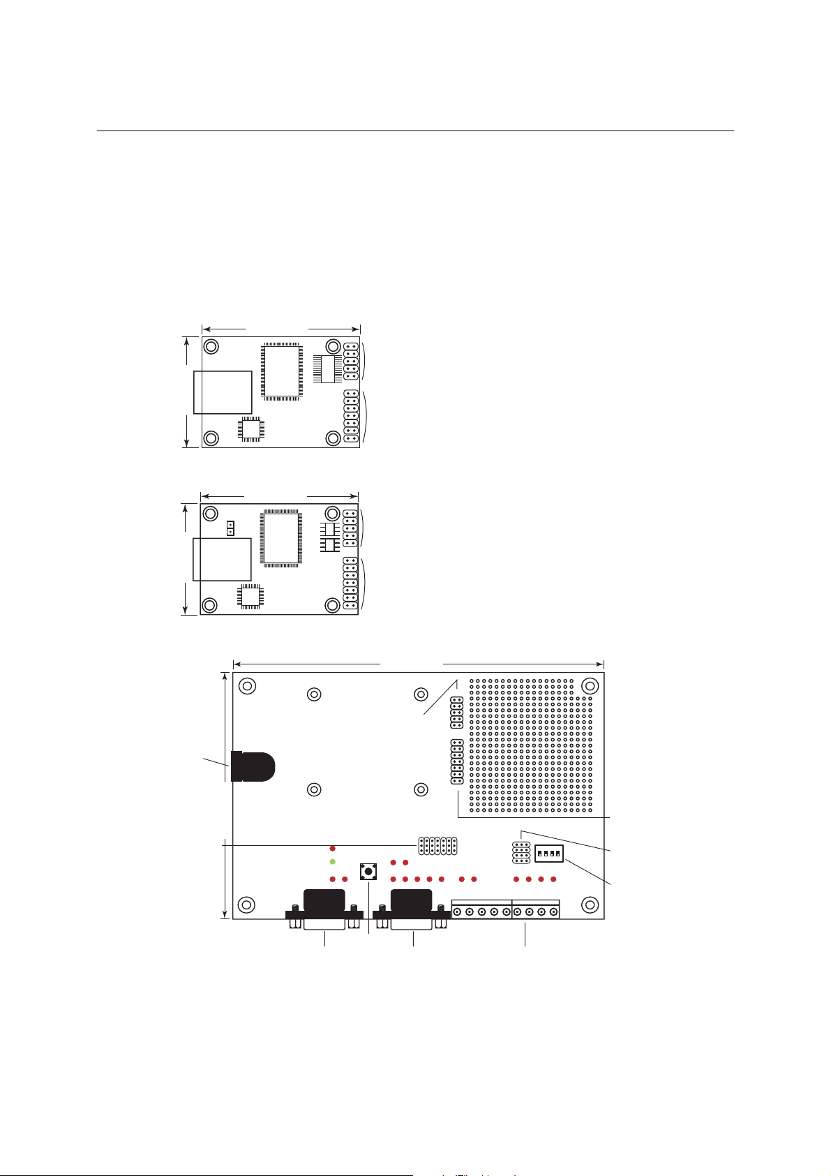
The NE-4110S is an RS-232-to-Ethernet server, and the NE-4110A is an RS-422/485-to-Ethernet
server. Both models use an RJ45 connection and measure 57 × 40 mm. The NE-4110-ST is the
evaluation board for testing NE-4100S and NE-4110A modules and developing your own
applications.
Panel Layout
NE-4110S
57.00 mm
40.00 mm
NE-4110A
57.00 mm
JP2
40.00 mm
1
2
J1
9
10
1
2
J2
13
14
1
2
J1
9
10
1
2
J2
13
14
NE-4110-ST
149.00 mm
12
Jumper 9 (J9)
Power
Jack
99.00 mm
Interface
Selector
Jumpers
Reset Button
Serial Port (RS-232)Debug Serial COM Port DI/O Terminal Block
* JP2 is used to select RS-232 or RS-422/485 operation. Use the RS-232 position for RS-232
operation (NE-4110S); use the RS-485 position for RS-422 or RS-485 operation (NE-4110A).
910
12
13 14
ON
DIP
1234
Jumper 10
(J10)
DI/O Selector
Jumpers
DI/O Signal
Setting
Switches
2-5
Page 16
NE-4100 Series User’s Manual Panel Layout and Pin Assignments
NE-4110-ST LED Indicators
LED Name LED Color LED Function
Power red Indicates the power is on.
Steady on: Power is on and NE-4110 is
green
Ready
steady off
DIO0 red Indicates that DIO is in “low” (0) status.
DIO1 red Indicates that DIO is in “low” (0) status.
DIO2 red Indicates that DIO is in “low” (0) status.
DIO3 red Indicates that DIO is in “low” (0) status.
TXD0 red Indicates that TXD0 has a signal.
RXD0 red Indicates that RXD0 has a signal.
DTR0 red Indicates that DTR0 has a signal.
CTS0 red Indicates that CTS0 has a signal.
DSR0 red Indicates that DSR0 has a signal.
DCD0 red Indicates that DCD0 has a signal.
RTS0 red Indicates that RTS0 has a signal.
TXD1 red Indicates that TXD1 has a signal.
RXD1 red Indicates that RXD1 has a signal.
functioning normally.
Blinking: NE-4110 has been located by
Network Enabler Administrator.
y Power is off, or power error condition exists.
y IP address cannot be found in DHCP mode.
y IP address conflict.
Pin Assignments
NE-4110S Serial Header Pinouts (J1)
9
10
NC
7
8
CTS0
5
6
DSR0
3
4
DTR0
1
2
RxD0
NE-4110A Serial Header Pinouts (J1)
9
10
NC
7
8
NC
5
6
NC
3
4
RxD-
1
2
TxD+
ATTENTION
The symbols “B” and “A” are often used in place of “+” and “-”, respectively.
NC
RTS0
GND
TxD0
DCD0
NC
NC
GND
RxD+
TxD-
2-6
Page 17
NE-4100 Series User’s Manual Panel Layout and Pin Assignments
ATTENTION
For the 2-wire RS-485 interface, pin 3 is for Data+ (B) and pin 4 is for Data- (A).
NE-4110S and NE-4110A Ethernet Port Pinouts
Pin Signal
1
2
3
6
Tx+
TxRx+
Rx-
1
RJ45 Port
8
NE-4110S and NE-4110A DIO and LED Header Pinouts (J2)
14
10
8
6
4
2
VCC(+5V)
111312
VCC(+5V)
10M_LED
9
100M_LED
7
Ready_LED
5
Reset
3
RxD1
1
GND
GND
DIO0
DIO1
DIO2
DIO3
TxD1
NE-4110-ST Pinouts
Debug Serial Port for Serial Console RS-232 Port for Serial Devices
Pin
2
3
5
Signal
RXD
TXD
GND
5
3
2
Serial and DIO Terminal Blocks
TXD+ D0 D1 D2 D3TXD- RXD+ RXD-
SGND
Pin
1
2
3
4
5
6
7
8
Signal
DCD
RXD
TXD
DTR
GND
DSR
RTS
CTS
5
4
3
2
1
8
7
6
Data+ Data-
2-7
Page 18
NE-4100 Series User’s Manual Panel Layout and Pin Assignments
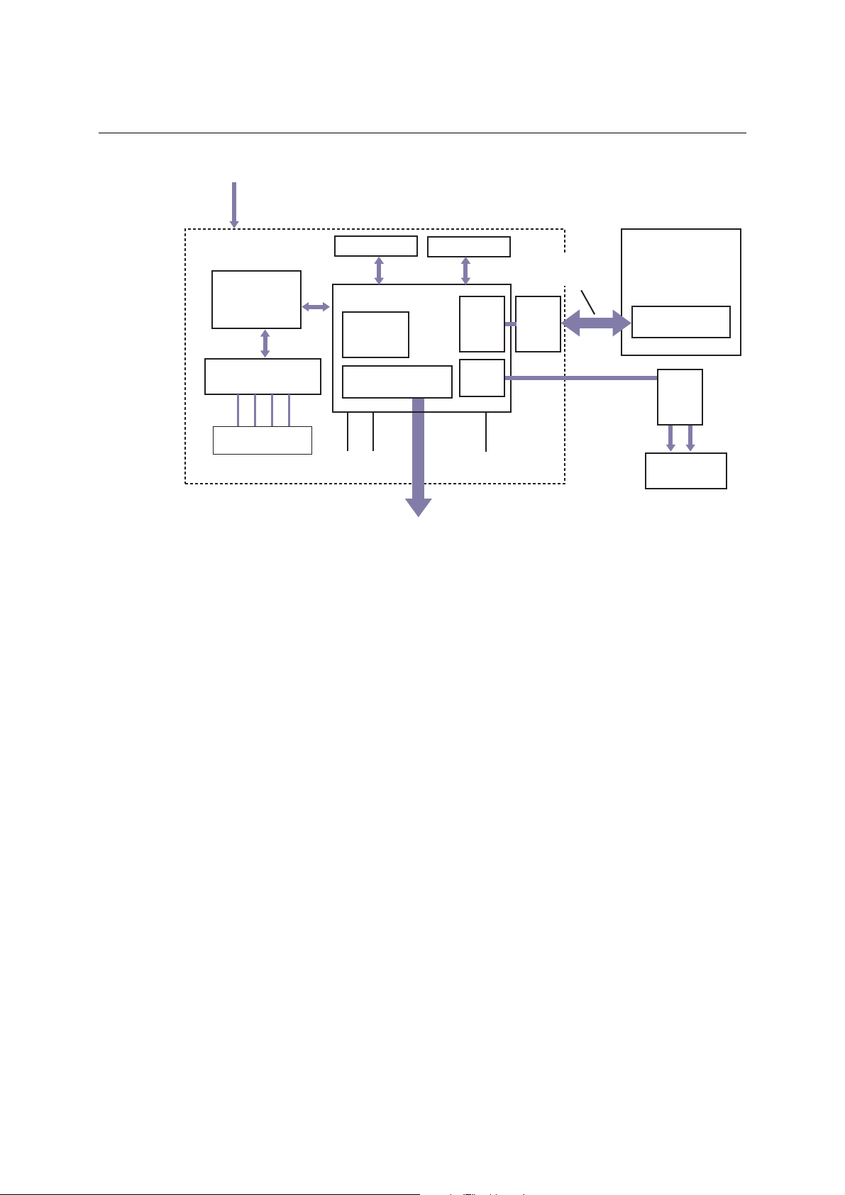
Block Diagrams
NE-4110S Block Diagram
+5 VDC
1 MB SDRAM
10/100 M
Ethernet PHY
Transformer
1.5 KV isolation
Tx+ Tx- Rx-Rx+
18
RJ45
10M
LED
NE-4110A Block Diagram
+5 VDC
1 MB SDRAM
10/100 M
Ethernet PHY
80186 CPU
MAC
GPIO Port
PIO0 - PIO3
100M
LED
80186 CPU
MAC
2 MB Flash
UART0
UART1
Ready
LED
2 MB Flash
UART0
Serial data
(Tx, Rx, RTS, CTS,
DTR, DSR, DCD)
Line
Driver
RS-422/485
Signal
Line
Driver
Customer's device
RS-232 interface
Line
Driver
Tx Rx
Serial console
interface
Customer's device
RS-422/485
interface
Transformer
1.5 KV isolation
Tx+ Tx- Rx-Rx+
18
RJ45
10M
LED
GPIO Port
PIO0 - PIO3
100M
LED
2-8
UART1
Ready
LED
Line
Driver
Tx Rx
Serial console
interface
Page 19
NE-4100 Series User’s Manual Panel Layout and Pin Assignments
NE-4120S, NE-4120A, NE-4120-ST
The NE-4120S is an RS-232-to-Ethernet server, and the NE-4120A is an RS-422/485-to-Ethernet
server. Both models use pin headers instead of RJ45 connectors. The NE-4120-ST is the evaluation
board for testing NE-4120S and NE-4120A modules and developing your own applications.
ATTENTION
The NE-4120-ST is the same board as the NE-4110-ST but with an RJ45 jack and pin headers. If
your evaluation board has “NE-4110-ST” printed on the board but has the RJ45 jack and pin
headers, you have the NE-4120-ST board.
Panel Layout
NE-4120S
J3
5
4
3
2
1
40.00 mm
57.00 mm
1
2
J1
9
10
1
2
J2
NE-4120A
J3
JP2
5
4
3
2
1
40.00 mm
57.00 mm
13
14
1
2
J1
9
10
1
2
J2
13
14
2-9
Page 20
NE-4100 Series User’s Manual Panel Layout and Pin Assignments
NE-4120-ST
Jumper 9 (J9)Jumper 7 (J7)
12
910
12
13 14
Ethernet
Port
Power
Jack
149.00 mm
5
3
3
2
1
99.00 mm
Interface
Selector
Jumpers
* JP2 is used to select RS-232 or RS-422/485 operation. Use the RS-232 position for RS-232
operation (NE-4120S); use the RS-485 position for RS-422 or RS-485 operation (NE-4120A).
NE-4120-ST LED Indicators
LED Name LED Color LED Function
Power red Indicates the power is on.
Ready
DIO0 red Indicates that DIO is in “low” (0) status.
DIO1 red Indicates that DIO is in “low” (0) status.
DIO2 red Indicates that DIO is in “low” (0) status.
DIO3 red Indicates that DIO is in “low” (0) status.
TXD0 red Indicates that TXD0 has a signal.
RXD0 red Indicates that RXD0 has a signal.
DTR0 red Indicates that DTR0 has a signal.
CTS0 red Indicates that CTS0 has a signal.
DSR0 red Indicates that DSR0 has a signal.
DCD0 red Indicates that DCD0 has a signal.
RTS0 red Indicates that RTS0 has a signal.
TXD1 red Indicates that TXD1 has a signal.
RXD1 red Indicates that RXD1 has a signal.
Reset Button
Serial Port (RS-232)Debug Serial COM Port DI/O Terminal Block
Steady on: Power is on and NE-4120 is
green
functioning normally.
Blinking: NE-4120 has been located by
Network Enabler Administrator.
y Power is off, or power error condition exists.
off
y IP address cannot be found in DHCP mode.
y IP address conflict.
ON
DIP
1234
Jumper 10
(J10)
DI/O Selector
Jumpers
DI/O Signal
Setting
Switches
2-10
Page 21
NE-4100 Series User’s Manual Panel Layout and Pin Assignments
Pin Assignments
NE-4120S Serial Header Pinouts (J1)
NC
9
10
NC
RTS0
7
8
CTS0
GND
5
6
DSR0
TxD0
3
4
DTR0
1
DCD0
2
RxD0
NE-4120A Serial Header Pinouts (J1)
9
10
NC
7
8
NC
5
6
NC
3
4
RxD-
1
2
TxD+
ATTENTION
The symbols “B” and “A” are often used in place of “+” and “-”, respectively.
NC
NC
GND
RxD+
TxD-
ATTENTION
For the 2-wire RS-485 interface, pin 3 is for Data+ (B) and pin 4 is for Data- (A).
NE-4120S and NE-4120A Ethernet Header Pinouts (J3)
1
Tx+
2
Tx-
3
4
Rx+
5
Rx-
NE-4120S and NE-4120A DIO and LED Header Pinouts (J2)
14
10
8
6
4
2
VCC(+5V)
111312
VCC(+5V)
10M_LED
9
100M_LED
7
Ready_LED
5
Reset
3
RxD1
1
GND
GND
DIO0
DIO1
DIO2
DIO3
TxD1
2-11
Page 22
NE-4100 Series User’s Manual Panel Layout and Pin Assignments
NE-4120-ST Pinouts
Debug Serial Port for Serial Console RS-232 Port for Serial Devices
Pin
Signal
Pin
Signal
2
3
5
Block Diagrams
NE-4120S Block Diagram
10/100 M
Ethernet PHY
+5 VDC
RXD
TXD
GND
5
3
2
Serial and DIO Terminal Blocks
TXD+ D0 D1 D2 D3TXD- RXD+ RXD-
Data+ Data-
1 MB SDRAM
80186 CPU
MAC
SGND
2 MB Flash
UART0
1
2
3
4
5
6
7
8
DCD
RXD
TXD
DTR
GND
DSR
RTS
CTS
5
4
3
2
1
8
7
6
Serial data
(Tx, Rx, RTS, CTS,
DTR, DSR, DCD)
Line
Driver
Customer's device
RS-232 interface
Transformer
1.5 KV isolation
Tx+ Tx- Rx-Rx+
Pin header
10M
LED
GPIO Port
PIO0 - PIO3
100M
LED
2-12
UART1
Ready
LED
Line
Driver
Tx Rx
Serial console
interface
Page 23
NE-4100 Series User’s Manual Panel Layout and Pin Assignments
NE-4120A Block Diagram
+5 VDC
10/100 M
Ethernet PHY
Transformer
1.5 KV isolation
Tx+ Tx- Rx-Rx+
Pin header
1 MB SDRAM
MAC
GPIO Port
PIO0 - PIO3
10M
100M
LED
LED
80186 CPU
2 MB Flash
UART0
UART1
Ready
LED
Line
Driver
RS-422/485
Signal
Customer's device
RS-422/485
interface
Line
Driver
Tx Rx
Serial console
interface
2-13
Page 24

3
3
Chapter 3. Getting Started
This chapter includes information about installation of NE-4100 Series modules for development
and testing.
The following topics are covered in this chapter:
Wiring Precautions
Installing the NE-4100T onto the NE-4100-ST
Installing the NE-4110S, NE-4110A onto the NE-4110-ST
Installing the NE-4120S, NE-4120A onto the NE-4120-ST
Selecting the Serial Interface
Circuit Pad for External Connection
Connecting the Power
Connecting to the Network
Connecting to a Serial Device
Digital I/O Channel Settings
¾ Digital Output LED Circuit Design
Page 25
NE-4100 Series User’s Manual Getting Started
Wiring Precautions
This section describes some important safety precautions that you should pay attention to before
proceeding with any installation.
ATTENTION
Be sure to disconnect the power cord before installing or wiring the evaluation board.
ATTENTION
Determine the maximum possible current in each power wire and common wire. Observe all
electrical codes dictating the maximum current allowable for each wire size.
If the current goes above the maximum ratings, the wiring could overheat, causing serious
damage to your equipment.
ATTENTION
Please take care when handling the evaluation boards. When plugged in, the evaluation boards’
internal components generate heat, and consequently the board may feel hot to the touch.
You should also pay attention to the following:
z Do not run signal or communication wiring and power wiring in the same wire conduit. To
avoid interference, wires with different signal characteristics should be routed separately.
Separate paths should be used to route wiring for power and devi ces. You can use the type of
signal transmitted through a wire to determ ine whi ch wires should be kept separate. The rul e
of thumb is that wires sharing similar electrical characteristics may be bundled together.
z Keep input wiring and output wirin g separate.
z If power wiring and device wiring paths must cross paths, make sure the wires are
perpendicular at the intersection point.
z All wiring should be clearly labeled.
3-2
Page 26
NE-4100 Series User’s Manual Getting Started
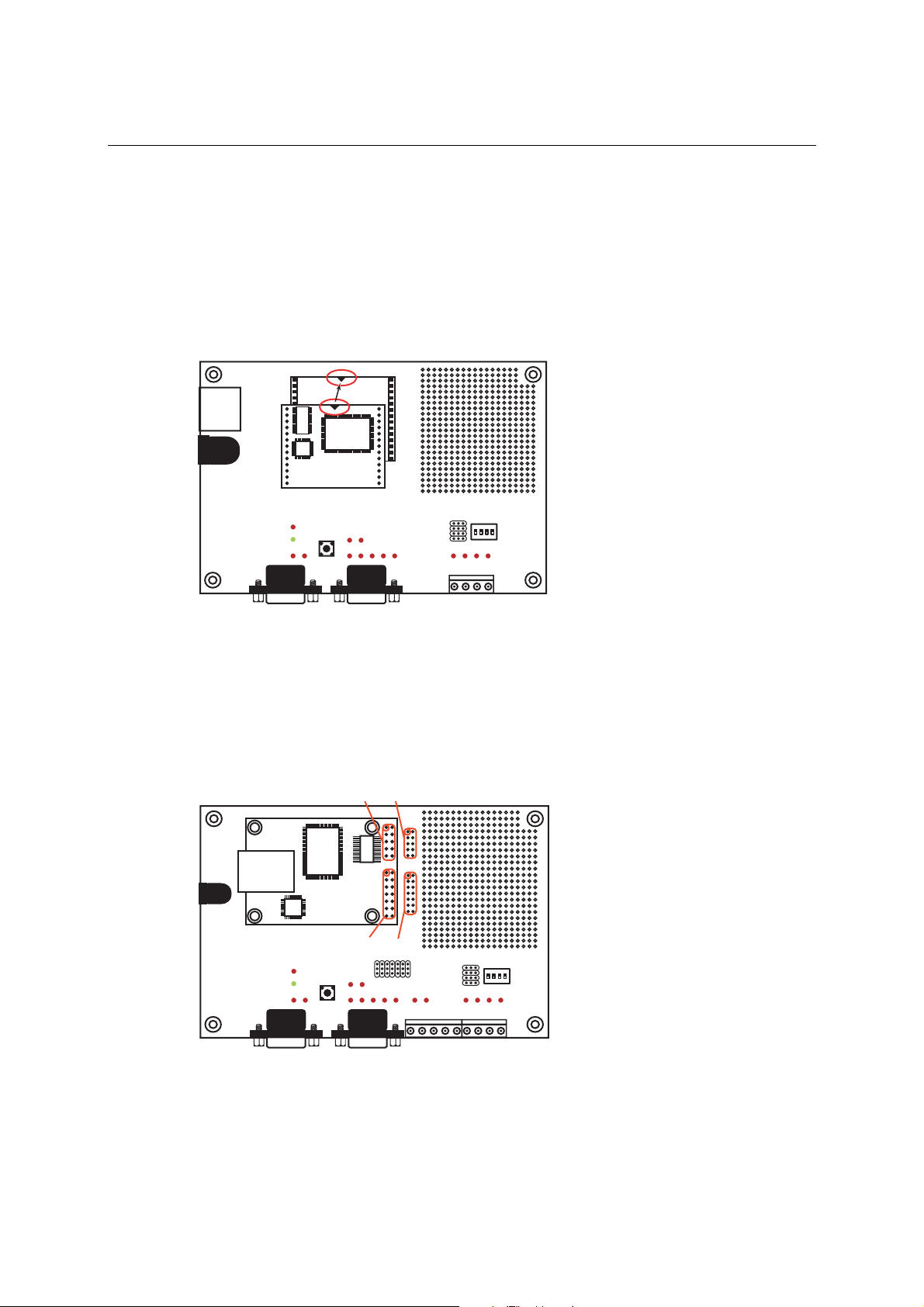
Installing the NE-4100T onto the NE-4100-ST
Before using the NE-4100-ST evaluation board with the module, disconnect the power supply,
network, and serial device. In the center of the evaluation board, there is a square with one white
inverted triangle (shown as black in the figure) on one of its sides, and 2 rows of female sockets on
the other two sides. The NE-4100T module also has a white inverted triangle on one of its sides.
When attaching the module to the evaluation board, make sure these 2 white inverted triangles are
facing the same direction, as shown in the following figure. After the module is installed, connect
the power supply, network, and serial device to the evaluation board.
NE-4100-ST Starter Kit
NE-4100T Series
Module
ON
DIP
1234
Installing the NE-4110S, NE-4110A onto the NE-4110-ST
The NE-4110S and NE -4110A modules are attached to the NE-4110-ST board using mounting
screws that are provided with the board. When attaching the module to the board, make sure that
the module is oriented so that the jumper banks on the module and the board are aligned as shown
below. Use the provided ribbon cables to connect jumper block J1 on the module to J9 on the
board, and jumper block J2 on the module to J10 on the board. When plugging in each ribbon
cable, make sure that the red key wire corresponds with pin 1 on each jumper block.
NE-4110-ST Starter Kit
NE-4110 Series
J1 J9
Module
J2
1
2
9
10
1
2
13
14
J10
12
910
12
13 14
ON
DIP
1234
3-3
Page 27
NE-4100 Series User’s Manual Getting Started
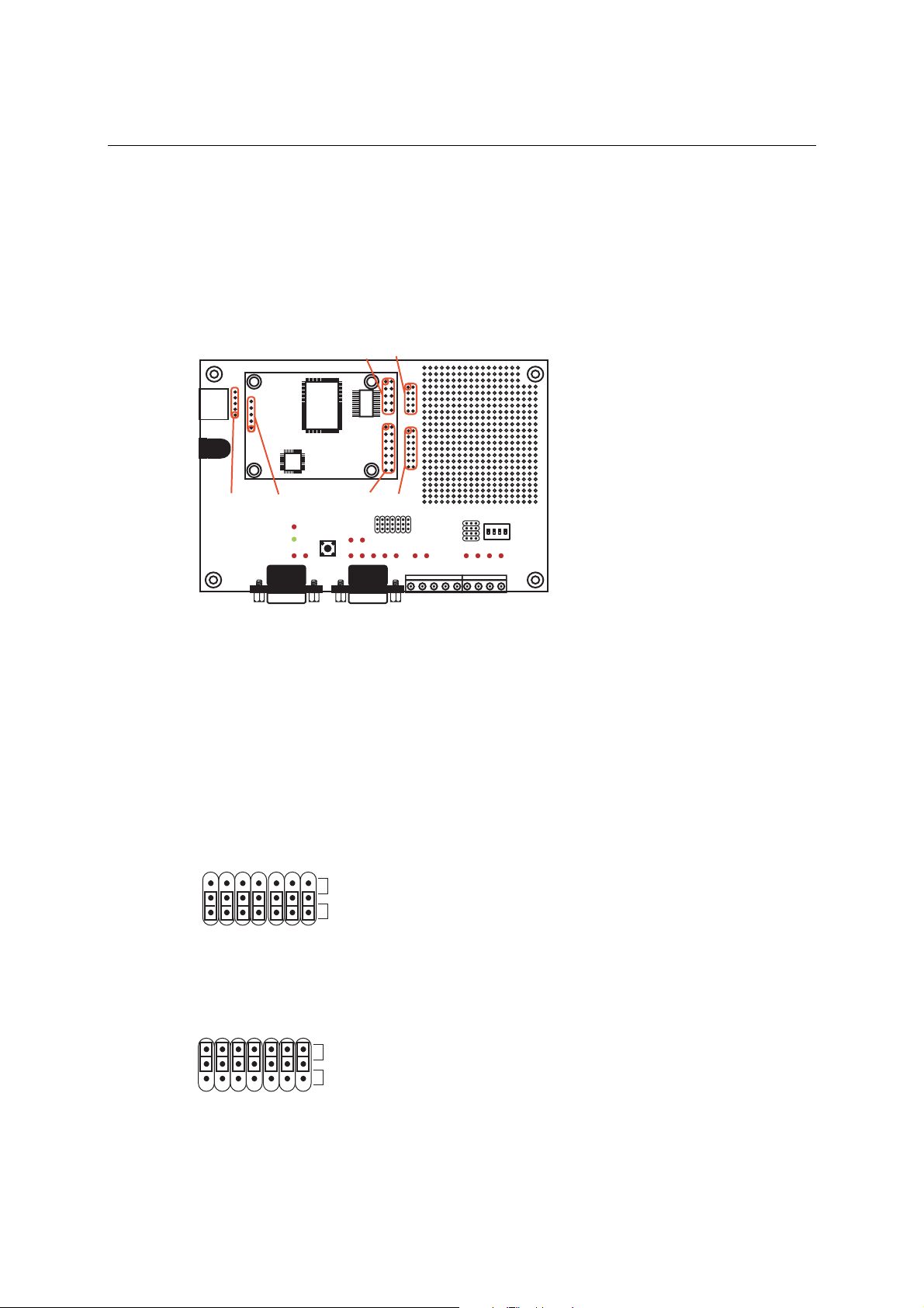
Installing the NE-4120S, NE-4120A onto the NE-4120-ST
The NE-4120S and NE -4120A modules are attached to the NE-4120-ST board using mounting
screws that are provided with the board. When attaching the module to the board, make sure that
the module is oriented so that the jumper banks on the module and the board are aligned as shown
below. Use the provided ribbon cables to connect jumper block J1 on the module to J9 on the
board, J2 on the module to J10 on the board, and J3 on the module to J7 on the board. When
plugging in each ribbon cable, make sure that the red key wire corresponds with pin 1 on each
jumper block.
NE-4120-ST Starter Kit
5
4
5
3
4
2
3
1
2
1
NE-4120 Series
J7
J3
J1 J9
Module
J2
1
2
9
10
1
2
13
14
J10
12
910
12
13 14
ON
DIP
1234
Selecting the Serial Interface
NE-4100 Series modules are available for different serial interfaces. The NE-4110S and NE-4120S
are designed for the RS-232 interface, and the NE-4110A and NE-4120A are designed for the
RS-422/485 interface. On the NE-4110-ST and NE-4120-ST evaluation boards, the Network
Enabler Interface jumper block is used to select the serial interface used for your particular
module.
For the NE-4110S and NE-4120S, the evaluation board should be configur ed for the RS-232
interface, as shown below.
JP2
Network Enabler
Interface
RS485
RS232
For the NE-4110A and NE-4120A, the evaluation board should be configured for the RS-485
interface, as shown below.
JP2
Network Enabler
Interface
RS485
RS232
3-4
Page 28
NE-4100 Series User’s Manual Getting Started
Note that the RS-485 interface is selected on the evaluation board for the NE-4110A and
NE-4120A modules, even when the module is operating in RS-422 mode. Please refer to
Panel Layout and Pin Assignments for additional details.
-
Chapter 2
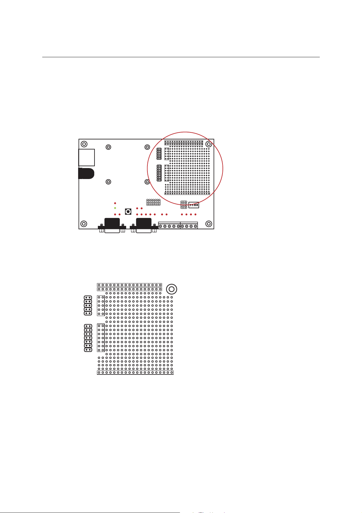
Circuit Pad for External Connection
A circuit pad is provided on the right side of each evaluation board for the development of
additional application circuits.
5V
3.3V
12
12
J3
J9
910
910
12
12
J4
J10
13 14
13 14
GND
ON
DIP
1234
The first row of the circuit pad is for connecting a 5V power supply; the second row is for
connecting a 3.3V power supply. The last row of the circuit pad is for grounding. Serial signals are
mapped to J3 as an extension of jumper block J9. DIO and LED signals are mapped to J4 as an
extension of jumper block J10. This means that pin assignments for J3 on the circuit pad are the
same as the pin assignments for jumper block J9; pin assignments for J4 on the circuit pad are the
same as the pin assignments for jumper block J10.
5V
3.3V
12
12
J3
J9
910
910
12
12
J4
J10
13 14
13 14
GND
Connecting the Power
Connect the 12 VDC power line with the evaluation board’s power jack. If the power is properly
supplied, the power LED will show a solid red color until the system is ready, at which time the
ready LED will show a solid green color.
3-5
Page 29
NE-4100 Series User’s Manual Getting Started
Connecting to the Network
To connect to the network for testing and development purposes, the module should be installed
onto its evaluation board. Make sure that the module is correctly installed onto the evaluation
board, then plug the Ethernet cable into the RJ45 jack. For models NE-4100T, NE-4120S, and
NE-4120A, the RJ45 jack is located on the evaluation board; for mode ls NE-4110S and NE-4110A,
the RJ45 jack is located on the module itself.
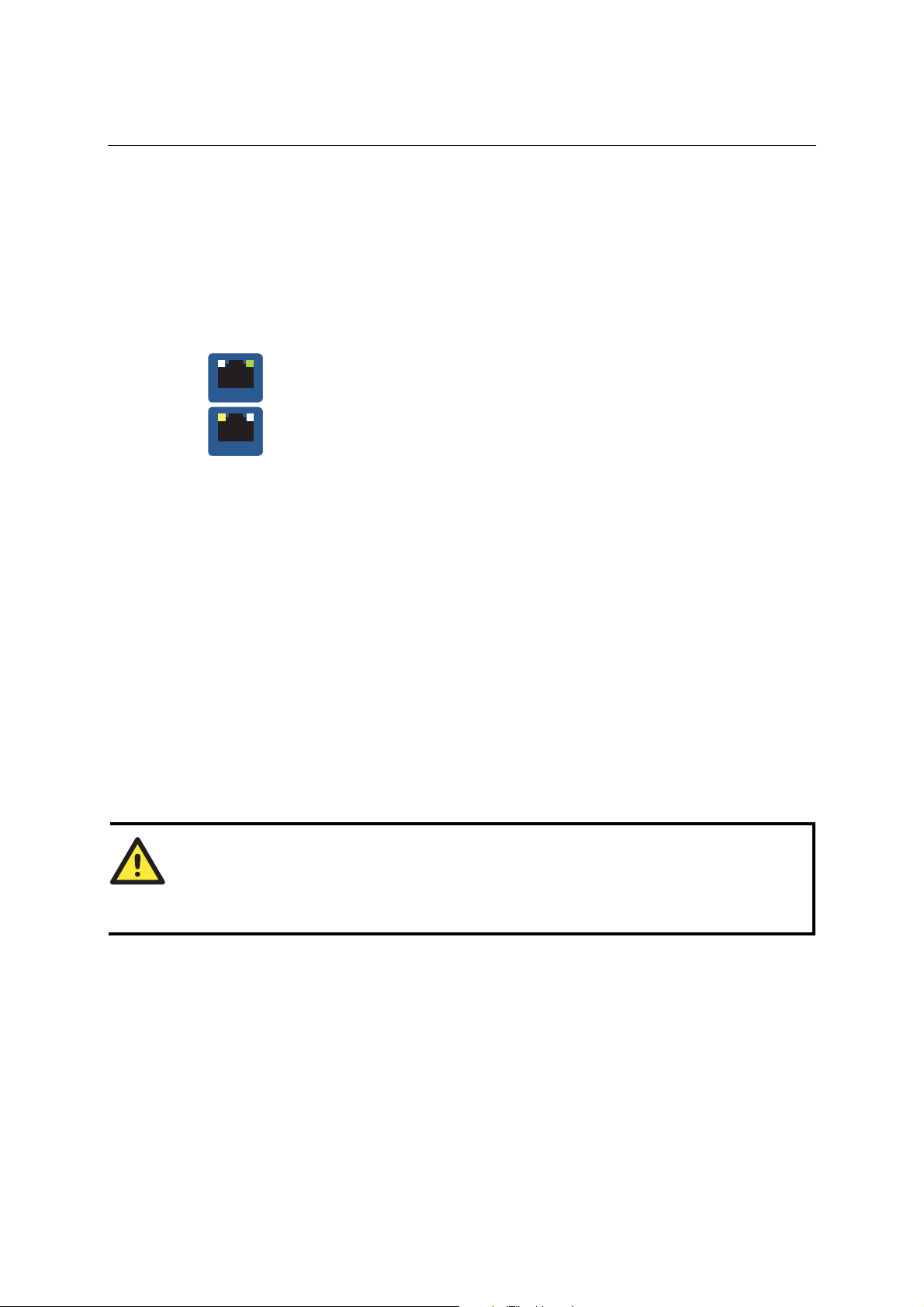
If the cable is properly connected, the RJ45 connector will indicate a valid connection to the
Ethernet as follows:
The green LED in the upper right corner blinks whe n t he cabl e is pr operly
LAN
LAN
When using a private IP address for the module, which is the factory default, make sure that
netmask and IP settings are configured appropriately in order to access the module from a host on
the network.
connected to a 100 Mbps Ethernet network, and data is being transmitted.
The yellow LED in the upper left corner blinks when the cable is properly
connected to a 10 Mbps Ethernet network, and data is being transmitted.
Connecting to a Serial Device
To connect to a serial device for testing and development purposes, the module should be installed
onto its evaluation board. The module’s serial signals are routed to and from the RS-232 COM port
on the evaluation board Use a serial data cable to connect the serial device to the COM port on the
evaluation board.
Digital I/O Channel Settings
Each module provides 4 digital I/O (DIO) channels. All 4 DIO channels may be configured by
software for either digital output or digital input mode. A DI channel is a channel that is operating
in digital input mode; a DO channel is a channel that is operating in digital output mode. You may
use the evaluation board’s Digital Output LEDs and Digital Input DIP switches as the digital input
and output devices, or you may connect digital input/output devices to the DI/O Terminal Block.
ATTENTION
When using a digital input device connected to the DI/O Terminal Block, the corresponding
Digital Input DIP switch must be set to “OFF” or “High”. Setting the DIP switch to “ON” or
“Low” will interfere with the signal from your digital input device.
3-6
Page 30
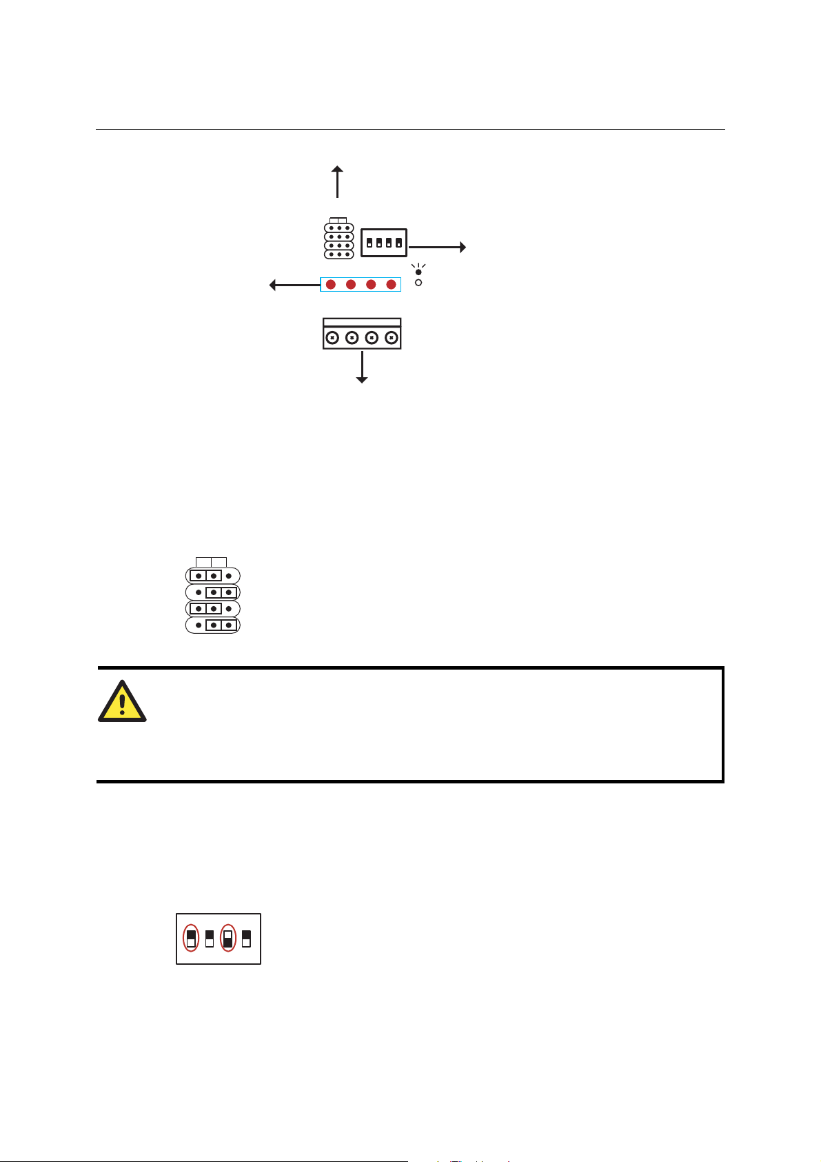
NE-4100 Series User’s Manual Getting Started
DI/O Selectable Jumper
DI/O Mode
DI DO
Digital Input
Digital Output LEDs
0
1
2
3
DO0 DO1 DO2 DO3
DO0 DO1 DO2 DO3
0123
ON
1234
Digital Output
DIP
ON: Low
OFF: High
: Low
: High
Digital Input Signal Setting Switch
DI/O Terminal Block
DI/O Mode jumpers 0 through 3 correspond with DIO channels 0 through 3. The jumper’s position
determines whether the corresponding channel is linked to a DIP switches or to an LED. When a
channel’s jumper is set to the DI position, the channel’s input signal is controlled by the
corresponding Digital Input DIP switch. When the jumper is set to the DO position, the channel’s
output signal is routed to the corresponding Digital Output LED. For example, if DIO channel 0 is
operating as a digital input channel, setting DI/O Mode jumper 0 to the DI position enables the use
of DIP switch 0 as that channels’ input device.
DI/O Mode
DI DO
0
1
2
3
ATTENTION
The DI/O Mode jumpers are used to tell the evaluation board whether to use the Digital Output
LEDs or the Digital Input DIP switches. The jumpers do not control the channel’s mode. Input
and output mode is configured through the web, serial, or Telnet console, or through Network
Enabler Administrator.
When using a Digital Input DIP switch as your input device, the “ON” position corresponds to
“Low” status and the “OFF” position corresponds to “High” status. The result can be monitored
with the Network Enabler Administrator or with the web console. Make sure all DIP switches are
set to “OFF” if you are using your own digital input device that is connected to the evaluation
board’s terminal block.
Digital Input
0123
ON
DIP
1234
ON: Low
OFF: High
3-7
Page 31
NE-4100 Series User’s Manual Getting Started
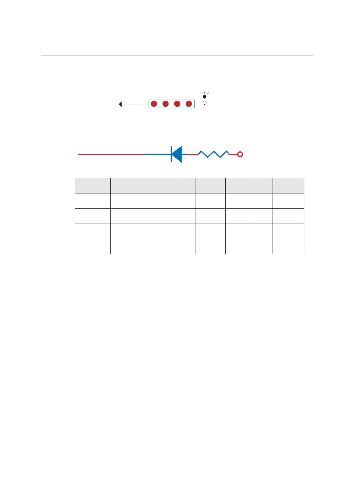
For channels in digital output mode, “Low” and “High” status is controlled from within the web
console. When using a Digital Output LED as your output device, “Low” status will be expressed
by the LED lighting up, and “High” status will be expressed by the LED turning off.
Digital Output
DO0 DO1 DO2 DO3
Digital Output LEDs
: Low
: High
Digital Output LED Circuit Design
The figure shown below is the digital output LED circuit design. This is known as the “sink”
design.
Dout
3.3V
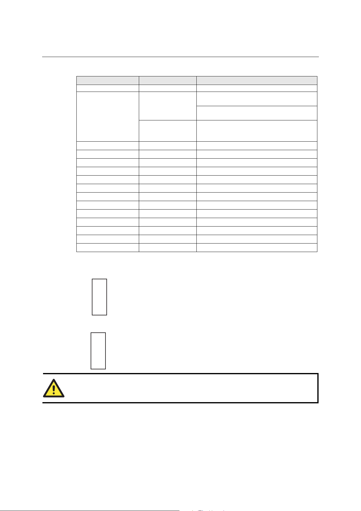
When developing your own applications, you need to be aware of the voltage limits shown below.
Min. Max. Unit Conditions
Low-level
Input Voltage
High-level
Input Voltage
Low-level
Input Voltage
High-level
Input Voltage
Maximum voltage when DI is set
to “Low” status.
Minimum voltage when DI is set
to “High” status. 0.7xVCC ----- V
Maximum voltage when DO is set
to “Low” status. ----- 0.4 V
Minimum voltage when DO is set
to “High” status
----- 0.3xVCC V
2.4 ----- V
The output current for digital output channels carries only 1 mA.
3-8
Page 32

4
4
Chapter 4. Choosing the Proper Operation Mode
In this section, we describe the various operation modes of NE-410 0 Seri es modules. Depending
on your intended use, the operation mode will determine how serial communication is handled by
the network. There is an operation mode for COM port mapping from the host computer as well
operation modes for TCP/IP protocols. After choosing the proper operating mode in this chapter,
please refer to subsequent chapters for details on configuration parameters.
The following topics are covered in this chapter:
Overview
TCP Server Mode
TCP Client Mode
UDP Mode
Real COM Mode
Page 33

NE-4100 Series User’s Manual Choosing the Proper Operation Mode
Overview
NE-4100 Series modules act as a bridge to connect your serial devices to the Ethernet. The built-in
TCP/IP stack means less time spent on programming networking protocols. With one step you may
choose the proper operation mode, then use your computer to access, manage, and configure your
serial device from anywhere in the world over the Internet.
Traditional SCADA and data collection systems rely on serial ports (RS-232/422/485) to collect
data from various kinds of instruments. Since NE-4100 Series modules convert between serial and
Ethernet signals, your SCADA and data collection system can be made accessible from every
device connected to a standard TCP/IP network, regardless of whether the devices are used locally
or at a remote site.
Three different socket modes—TCP Server, TCP Client, and UDP Server/Client—are available, as
well as a Real COM mode. The main difference between the TCP and UDP protocol is that TCP
guarantees delivery of data by requiring the recipient to send an acknowledgement to the sender.
UDP does not require this type of verification, making it possible to offer speedier delivery. UDP
also allows multicasting of data to groups of IP addresses.
ATTENTION
The figures in this chapter use the NE-4110S as an example, but they apply to all models in the
NE-4100 Series.
TCP Server Mode
In TCP Server mode, the module is assigned a unique IP
address and port number on the TCP/IP network. The
module waits passively to be contacted by the host
computer, allowing the host computer to establish a
connection with and obtain data from the serial device.
This operation mode also supports up to 4 simultaneous
connections, so that multiple hosts can collect data from
the same serial device—at the same time.
As illustrated in the figure, data transmission proceeds as
follows:
1. The host connects to the module configured for TCP
Server mode.
2. Once the connection is established, data can be
transmitted in both directions—from the host to the
module, and from the module to the host.
4-2
Page 34

NE-4100 Series User’s Manual Choosing the Proper Operation Mode
TCP Client Mode
In TCP Client mode, the module can actively
establish a TCP connection to a pre-defined host
computer when serial data arrives.
After the data has been transferred, the module can
automatically disconnect from the host computer by
using the “TCP alive check time” or “Inactivity
time” settings. Please refer to the following chapters
for more details.
As illustrated in the figure, data transmission
proceeds as follows:
1. The module actively establishes a connection
based on the conditions set in the firmware.
You may let the module connect to a remote
host on startup, or connect later when data
from serial device arrives.
2. Once the connection is established, data can be
transmitted in both directions—from the host
to the module, and from the module to the host.
UDP Mode
UDP mode is faster and more efficient than
TCP modes. In UDP mode, you can multicast
data from the serial device to multiple host
computers, and the serial device can also
receive data from multiple host computers,
making this mode ideal for message display
applications.
4-3
Page 35

NE-4100 Series User’s Manual Choosing the Proper Operation Mode
Real COM Mode
Real COM mode allows users to continue using
software that was written for pure serial
communications applications. Each module
comes equipped with COM drivers for
Windows systems (95 and above). The serial
module’s serial port is mapped by the driver to
an IP address and port number. The driver
intercepts data sent to the host’s COM port,
packs it into a TCP/IP packet, and then
redirects it through the host’s Ethernet card. At
the other end of the connection, the module
accepts the Ethernet frame, unpacks the TCP/IP
packet, and then transparently sends the data to
the attached serial device. The driver thus
establishes a transparent connection between
the host and serial device, allowing the host to
treat the networked device as if it were directly
attached.
ATTENTION
The Real COM driver comes with Network Enabler Administrator, which is part of the NE-4100
Series Administration Suite.
ATTENTION
Real COM mode can allow several hosts to have simultaneous access to the module. The driver
controls host access to attached serial devices by checking the host’s IP address against the
Accessible IP list.
Use the Accessible IP table to restrict access to the module when a public IP address is required
for your application.
4-4
Page 36

5
5
Chapter 5. Initial IP Address Configuration
When setting up your NE-4100 Series module for the first time, the first thing you should do is
configure the IP address. This chapter introduces the methods that can be used to configure the
module’s IP address. For more details about network settings, please refer to the
section from
This chapter includes the following sections:
Chapter 6 - Web Console Configuration.
Network Settings
Static vs. Dynamic IP Address
Factory Default IP Address
NE-4100 Series Administration Suite Å recommended configuration method
ARP
Telnet Console
Serial Console (19200, n, 8, 1)
Page 37

NE-4100 Series User’s Manual Initial IP Address Configuration
Static vs. Dynamic IP Address
Determine whether the module will use a Static IP or Dynamic IP (either DHCP or BOOTP
application).
z If the module is used in a Static IP environment, you will configure the IP address directly.
z If the module is used in a Dynamic IP environment, you will configure the module to obtain
an IP address dynamically with DHCP, DHCP/BOOTP, or BOOTP.
ATTENTION
Consult your network administrator on how to reserve a fixed IP address for the module in the
MAC-IP mapping table when using a DHCP Server or BOOTP Server. For most applications, you
should assign a fixed IP address to the module.
Factory Default IP Address
The module is configured with the following default private IP address:
192.168.127.254
Please note that IP addresses of the form 192.168.xxx.xxx are referred to as private IP addresses,
since it is not possible to directly access a device configured with a private IP address from a
public network. For example, you would not be able to ping such a device from an outside Internet
connection. Applications that require sending data over a public network, such as the Internet,
require setting up the server with a valid public IP address, which can be leased from a local ISP.
NE-4100 Series Administration Suite
The NE-4100 Series Administration Suite consists of some useful utilities that are used to
configure and manage the module. Please refer to
Series Administration Suite to set up the module’s IP addresses.
Chapter 7 for details on using the NE-4100
ARP
You can use the ARP (Address Resolution Protocol) command to set up the module’s IP address.
The ARP command tells your computer to associate the module’s MAC address with the intended
IP address. You must then use Telnet to access the module, at which point the module’s IP address
will be reconfigured.
ATTENTION
In order to use ARP, both your computer and the module must be connected to the same LAN.
You may also use a cross-over Ethernet cable to connect the module directly to your computer’s
Ethernet port.
Your module must be configured with the factory default IP address before executing the ARP
command.
5-2
Page 38

NE-4100 Series User’s Manual Initial IP Address Configuration
To configure the IP address using ARP, follow these instructions:
1. Obtain a valid IP address for the module from your network administrator.
2. Obtain the module’s MAC address from the label on the module.
3. Execute the ‘arp -s’ command from your computer’s MS-DOS prompt by typing:
arp –s <new IP address> 00-90-E8-xx-xx-xx
For example,
arp –s 192.168.200.100 00-90-E8-00-00-00
In the example above, 192.168.200.100 is the new IP address and 00-90-E8-00-00-00 is the
module’s MAC address, as obtained in steps 1 and 2.
4. Execute a special Telnet command by typing:
telnet <new IP address> 6000
For example.
telnet 192.168.200.100 6000
After issuing this command, a Connect failed message
will appear, as shown here. After the module reboots, its
IP address will be updated to the new address, and you can
reconnect using Telnet, web, or Network Enabler
Administrator to verify that the update was successful.
Telnet Console
Depending on how your computer and network are configured, you may find it convenient to use
network access to set up your module’s IP address. This can be done using the Telnet program,
which requires that the module have a network connection and an IP address.
1. From the Windows desktop, click on Start and then select Run.
2. Telnet to the module’s current IP address. If this
is the first time configuring the module, you
will telnet to the default IP address by typing
telnet 192.168.127.254
in the Open text box, then clicking OK.
5-3
Page 39

NE-4100 Series User’s Manual Initial IP Address Configuration
3. Select Network settings by pressing 2 and then Enter.
4. Select IP address by pressing 1 and then Enter.
5. Use the Backspace key to er ase the current IP address,
then type in the new IP address and press Enter.
5-4
Page 40

NE-4100 Series User’s Manual Initial IP Address Configuration
6. Press any key to continue.
7. Press M and then Enter to return to the main menu.
8. Press S and then Enter to Save/Restart the system.
9. Press Y and then Enter to save the new IP address and
restart the module.
Serial Console (19200, n, 8, 1)
If you wish to configure the IP address of the module without going through the network, you may
use the serial console, which involves connecting a serial terminal directly to the RS-232 console
port on the evaluation board. Moxa offers a free utility called PComm Terminal Emulator that can
5-5
Page 41

NE-4100 Series User’s Manual Initial IP Address Configuration
be used for this purpose, although you are free to choose among other terminal emulators that are
widely available. PComm Lite may be downloaded at www.moxa.com.
The following instructions show the procedure using PComm Lite. If you are using another utility,
the instructions may vary slightly.
1. Plug one end of a serial cable into the RS-232 DEBUG (P1) serial port on the evaluation
board; plug the other end directly into your computer’s male RS-232 serial port.
2. From the Windows desktop, click on Start Æ Programs Æ PComm Lite Æ Terminal
Emulator.
3. When the PComm T erminal Emulator window
opens, select Open from the Port Manager
menu, or simply click on the Open icon.
4. The Property window opens automatically. On
the Communication Parameter tab, select the
appropriate COM port for the connection, COM1
in this example. The parameters should be set to
19200 for Baud Rate, 8 for Data Bits, None for
Parity, and 1 for Stop Bits.
5. On the Terminal tab, select ANSI or VT100 for
Terminal Type and then click OK.
If you select Dumb Terminal as the terminal
type, some of the console functions—especially
the Monitor function—may not work properly.
6. Enter any character to switch automatically from data mode to console mode.
7. The serial console will open up. At this point, it
will look exactly the same as the Telnet console.
Please continue to step 3 in the previous Telnet
Console section for the rest of the instructions on
setting up the IP address.
5-6
Page 42

6
6
Chapter 6. Web Console Configuration
The web console is the most user-friendly way to configure your NE-4100 Series module. This
chapter introduces the web console function groups and function definitions.
This chapter includes the following sections:
Opening Y our Browser
Web Console Navigation
Basic Settings
Network Settings
Serial Settings
Operating Settings
¾ TCP Server Mode
¾ Real COM Mode
¾ TCP Client Mode
¾ UDP Mode
Accessible IP Settings
Auto Warning Settings
¾ E-mail and SNMP Trap
¾ Event Type
Digital IO
¾ DIO Settings
¾ DIO Monitor
Serial Command Mode
Change Password
Load Factory Defaults
Save/Restart
Page 43

NE-4100 Series User’s Manual Web Console Configuration
Opening Your Browser
1. Open your browser with the cookie function enabled. (To enable your browser for cookies,
right click on your desktop Internet Expl o rer i c on, select Properties, click on the Security tab,
and then select the three Enable options as shown in the figure below.)
2. Type 192.168.127.254 in the Address box (use the correct IP addres s if different from the
default), and then press Enter.
ATTENTION
If you use other web browsers, remember to enable the functions to “allow cookies that are stored
on your computer” or “allow per-session cookies.”
NE-4100 Series modules only use cookies for password transmission.
ATTENTION
Please refer to
The examples in this chapter use the factory default IP address (192.168.127.254).
Chapter 5 - Initial IP Address Configuration for instructions on IP configuration.
6-2
Page 44

NE-4100 Series User’s Manual Web Console Configuration
3. The web console will open. On this page, you can see a brief description of the web console’s
eleven function groups.
Note: “Serial Command Mode” is supported in firmware version 3.0 and above.
ATTENTION
If you can’t remember the password, the ONLY way to configure the module is to load factory
defaults by using the reset button located near the DB9 male serial port on the evaluation board.
Remember to use Network Enabler Administrator to export the configuration file when you have
finished the configuration. After using the reset button to load factory defaults, your configuration
can be easily reloaded into the module. Please refer to
and importing configuration settings.
Chapter 7 for more details about exporting
Web Console Navigation
On the web console, the left panel is the navigation panel and contains an expandable menu tree
for navigating among the various settings and categories. When you click on a menu item in the
navigation panel, the main window will display the corresponding options for that item.
Configuration changes can then be made in the main window. For example, if you click on Basic
Settings in the navigation panel, the main window will show a page of basic settings that you can
configure.
You must click on the Submit button to keep your configuration changes. The Submit button will
be located at the bottom of every page that has configurable settings. If you navigate to another
page without clicking the Submit button, your settings will not be retained.
Changes will not take effect until they are saved and the module is restarted! You may
complete this in one step by clicking on Save/Restart after you submit a change. If you restart the
module without saving your configuration, the module will discard all submitted changes.
6-3
Page 45

NE-4100 Series User’s Manual Web Console Configuration
Basic Settings
Note: “Serial Command Mode” is supported in firmware version 3.0 and above.
Server name
Setting Factory Default Necessity
1 to 39 characters NP[model name]_[Serial No.] Optional
This option can be used to specify the location or application of the module, which may be useful
when managing more than one module on the network.
Time
The module has a built-in Real-Time Clock for time calibration functions. Functions such as Auto
warning e-mail or SNMP trap can add real-time information to the message.
ATTENTION
Always select and submit the time zone before modifying the time. The console will display the
real time according to the time zone compared to GMT.
If you would like to modify the real time clock, select Local T i me. The module’s firmware will
modify the GMT time according to the Time Zone.
Time zone
Setting Factory Default Necessity
User selectable time zone GMT (Greenwich Mean Time) Optional
Local time
Setting Factory Default Necessity
User adjustable time. GMT (Greenwich Mean Time) Optional
Click on the Modify button to open the Modify time
settings window to input the correct local time.
6-4
Page 46

NE-4100 Series User’s Manual Web Console Configuration
Time server
Setting Factory Default Necessity
IP or domain address
(E.g., 192.168.1.1, time.stdtime.g ov.tw, or
time.nist.gov)
NE-4100 Series modules use SNTP (RFC-1769) for auto time calibration.
Enter the Time Server IP address or domain address. When the Time Server IP address is provided,
the module will request time information from the Time Server every 10 minutes.
None Optional
Console
Web console, Telnet console
Setting Factory Default Necessity
Enable or Disable Enable Required
The web console and Telnet console can be disabled for security reasons. In some cases, you may
want to disable one or both of these console utilities as an extra precaution to prevent unauthorized
users from accessing the module. The factory default for both web console and Telnet console is
Enable.
ATTENTION
If you disable both the web console and Telnet console, you can still use the serial console or
Network Enabler Administrator to configure the module.
Network Settings
Note: “Serial Command Mode” is supported in firmware version 3.0 and above.
You must assign a valid IP address to the module before it will work in your network environment.
Your networ k system administrator should provide you with an IP address and related settings for
your network. The IP address must be unique within the network; otherwise the module will not
have a valid connection to the network. First time users can refer to
Configuration for more information.
Chapter 5 - Initial IP Address
6-5
Page 47

NE-4100 Series User’s Manual Web Console Configuration
IP configuration
Method Function Definition
Static User defined IP address, Netmask, Gateway.
DHCP DHCP Server assigned IP address, Netmask, Gateway, DNS, and Time Server
DHCP Server assigned IP address, Netmask, Gateway, DNS, and Time
DHCP/BOOTP
BOOTP BOOTP Server assigned IP address
IP configuration is a required field. The default setting is Static.
ATTENTION
In Dynamic IP environments, the module will attempt to obtain an IP address from the DHCP or
BOOTP server 3 times at 30-second intervals. The timeout for the first try will be 1 second, the
second try will be to 3 seconds, and the last try will be 5 seconds.
If the DHCP/BOOTP Server is unavailable, the module will use the default IP address
(192.168.127.254), netmask, and gateway settings.
Server, or BOOTP Server assigned IP address
IP Address
Setting Factory Default Necessity
E.g., 192.168.1.1
(IP addresses of the form x.x.x.0 and
x.x.x.255 are invalid.)
An IP address is a number assigned to a network device, such as a computer, as a permanent
address on the network. Computers use the IP address to identify and talk to each other over the
network. Choose a proper IP address which is unique and valid in your network environment.
192.168.127.254 Required
Netmask
Setting Factory Default Necessity
E.g., 255.255.255.0 255.255.255.0 Required
A subnet mask represents all the network hosts at one geographic location, in one building, or on
the same local area network. When a packet is sent out over the network, the module will use the
subnet mask to check whether the host specified in the packet is on a local network segment. If the
address is on the same network segment as the module, a connection is established directly from
the module. Otherwise, the connection is established through the default gateway.
Gateway
Setting Factory Default Necessity
E.g., 192.168.1.1 None Optional
A gateway acts as an entrance to another network. Usually, the computers that control traffic
within the network or at the local Internet service provider are gateway no des. The module needs
to know the IP address of the default gateway computer in order to communicate with the hosts
outside the local network environment. For correct gateway IP address information, consult your
network administrator.
6-6
Page 48

NE-4100 Series User’s Manual Web Console Configuration
DNS server 1 / DNS sever 2
Setting Factory Default Necessity
E.g., 192.168.1.1
(IP addresses of the form x.x.x.0 and
x.x.x.255 are invalid.)
Domain Name System (DNS) is how Internet domain names are identified and translated into IP
addresses. A domain name is an alphanumeric name, such as moxa.com, that it is usually easier to
remember. A DNS server is a host that translates the text-based domain name into the
corresponding numeric IP address which is used to establish a TCP/IP connection. When the user
enters a website address, the computer asks a DNS server for the website’s IP address to connect to
the web server.
When a DNS server is specified, the module acts as DNS client and will allow domain names
instead of IP addresses to be used on the we b c ons ol e. The following web console fields support
the use of domain names: Time Sever IP Address, TCP Client-Destination IP Address, Mail Server,
SNMP Trap IP Address, and IP Location Server. Two DNS servers may be specified, DNS server
1 and DNS server 2. DNS server 2 is included for use when DNS sever 1 is unavailable.
None Optional
SNMP Settings
Community name
Setting Factory Default Necessity
1 to 39 characters
(E.g., Support, 886-89191230 #300)
A community name is a plain-text password mechanism that is used to weakly authenticate queries
to agents of managed network devices.
public Optional
Contact
Setting Factory Default Necessity
1 to 39 characters
(E.g., Support, 886-89191230 #300)
The SNMP contact information usually includes an emergency contact name and telephone or
pager number.
None Optional
Location
Setting Factory Default Necessity
1 to 39 characters
(E.g., Floor 1, office 2)
Enter a location string for SNMP agents. This string is usually set to the street address where the
module is physically located.
None Optional
IP Address report
When the module is used in a dynamic IP environment, additional time must be spent on IP
management tasks. For example, when a module is operating as a server (TCP or UDP modes), a
PC operating as a client will need to know the module’s IP address. If the DHCP server assigns a
new IP address to the module, the PC must have some way of obtaining the module’s new IP
address. The IP Address report fields are used to set up periodic reporting of the module’s IP
address when the module’s IP address is assigned by a server. The IP address report is sent
automatically at regular intervals to an IP address and TCP port number of your choice. There are
two ways view the module’s IP address report on a PC:
6-7
Page 49

NE-4100 Series User’s Manual Web Console Configuration
z Install Network Enabler Administrator and use the built-in IP Address Report function.
z Develop software that parses the IP address report data. Please refer t o Appendix C for details
on how to parse the module’s IP address report data.
Auto report to IP
Setting Factory Default Necessity
E.g., 192.168.1.1 or URL
(IP addresses of the form x.x.x.0 and
x.x.x.255 are invalid.)
If left blank, auto IP reporting is disabled. If an IP address is entered along with a TCP port
number, the IP address reports will be sent to the specified address and port number.
None Optional
Auto report to TCP port
Setting Factory Default Necessity
E.g., 4001 4002 Optional
If left blank, auto IP reporting is disabled. If a TCP port number is entered along with an IP
address, the IP address reports will be sent to the specified address and port number.
Auto report period
Setting Factory Default Necessity
Time interval (in seconds) 10 Optional
The Auto report period field specifies how often the module will report its IP address. An auto
report period of 10 seconds means that an IP address report will be sent every 10 seconds.
ATTENTION
The module will send IP address reports only when assigned an IP address from a DHCP or
BOOTP server. If a connection to a DHCP or BOOTP server is not available, no IP address report
will be sent..
Serial Settings
Note: “Serial Command Mode” is supported in firmware version 3.0 and above.
6-8
Page 50

NE-4100 Series User’s Manual Web Console Configuration
Port Alias
Setting Factory Default Necessity
1 to 15 characters
(E.g., PLC-No.1)
This function is designed for future use. You may enter a string to help in the module’s serial port
from other serial ports.
None Optional
Serial Parameters
ATTENTION
Refer to the serial communication parameters in your serial device’s user’s manual. The module’s
serial parameters should be the same as the parameters used by your serial device.
Baud Rate
Setting Factory Default Necessity
50 bps to 115.2 Kbps for PCB V1.x
110 bps to 230.4 Kbps for PCB V2.x
The module can be set for baud rates between 50 bps and 115.2 Kbps for PCB V1.x and between
110 bps to 230.4 Kbps f or PCB V2.x.
115.2 Kbps Required
Data Bits
Setting Factory Default Necessity
5, 6, 7, 8 8 Required
When the user sets Data Bits to 5 bits, the Stop Bits setting will automatically change to 1.5 bits.
Stop Bits
Setting Factory Default Necessity
1, 2 1 Required
Stop Bits will be set to 1.5 when Data Bits is set to 5 bits.
Parity
Setting Factory Default Necessity
None, Even, Odd, Space, Mark None Required
Flow control
Setting Factory Default Necessity
None, RT S/CT S, DTR/DSR, XON/XOFF RTS/CTS Required
FIFO
Setting Factory Default Necessity
Enable, Disable Enable Required
Each module’s serial port provides a 16-byte FIFO both in the Tx and Rx directions. Disable the
FIFO setting when your serial device does not have a FIFO to prevent data loss during
communication.
6-9
Page 51

NE-4100 Series User’s Manual Web Console Configuration
Operating Settings
TCP Server Mode
Note: “Serial Command Mode” is supported in firmware version 3.0 and above.
TCP alive check time
Setting Factory Default Necessity
0 to 99 min 7 min Optional
0 min: The TCP connection is not closed due to an idle TCP connection.
1 to 99 min: The module automatically closes the TCP connection if there is no TCP activity for
the given time. After the connection is closed, the module starts listening for another host’s TCP
connection.
Inactivity time
Setting Factory Default Necessity
0 to 65535 ms 0 ms Optional
0 ms: The TCP connection is not closed due to an idle serial line.
0-65535 ms: The module automatically closes the TCP connection if there is no serial data activity
for the given time. After the connection is closed, the module starts listening for another host’s
TCP connection.
This parameter defines the maintenance status as Closed or Listen on the TCP connection. The
connection is closed if there is no incoming or outgoing data through the serial port during the
specific Inactivity time.
If Inactivity time is set to 0, the current TCP connection is maintained until there is a connection
close request. Even with Inactivity time is disabled, the module will still check the connection
status between itself and the remote host by sending “keep alive” packets periodically. If the
remote host does not respond to the packet, it assumes that the connection was closed down
unintentionally. The module will then force the existing TCP connection to close.
ATTENTION
The Inactivity time should be longer than the Force transmit timeout. To prevent the unintended
loss of data due a session getting disconnected, it is strongly recommended that this value is set
large enough so that the intended data transfer is completed.
6-10
Page 52

NE-4100 Series User’s Manual Web Console Configuration
Max connection
Setting Factory Default Necessity
1, 2, 3, 4 1 Required
Max connection is used when the user needs to receive data from different hosts simultaneously.
The factory default only allows 1 connection at a time.
Max. connection 1: The module will only allow 1 host to open the TCP connection to the specific
serial port.
Max connection 2 to 4: The module will allow requests from between 2 and 4 host’s TCP
connection to open the serial port at the same time. When multiple hosts establish a TCP
connection to the serial port at the same time, the module will duplicate the serial data and transmit
to all of the hosts. Ethernet data is sent on a first-in-first-out basis to the serial port when data
comes into the module from the Ethernet interface.
Delimiter 1
Setting Factory Default Necessity
00 to FF “0” for None Optional
Delimiter 2
Setting Factory Default Necessity
00 to FF “0” for None Optional
The Delimiter fields are used to specify a character or 2-character sequence which will act as a
marker to control packing of serial data. By default, no delimiter characters are defined, so the
module transmits data as soon as it is received. When a delimiter character or characters are
defined, the module will hold data in its buffer until it receives the delimiter character or
2-character sequence. When the delimiter is received, the module will pack up the data in its buffer
and send it through the Ethernet port.
Use Delimiter 1 to define the first delimiter character in hex. If only one delimiter character will be
used, Delimiter 2 should be set to “0”. If the delimiter will be a two-character sequence, use
Delimiter 2 to define the second character. To disable the use of delimiters, set both Delimiter 1
and Delimiter 2 to “0”.
Note that data packing is not only controlled by the delimiter; it is also influenced by the module’s
buffer size and the Force transmit field. If the delimiter has not been received by the time the 1K
buffer is full, the module will pack the data for network transmission and clear the buffer. Also, if
the module will also pack data for network transmission if the next byte of data is not received
within the Force transmit time.
ATTENTION
Do not enable Delimiter 2 if Delimiter 1 has been disabled. The delimiter function will not work
properly if Delimiter 2 is enabled without Delimiter 1.
Force transmit
Setting Factory Default Necessity
0 to 65535 ms 0 ms Optional
0: The force transmit timeout is disabled.
1 to 65535: If the module does not receive the next byte of data within the time specified, it will
packed the data in its buffer into the same data frame for network transmission.
6-11
Page 53

NE-4100 Series User’s Manual Web Console Configuration
The Force transmit field is typically used in conjunction with the Delimiter fields to specify how
data in the module’s buffer is packed for network transmission. When delimiters are used, the
module accumulates data in its buffer as it waits to receive a delimiter. If there is a break in
communication, data will be held in the buffer as the module continues to wait for a delimiter. The
Force transmit field allows you to specify the maximum amount of time that the module will wait
for data. With Force transmit enabled, the module will automatically pack the data in the buffer for
network transmission if no data is received for the specified time.
When set to 0, Force transmit is disabled, which means there is no time limit for how long the
module will wait to receive data. When set between 1 and 65535, the module will pack data as
soon as there has been no serial communication for the specified time.
The optimal force transmit time depends on your application, but it should be larger than one
character interval within the specified baud rate to have any effect. For example, assume that the
serial port is set to 1200 bps, 8 data bits, 1 stop bit, and no parity. In this case, the total number of
bits needed to send one character is 10 bits, and the time required to transfer one character is
(10 bits / 1200 bits/s) × 1000 ms/s = 8.3 ms.
Since it requires about 9 ms to send one character, the Force transmit should be 10 ms or more to
have any effect. At 9 ms or less, the module will simply pack every character as it is received,
which would be the same as if no delimiter characters or Force transmit time were specified at all.
Local TCP port
Setting Factory Default Necessity
1 to 65535 4001 Required
Use this field to indicate the TCP port that the module will use to listen to connections, and that
other devices must use to contact the module. To avoid conflicts with well known TCP ports, the
default is set to 4001.
Real COM Mode
Note: “Serial Command Mode” is supported in firmware version 3.0 and above.
TCP alive check time
Setting Factory Default Necessity
0 to 99 min 7 min Optional
0 min: The TCP connection is not closed due to an idle TCP connection.
1 to 99 min: The module automatically closes the TCP connection if there is no TCP activity for
the given time. After the connection is closed, the module starts listening for another host’s TCP
connection.
6-12
Page 54

NE-4100 Series User’s Manual Web Console Configuration
Max connection
Setting Factory Default Necessity
1, 2, 3, 4 1 Re qui red
Max connection is used when the user needs to receive data from different hosts simultaneously.
The factory default only allows 1 connection at a time. When Max Connection is set to 1, the Real
COM driver on the specific host has full control.
Max. connection 1: The module will only allow 1 host’s Real COM driver to open a connection to
the module’s serial port.
Max connection 2 to 4: The module will allow requests from between 2 and 4 different hosts to
open the module’s serial port at the same time. When multiple hosts’ Real COM drivers open the
serial port at the same time, the COM driver only provides a pure data tunnel without control
ability.
Application software that is based on the COM driver will receive a driver response of “success”
when the software uses any of the Win32 API functio ns. The firmware will only send the data back
to the driver on the host.
Data will be sent first-in-first-out when data comes into the module from the Ethernet interface.
ATTENTION
When Max connection is greater than 1, it means that the module will be used for
multi-connection applications. In multi-connection applications, when one host closes the COM
port, the module will suspend serial communication with all other hosts until that host
successfully closes the COM port.
In multi-connection applications, the module will use the serial communication parameters set in
the console. If the host opens the COM with parameters different from the module’s console
setting, data communication may not work properly.
Delimiter 1
Setting Factory Default Necessity
00 to FF “0” for None Optional
Delimiter 2
Setting Factory Default Necessity
00 to FF “0” for None Optional
The Delimiter fields are used to specify a character or 2-character sequence which will act as a
marker to control packing of serial data. By default, no delimiter characters are defined, so the
module transmits data as soon as it is received. When a delimiter character or characters are
defined, the module will hold data in its buffer until it receives the delimiter character or
2-character sequence. When the delimiter is received, the module will pack up the data in its buffer
and send it through the Ethernet port.
Use Delimiter 1 to define the first delimiter character in hex. If only one delimiter character will be
used, Delimiter 2 should be set to “0”. If the delimiter will be a two-character sequence, use
Delimiter 2 to define the second character. To disable the use of delimiters, set both Delimiter 1
and Delimiter 2 to “0”.
Note that data packing is not only controlled by the delimiter; it is also influenced by the module’s
buffer size and the Force transmit field. If the delimiter has not been received by the time the 1K
buffer is full, the module will pack the data for network transmission and clear the buffer. Also, if
6-13
Page 55

NE-4100 Series User’s Manual Web Console Configuration
the module will also pack data for network transmission if the next byte of data is not received
within the Force transmit time.
ATTENTION
Do not enable Delimiter 2 if Delimiter 1 has been disabled. The delimiter function will not work
properly if Delimiter 2 is enabled without Delimiter 1.
Force transmit
Setting Factory Default Necessity
0 to 65535 ms 0 ms Optional
0: The force transmit timeout is disabled.
1 to 65535: If the module does not receive the next byte of data within the time specified, it will
packed the data in its buffer into the same data frame for network transmission.
The Force transmit field is typically used in conjunction with the Delimiter fields to specify how
data in the module’s buffer is packed for network transmission. When delimiters are used, the
module accumulates data in its buffer as it waits to receive a delimiter. If there is a break in
communication, data will be held in the buffer as the module continues to wait for a delimiter. The
Force transmit field allows you to specify the maximum amount of time that the module will wait
for data. With Force transmit enabled, the module will automatically pack the data in the buffer for
network transmission if no data is received for the specified time.
When set to 0, Force transmit is disabled, which means there is no time limit for how long the
module will wait to receive data. When set between 1 and 65535, the module will pack data as
soon as there has been no serial communication for the specified time.
The optimal force transmit time depends on your application, but it should be larger than one
character interval within the specified baud rate to have any effect. For example, assume that the
serial port is set to 1200 bps, 8 data bits, 1 stop bit, and no parity. In this case, the total number of
bits needed to send one character is 10 bits, and the time required to transfer one character is
(10 bits / 1200 bits/s) × 1000 ms/s = 8.3 ms.
Since it requires about 9 ms to send one character, the Force transmit should be 10 ms or more to
have any effect. At 9 ms or less, the module will simply pack every character as it is received,
which would be the same as if no delimiter characters or Force transmit time were specified at all.
6-14
Page 56

NE-4100 Series User’s Manual Web Console Configuration
TCP Client Mode
Note: “Serial Command Mode” is supported in firmware version 3.0 and above.
TCP alive check time
Setting Factory Default Necessity
0 to 99 min 7 min Optional
0 min: The TCP connection is not closed due to an idle TCP connection.
1 to 99 min: The module automatically closes the TCP connection if there is no TCP activity for
the given time. After the connection is closed, the module starts listening for another host’s TCP
connection.
Inactivity time
Setting Factory Default Necessity
0 to 65535 ms 0 ms Optional
0 ms: The TCP connection is not closed due to an idle serial line.
0-65535 ms: The module automatically closes the TCP connection if there is no serial data activity
for the given time. After the connection is closed, the module starts listening for another host’s
TCP connection.
This parameter defines the maintenance status as Closed or Listen on the TCP connection. The
connection is closed if there is no incoming or outgoing data through the serial port during the
specific Inactivity time.
If Inactivity time is set to 0, the current TCP connection is maintained until there is a connection
close request. Even with Inactivity time is disabled, the module will still check the connection
status between itself and the remote host by sending “keep alive” packets periodically. If the
remote host does not respond to the packet, it assumes that the connection was closed down
unintentionally. The module will then force the existing TCP connection to close.
6-15
Page 57

NE-4100 Series User’s Manual Web Console Configuration
ATTENTION
The Inactivity time should be longer than the Force transmit timeout. To prevent the unintended
loss of data due a session getting disconnected, it is strongly recommended that this value is set
large enough so that the intended data transfer is completed.
ATTENTION
Inactivity time is only active when TCP connect on is set to Any Character.
Delimiter 1
Setting Factory Default Necessity
00 to FF “0” for None Optional
Delimiter 2
Setting Factory Default Necessity
00 to FF “0” for None Optional
The Delimiter fields are used to specify a character or 2-character sequence which will act as a
marker to control packing of serial data. By default, no delimiter characters are defined, so the
module transmits data as soon as it is received. When a delimiter character or characters are
defined, the module will hold data in its buffer until it receives the delimiter character or
2-character sequence. When the delimiter is received, the module will pack up the data in its buffer
and send it through the Ethernet port.
Use Delimiter 1 to define the first delimiter character in hex. If only one delimiter character will be
used, Delimiter 2 should be set to “0”. If the delimiter will be a two-character sequence, use
Delimiter 2 to define the second character. To disable the use of delimiters, set both Delimiter 1
and Delimiter 2 to “0”.
Note that data packing is not only controlled by the delimiter; it is also influenced by the module’s
buffer size and the Force transmit field. If the delimiter has not been received by the time the 1K
buffer is full, the module will pack the data for network transmission and clear the buffer. Also, if
the module will also pack data for network transmission if the next byte of data is not received
within the Force transmit time.
ATTENTION
Do not enable Delimiter 2 if Delimiter 1 has been disabled. The delimiter function will not work
properly if Delimiter 2 is enabled without Delimiter 1.
Force transmit
Setting Factory Default Necessity
0 to 65535 ms 0 ms Optional
0: The force transmit timeout is disabled.
1 to 65535: If the module does not receive the next byte of data within the time specified, it will
packed the data in its buffer into the same data frame for network transmission.
The Force transmit field is typically used in conjunction with the Delimiter fields to specify how
data in the module’s buffer is packed for network transmission. When delimiters are used, the
6-16
Page 58

NE-4100 Series User’s Manual Web Console Configuration
module accumulates data in its buffer as it waits to receive a delimiter. If there is a break in
communication, data will be held in the buffer as the module continues to wait for a delimiter. The
Force transmit field allows you to specify the maximum amount of time that the module will wait
for data. With Force transmit enabled, the module will automatically pack the data in the buffer for
network transmission if no data is received for the specified time.
When set to 0, Force transmit is disabled, which means there is no time limit for how long the
module will wait to receive data. When set between 1 and 65535, the module will pack data as
soon as there has been no serial communication for the specified time.
The optimal force transmit time depends on your application, but it should be larger than one
character interval within the specified baud rate to have any effect. For example, assume that the
serial port is set to 1200 bps, 8 data bits, 1 stop bit, and no parity. In this case, the total number of
bits needed to send one character is 10 bits, and the time required to transfer one character is
(10 bits / 1200 bits/s) × 1000 ms/s = 8.3 ms.
Since it requires about 9 ms to send one character, the Force transmit should be 10 ms or more to
have any effect. At 9 ms or less, the module will simply pack every character as it is received,
which would be the same as if no delimiter characters or Force transmit time were specified at all.
Destination IP address 1/2/3/4
Setting Factory Default Necessity
IP address or doma in name
(e.g., 192.168.1.1)
Use this field to specify the remote hosts that the module will connect to.
None Required
ATTENTION
Up to 4 connections can be established between the module and hosts. The connection speed or
throughput may be low if one of the four connections is slow. In this case, the other 3 connections
will be delayed while waiting for the slowest connection to finish transmitting or receiving.
ATTENTION
The Destination IP address parameter can accept domain names address in place of IP addresses
if a DNS server has been configured. For some applications, you may need to send the data
actively to a remote destination’s domain name address.
TCP connect on
Setting Factory Default Necessity
Start up,
Any Character
Start up: The module will attempt to establish a TCP connection as soon as it is powered on.
Any Character: The module will attempt to establish a TCP connection as soon as the module
starts receiving serial data.
Start up Optional
6-17
Page 59

NE-4100 Series User’s Manual Web Console Configuration
UDP Mode
Note: “Serial Command Mode” is supported in firmware version 3.0 and above.
Delimiter 1
Setting Factory Default Necessity
00 to FF “0” for None Optional
Delimiter 2
Setting Factory Default Necessity
00 to FF “0” for None Optional
The Delimiter fields are used to specify a character or 2-character sequence which will act as a
marker to control packing of serial data. By default, no delimiter characters are defined, so the
module transmits data as soon as it is received. When a delimiter character or characters are
defined, the module will hold data in its buffer until it receives the delimiter character or
2-character sequence. When the delimiter is received, the module will pack up the data in its buffer
and send it through the Ethernet port.
Use Delimiter 1 to define the first delimiter character in hex. If only one delimiter character will be
used, Delimiter 2 should be set to “0”. If the delimiter will be a two-character sequence, use
Delimiter 2 to define the second character. To disable the use of delimiters, set both Delimiter 1
and Delimiter 2 to “0”.
Note that data packing is not only controlled by the delimiter; it is also influenced by the module’s
buffer size and the Force transmit field. If the delimiter has not been received by the time the 1K
buffer is full, the module will pack the data for network transmission and clear the buffer. Also, if
the module will also pack data for network transmission if the next byte of data is not received
within the Force transmit time.
ATTENTION
Do not enable Delimiter 2 if Delimiter 1 has been disabled. The delimiter function will not work
properly if Delimiter 2 is enabled without Delimiter 1.
6-18
Page 60

NE-4100 Series User’s Manual Web Console Configuration
Force transmit
Setting Factory Default Necessity
0 to 65535 ms 0 ms Optional
0: The force transmit timeout is disabled.
1 to 65535: If the module does not receive the next byte of data within the time specified, it will
packed the data in its buffer into the same data frame for network transmission.
The Force transmit field is typically used in conjunction with the Delimiter fields to specify how
data in the module’s buffer is packed for network transmission. When delimiters are used, the
module accumulates data in its buffer as it waits to receive a delimiter. If there is a break in
communication, data will be held in the buffer as the module continues to wait for a delimiter. The
Force transmit field allows you to specify the maximum amount of time that the module will wait
for data. With Force transmit enabled, the module will automatically pack the data in the buffer for
network transmission if no data is received for the specified time.
When set to 0, Force transmit is disabled, which means there is no time limit for how long the
module will wait to receive data. When set between 1 and 65535, the module will pack data as
soon as there has been no serial communication for the specified time.
The optimal force transmit time depends on your application, but it should be larger than one
character interval within the specified baud rate to have any effect. For example, assume that the
serial port is set to 1200 bps, 8 data bits, 1 stop bit, and no parity. In this case, the total number of
bits needed to send one character is 10 bits, and the time required to transfer one character is
(10 bits / 1200 bits/s) × 1000 ms/s = 8.3 ms.
Since it requires about 9 ms to send one character, the Force transmit should be 10 ms or more to
have any effect. At 9 ms or less, the module will simply pack every character as it is received,
which would be the same as if no delimiter characters or Force transmit time were specified at all.
Destination IP address 1/2/3/4
Setting Factory Default Necessity
IP address range
E.g., Begin: 192.168.1.1
End: 192.168.1.10
None Required
Local Listen port
Setting Factory Default Necessity
1 to 65535 4001 Required
Use this field to specify the UDP port that the module listens to and that other devices must use to
contact the module. To avoid conflicts with well known UDP ports, the default is set to 4001.
6-19
Page 61

NE-4100 Series User’s Manual Web Console Configuration
Accessible IP Settings
Note: “Serial Command Mode” is supported in firmware version 3.0 and above.
The module uses an IP address based filtering method to control access. Accessible IP Settings
allows you to specify a list of IP addresses or IP address ranges that are authorized to access the
module.
To allow access to a specific IP address
Enter the IP address in the corresponding field; enter 255.255.255.255 for the netmask.
To allow access to hosts on a specific subnet
For both the IP address and netmask, use 0 for the last digit (e.g., 192.168.1.0 and 255.255.255.0).
To allow unrestricted access
Deselect the Enable the accessible IP list option.
Refer to the following table for more configuration examples.
Allowed hosts Entered IP address/Netmask
Any host Disable
192.168.1.120 192.168.1.120 / 255.255.255.255
192.168.1.1 to 192.168.1.254 192.168.1.0 / 255.255.255.0
192.168.0.1 to 192.168.255.254 192.168.0.0 / 255.255.0.0
192.168.1.1 to 192.168.1.126 192.168.1.0 / 255.255.255.128
192.168.1.129 to 192.168.1.254 192.168.1.128 / 255.255.255.128
6-20
Page 62

NE-4100 Series User’s Manual Web Console Configuration
Auto Warning Settings
E-mail and SNMP Trap
Note: “Serial Command Mode” is supported in firmware version 3.0 and above.
Mail server
Mail server
Setting Factory Default Necessity
IP or Domain Name None Optional
User name
Setting Factory Default Necessity
1 to 15 characters None Optional
Password
Setting Factory Default Necessity
1 to 15 characters None Optional
From E-mail address
Setting Factory Default Necessity
NE_[Serial No.]@[NE4100
1 to 63 characters
Series Module Name] Optional
E-mail address 1/2/3/4
Setting Factory Default Necessity
1 to 63 characters None Optional
ATTENTION
Consult your network administrator or ISP for the proper mail server settings. The Auto warning
function may not work properly if not set up properly. NE-4100 Series SMTP AUTH supports
LOGIN, PLAIN, CRAM-MD5 (RFC 2554).
6-21
Page 63

NE-4100 Series User’s Manual Web Console Configuration
SNMP trap server
SNMP trap server IP or domain name
Setting Factory Default Necessity
IP or Domain Name None Optional
Event Type
Note: “Serial Command Mode” is supported in firmware version 3.0 and above.
On the Event Type page, you may configure how administrators are notified of certain system,
network, and configuration events. Depending on the event, different option s for automatic
notification are available, as shown above. Mail refers to sending an e-mail to a specified address.
Trap refers to sending an SNMP trap. The following items are events that can trigger an automatic
warning.
Cold start
The module is started from a power off state. If this is selected, automatic notification is sent if the
module is powered off and then powered on again.
Warm start
The module is restarted without turning the power off. If this is selected, automatic notification is
sent if the module is rebooted while still powered on.
Authentication failure
The user inputs a wrong password from the console or Network Enabler Administrator. If this is
selected, automatic notification is sent if a user attempts to unlock the module and enters the
wrong password.
IP address changed
The module’s IP address has been changed. If this is selected, the module will attempt to send an
e-mail before it reboots with a new IP address. If the module fails to reach the mail server after 15
seconds, it will reboot anyways and no notification will be sent.
Password changed
The module’s password has been changed. If this is selected, the module will attempt to send an
e-mail before it reboots with a new password. If the module fails to reach the mail server after 15
seconds, it will reboot anyways and no notification will be sent.
6-22
Page 64

NE-4100 Series User’s Manual Web Console Configuration
DCD changed, DSR changed
DCD (Data Carrier Detect) and DSR (Data Set Ready) signals indicate serial communication
status. Administrators can receive e-mail and SNMP trap warnings when there is a status change to
the serial port. For example, a DCD change to high also means “Connected” between local modem
and remote modem. If the DCD signal changes t o low, it also means that the connection line is
down. A DSR change to high means that the Data Circuit-Terminating Equipment (DCE) is
powered ON. If the DSR signal changes to low, it also means that the DCE is powered off.
ATTENTION
DCD changed and DSR changed events are not available for RS-422 or RS-485 modules, because
those standards do not use DCD and DSR signals.
Digital IO
DIO Settings
Note: “Serial Command Mode” is supported in firmware version 3.0 and above.
The DIO Settings page is where each DIO channel is configured. Use Mode to specify either
digital input or digital output operation. IN is for digital input operation, where the channel’s status
is controlled by an external digital switch. OUT is for digital output operation, where the channel
transmits a high or low signal. Use Status to control high or low status for digital output channels;
Status setting will be ignored for digital input channels.
TCP Port is the port number that will be reserved for DIO commands. DIO commands may be
used to control and obtain data from the module’s DIO channels. Please refer to
additional information on DIO commands.
SW Reset Function (Use DIO 1) is used to enable or disable the use of DIO 1 as a reset button.
When SW Reset is enabled, DIO 1 will be forced to digital input mode and will act as a reset
button. Pulling DIO 1 “low” for 3 seconds will erase the password, and pulling DIO 1 “low” for 10
seconds will load the factory defaults. This function is disabled by default.
Note that any changes will not take effect until you click Submit to validate the modifications.
Appendix D for
6-23
Page 65

NE-4100 Series User’s Manual Web Console Configuration
DIO Monitor
The DIO Monitor page polls and displays the mode and status of each DIO channel. You may use
this page to verify changes that were made in the DIO Settings page.
Note: “Serial Command Mode” is supported in firmware version 3.0 and above.
Serial Command Mode
Serial command mode is a special mode for configuring the module through the serial device itself.
It is supported in firmware version 3.0 and above. Please refer to Chapter 9 for information on
Serial Command Mode.
Change Password
Click on Change Password in the navigation panel to display the Change Password window .
Note: “Serial Command Mode” is supported in firmware version 3.0 and above.
Enter the old password and new passwords and cli ck on Submit. To remove password protection,
leave the new password blank and just enter the old password.
ATTENTION
If you forget the password, the ONLY way to configure the module is by using the reset button on
the module’s evaluation board to “Load Factory Defaults.”
Remember to export the configuration file with Network Enabler Administrator after you have
finished configuring the module. Your configuration can then be imported back into the module if
you have to load the factory defaults. Please refer to
and exporting the module’s configuration.
Chapter 7 for more details about importing
6-24
Page 66

NE-4100 Series User’s Manual Web Console Configuration
Load Factory Defaults
To load the factory default settings, click on Load Factory Default in the navigation panel and
then click on Submit. All previous modifications will be lost.
Note: “Serial Command Mode” is supported in firmware version 3.0 and above.
Save/Restart
Click on Save/Restart in the navigation panel to save all submitted changes and restart the
module.
6-25
Page 67

7
7
Chapter 7. Network Enabler Administrator
Network Enabler Administrator is a Windows utility th at can be used to configure NE-4100 Series
modules. In this chapter, we will discuss how to install and use Network Enabler Administrator.
This chapter includes the following sections:
Overview
Installing Network Enabler Administrator
Network Enabler Administrator Navigation
Configuration Functions
¾ Broadcast Search
¾ Specify by IP Address
¾ Locate
¾ Unlock
¾ Configure
¾ Upgrade Firmware
¾ Import and Export Configuration
Monitor Functions
¾ Add and Remove Target
¾ Load Configured COM Port
¾ Settings
¾ Go and Stop
Port Monitor Functions
COM Mapping Functions
¾ Add and Remove Target
¾ COM Settings
¾ Enable and Disable
¾ Apply and Discard Change
¾ Import and Export COM Mapping
IP Address Report Functions
Page 68

NE-4100 Series User’s Manual Network Enabler Administrator
Overview
NE-4100 Series modules are shipped with an integrated software suite that bundles Network
Enabler Administrator and the IP Serial Library. The suite provides everything you need to
remotely manage, monitor, and modify the module—hassle free.
Network Enabler Administrator organizes commands into logical groups to simplify the
installation process. It allows off-line COM mapping and provides monitoring and IP location
server functions. In addition, you may import and export the module’s configuration for backup or
duplication into another module.
Installing Network Enabler Administrator
1. Open the Setup program and click
Yes to proceed.
2. Click Next when the Welcome
window opens to proceed with the
installation.
3. Click Next when the Select
Additional Tasks window opens to
proceed with the installation.
7-2
Page 69

NE-4100 Series User’s Manual Network Enabler Administrator
4. Click Install to install program files
in the default directory.
5. The Installing window will report
the progress of the installation.
6. Click Finish to complete the
installation of Network Enabler
Administrator.
7-3
Page 70

NE-4100 Series User’s Manual Network Enabler Administrator
Network Enabler Administrator Navigation
The Network Enabler Administrator-Configuration window is divided into four parts.
z The top section is the menu and help area. Please note that the help file is not compatible with
Windows NT
z The left panel is the navigation panel and lists the available types of functions. The same list
is shown in the Function menu on the menu bar.
z The right panel is the module list. When activating a function, the module list is where the
target module for that function is selected.
z The bottom section is the log area, which shows a record of status and processing messages.
All functions are accessed by first selecting the type of function, then selecting the target module
in the module list, and finally selecting the specific function:
1. The available types of functions are listed in the navigation panel and in the Function menu in
the menu bar. Click the desired type in the navigation panel, or select it from the menu bar.
Once the type of function is selected, the right panel will show the list of modules that may be
used for the selected functions.
2. Modules that have been detected by Network Enabler Administrator are listed in the right
panel. Click the desired target module in the module list. Note that each type of function has
its own independent module list.
3. Specific functions are accessed in the context menu. The context menu is different for each
type of function and may be opened in three different ways:
y With the type of function already selected in the navigation panel, right-click the target
module in the module list to bring up the context menu.
y With the target module already selected in the module list, right-click the desired type of
function to bring up the context menu.
y With the type of function already selected in the navigation panel and the target module
already selected in the module list, open the context menu from the menu bar.
From the context menu, you may then select the desired function.
7-4
Page 71

NE-4100 Series User’s Manual Network Enabler Administrator
Configuration Functions
Configuration functions are where module parameters may be viewed and changed. All parameters
available in the web console are also available here. In addition, a module’s configuration may be
imported or exported and the firmware may be updated. Note that the module list must be
manually updated every time Configuration functions are accessed.
ATTENTION
Every time Configuration functions need to be used, you must first use Broadcast Search or
Specify by IP Address to add the module to the Configuration module list. The Configuration
module list is not retained when other functions are used.
ATTENTION
When Network Enabler Administrator is first opened, you must use Broadcast Search or Specify
by IP Address to find the module in order to unlock other functions.
Broadcast Search
Broadcast Search is used to find all NE-4100 Series modules that are connected to the same LAN
as your computer. Since the Broadcast Search function searches by MAC address and not IP
address, all NE-4100 Series modules connected to the LAN will be located, regardless of whether
or not they are part of the same subnet as the host. If you have trouble detecting the module, please
verify your network settings and connection.
1. Select Broadcast Search from the Configuration context menu. Note that this menu may
also be opened by right-clicking Configuration in the navigation panel.
7-5
Page 72

NE-4100 Series User’s Manual Network Enabler Administrator
2. A Searching window will open, showing that the program is searching for NE-4100 Series
modules connected to this network. You may click Stop as soon as the desired module is
found.
3. After the search is finished, all modules that were found will be shown in the Configuration
module list. Select the desired module to begin using other functions with it. If you locate
more than one module connected to this network, use the MAC address to determine which
module you wish to configure.
Specify by IP Address
Specify by IP Address is used to search the network for a specific module by its IP address. When
the module is found, it is added to the Configuration module list and may be selected for use with
other functions. If you have trouble detecting the module, please verify your network settings and
connection.
Locate
Locate sends a signal to make the selected module’s “Ready” LED blink, which makes it easier to
locate the module if you are managing multiple modules at the same time. The module does not
have a built-in LED, but the evaluation board maps the signal to its own onboard LED. Please
7-6
Page 73

NE-4100 Series User’s Manual Network Enabler Administrator
refer to Pin Assignments in Chapter 2 for information on which pin is associated with the “Ready”
LED. Click Stop to turn off the Locate function.
Unlock
Unlock is used to enter the password of locked modules in order to view and changes settings. In
the Configuration module list, the Status field shows the password status of the module, as
follows:
Status Description
Lock
Unlock
Blank The module is not password protected, and Broadcast Search was used to locate it.
Fixed
Lock
Fixed
The module is password protected, Broadcast Search was used to locate it, and the
password has not yet been entered.
The module is password protected, Broadcast Search was used to locate it, and the
password has been correctly entered. Henceforth during this Network Enabler
Administrator session, activating various utilities for this module will not require
re-entering the password.
The module is not password protected, and Specify by IP address was used to locate it.
Note that the term Fixed is borrowed from the standard fixed IP address networking
terminology.
The module is password protected, Specify by IP address was used to locate it, and the
password has not yet been entered from within the current Network Enabler
Administrator session.
If the module is password protected, you will see the following message when you try to access
most functions.
You will need to unlock the module to make any modification s to the module’s configuration.
7-7
Page 74

NE-4100 Series User’s Manual Network Enabler Administrator
1. Select Unlock from the Configuration context menu. Note that this menu may also be
opened by right-clicking Configuration in the navigation panel, or by right-clicking the
selected module.
2. After entering the correct password, the following window will open.
After a module has been unlocked, it remains unlocked for the duration of the Network
Enabler Administrator session, even if a new password is assigned.
ATTENTION
The Unlock function only allows you to enter the current password. To set or change the
module’s password, select the Configure command in the Configuration context menu.
7-8
Page 75

NE-4100 Series User’s Manual Network Enabler Administrator
Configure
Configure is used to change the selected module’s settings. All web console settings are available
here
1. Select Configure from the Configuration context menu. Note that this menu may also be
opened by right-clicking Configuration in the navigation panel, or by right-clicking the
selected module.
2. The next window shows that the module’s configuration is being processed.
7-9
Page 76

NE-4100 Series User’s Manual Network Enabler Administrator
3. After the processing is done, the following window will open.
Note: “Serial Command Mode” is supported in firmware version 3.0 and above.
The module’s parameters are divided into ten tabs—Basic, Network, Serial, Operating
Mode, Accessible IPs, Auto W arning, IP Address Report, Password, Digital IO, and
Serial CMD. To make changes to any settings, the Modify box must be checked. The
changes will be made effective after you click OK, which will save all changes and restart the
module. Please refer to
ATTENTION
You may simultaneously modify the configurations of multiple modules as long as the modules
are all the same model. To select multiple modules in the module list, hold down the Ctrl key
while selecting the desired modules in the Configuration window, or hold down the Shift key to
select a group of modules.
Chapter 6 for descriptions of each parameter.
7-10
Page 77

NE-4100 Series User’s Manual Network Enabler Administrator
Upgrade Firmware
Upgrade Firmware is used to upload new firmware to the selected module.
1. Select Upgrade Firmware from the Configuration context menu. Note that this menu may
also be opened by right-clicking Configuration in the navigation panel, or by right-clicking
the selected module.
2. Select the ROM file to be downloaded to the module. You may download the latest firmware
www.moxa.com.
at
3. The window will indicate when the firmware has be en successfully updated. Do not interrupt
processing while the firmware is being updated.
7-11
Page 78

NE-4100 Series User’s Manual Network Enabler Administrator
ATTENTION
You may simultaneously upgrade the firmware of multiple modules as long as the modules are all
the same model. To select multiple modules in the module list, hold down the Ctrl key while
selecting each module, or hold down the Shift key to select a block of modules.
Import and Export Configuration
The module’s configuration can be imported from a configuration text file by right-clicking the
module and selecting Import Configuration in the Configuration context menu. Note that this
menu may also be opened by right-clicking Configuration in the navigation panel, or by
right-clicking the selected module.
The module’s configuration may be exported to a text file by selecting Export Configuration in
the Configuration context menu. Note that this menu may also be opened by right-clicking
Configuration in the navigation panel, or by right-clicking the selected module.
7-12
Page 79

NE-4100 Series User’s Manual Network Enabler Administrator
ATTENTION
You can simultaneously import the same configuration file into multiple modules as long as the
modules are all the same model. To select multiple modules in the module list, hold down the Ctrl
key while selecting each module, or hold down the Shift key to select a block of modules.
Monitor Functions
Monitor functions allow the monitoring of the selected module’s connection and other basic
settings over the network. Modules are added to the module list using Add Target or Load
Configured COM Port.
Add and Remove Target
Initially, there will be no modules in the Monitor module list. Add Target is used to search for
modules over the network to add to the Monitor module list. Remove Target is used to delete the
selected items from the Monitor module list.
1. Search for the module to add to the Monitor module list by selecting Add Target in the
Monitor context menu. Note that this menu may also be opened by right-clicking Monitor in
the navigation panel.
7-13
Page 80

NE-4100 Series User’s Manual Network Enabler Administrator
2. There are three options for adding a modu le:
y If the module already shows up, you may select it with a check mark and then click OK.
y If the module does not show up, you may do a broadcast search for the module by
clicking Rescan.
y You may manually specify the IP address of the module by selecting Input manually and
entering the address.
3. Once the target has been selected, it will show up on the list in the Monitor module list. Note
that monitoring does not actually begin until Go is selected from the context menu.
Load Configured COM Port
Load Configured COM Port searches your PC for any CO M ports that have already been
mapped to a network module and adds that module to the Monitor module list. Select Load
Configured COM Port in the Monitor context menu.
7-14
Page 81

NE-4100 Series User’s Manual Network Enabler Administrator
Settings
Settings is used to determine what items of information are monitored, how often the information
is refreshed, and how notification of events will occur.
Select Settings in the Monitor context menu. Note that this menu may also be opened by
right-clicking Monitor in the navigation panel or by right-clicking the desired module.
Monitor Items
In the Monitor Items tab, you may select which items of information will be monitored.
General Settings
In the General Settings tab, you may select how often the module is monitored, which is known
as the refresh rate. The default is 3 seconds.
7-15
Page 82

NE-4100 Series User’s Manual Network Enabler Administrator
Advanced Settings
In the Advanced Settings tab, you may enable an alarm to warn you of monitor events. You may
choose an audible alarm as well as a pop-up warning message.
Go and Stop
Go and Stop are used to activate and deactivate monitoring of the modules in the module list.
Monitoring is not active until Go has been selected in the Monitor context menu. Note that this
menu may also be opened by right-clicking Monitor in the navigation panel or by right-clicking
the desired module.
7-16
Page 83

NE-4100 Series User’s Manual Network Enabler Administrator
The list in the monitor window will now be live, and the selected items will be refreshed as
configured.
If a monitored module loses its connection with Network Enabler Administrator, a warning
message will appear and an audible alarm will sound, as configured in the Monitor settings.
If the module’s connection is restored, another message will be displayed, as configured in the
Monitor settings.
To suspend monitoring, select Stop from the Monitor context menu.
7-17
Page 84

NE-4100 Series User’s Manual Network Enabler Administrator
Port Monitor Functions
Port Monitor functions are very similar to Monitor functions, but with many additional items
that can be monitored, as shown below.
In addition, individual COM ports in the module list may be selected or deselected for monitoring.
COM Mapping Functions
Network Enabler Administrator is installed with Real COM drivers that work with Windows 95
and above. These drivers map a COM port on the host PC to the module, so an application
communicating with COM5, for example, could transparently be connected to the module. COM
ports may be mapped before the module is connected. It is also possible to map sequential COM
ports to different modules at the same time.
COM Mapping functions are used to configure, enable, and disable the module’s Real COM
drivers. After the COM mappings have been configured and enabled, Network Enabler
Administrator is not needed for the COM mappings to remaining effect. If the PC is rebooted, the
COM mappings will still be in effect after booting up.
Add and Remove Target
Add T arget searches for modules over the network to add to the COM Mapping module list.
Remove Target deletes the selected items from the COM Mapping COM port list. Please refer to
the Monitor section earlier in this chapter for additional details on Add Target and Remove
Target.
7-18
Page 85

NE-4100 Series User’s Manual Network Enabler Administrator
COM Settings
COM Settings is used to assign the local COM port number to the selected module, adjust the
module’s serial settings, and adjust some advanced settings. Select COM Settings in the COM
Mapping context menu. Note that this menu may also be opened by right-clicking COM
Mapping in the navigation panel or by right-clicking the desired module in the module list.
Multiple modules may be selected for configuration at the same time. Remember to use Apply
Change to save your changes, or Discard Change to undo the changes. To activate the mappings,
use Enable.
Basic Settings
In the Basic Settings tab, you may map a local COM port number to the selected module.
Make sure that Auto Enumerating COM Number for Selected Ports is checked when using
mapping to multiple modules. When checked, this option automatically assigns available COM
numbers sequentially. If not checked, each module will have to be manually assigned a COM port
number.
7-19
Page 86

NE-4100 Series User’s Manual Network Enabler Administrator
Advanced Settings
In the Advanced Settings tab, you may configure how serial data is transmitted over the network.
When Tx Mode is set to Hi-Performance, the Real COM driver sends a “Tx Empty” signal to the
host as soon as it sends serial data over the network to the selected module. In Hi-performance
mode, the driver will not verify that the module has successfully received and passed the data to
the serial device. When Tx Mode is set to Classical, the driver sends the “Tx Empty” signal only
after the module has confirmed that serial data has been successfully passed on to the serial device.
The additional step of verification, plus the fact that it must be transmitted over the network,
means that Classical mode will cause lower throughput. If you want to ensure that all data is sent
out before further processing, Classical mode is recommended.
When FIFO is disabled, the selected module will send one byte each time the Tx FIFO becomes
empty, and an Rx interrupt will be generated for each incoming byte. This will cause a faster
response time but lower throughput. If you want to use XON/XOFF flow control, we recommend
setting FIFO to Disable.
Fast Flush is designed to improve response time for applications that use the Win32
“PurgeComm()” function. When Fast Flush is enabled, the Real COM driver automatically flushes
the buffer when it receives the “PurgeComm()” function call. When disabled, applications that use
the Win32 “PurgeComm()” function may perform markedly slower, because the Real COM driver
will repeatedly query the module to make sure no data is queued in the buffer instead of just
flushing the buffer. The repeated queries can cause a performance hit due to the additional time
spent communicating over the network, typically about several hundred milliseconds when
compared to local COM ports (physically on the PC). If your application uses PurgeComm() and
performance seems sluggish, try enabling Fast Flush.
7-20
Page 87

NE-4100 Series User’s Manual Network Enabler Administrator
Serial Parameters
In the Serial Parameters tab, you may configure the selected module’s baud rate, parity, data bits,
stop bits, and flow control. The parameters shown below are the default settings.
Enable and Disable
Enable and Disable are used to activate or deactivate the selected module’s COM mapping
settings. Note that this menu may also be opened by right-clicking COM Mapping in the
navigation panel or by right-clicking the desired module. COM port mappings may be individually
enabled or disabled.
Once a module’s COM mappings have been enabled, the Real COM driver will operate
independently of Network Enabler Administrator. The mappings will be active whether or not
Network Enabler Administrator is open.
Apply and Discard Change
Apply Change and Discard Change are used to save or delete any changes COM mapping
settings. Select Apply Change in the COM Mapping context menu to save any changes made to
the COM mappings; select Discard Change to undo any changes that were made to the COM
mappings. Note that this menu may also be opened by right-clicking COM Mapping in the
navigation panel or by right-clicking the desired module.
Import and Export COM Mapping
Import COM Mapping and Export COM Mapping are used to save and load the COM
mappings for the Select Import COM Mapping in the COM Mapping context menu to load
settings into the selected module from an exported file; select Export COM mapping to save the
current settings for the selected module to a text file. Note that this menu may also be opened by
right-clicking COM Mapping in the navigation panel or by right-clicking the desired module.
IP Address Report Functions
IP Addr ess Report functions are used to view IP address reports from appropriately configured
modules. When monitoring is activated, Network Enabler Administrator listens for IP address
reports on a UDP port number, which may be configured under Settings in the IP Address Report
context menu. Any IP address reports received at this port number will be displayed in the window.
Select Go to begin monitoring for IP address reports, Stop to cease monitoring, and Clear to clear
the current display of reports.
7-21
Page 88

NE-4100 Series User’s Manual Network Enabler Administrator
Note that in order for a PC running Network Enabler Administrator to receive IP address reports
from a module, the module must set the PC’s IP address as the destination. In addition, the module
and the PC’s de signat ed port number for IP address reports should match. Please refer t o the
Network Settings section in
IP address reports.
Chapter 6 for additional information on configuring a module to send
7-22
Page 89

Chapter 8. Linux and UNIX Configuration
NE-4100 Series modules can be configured to work with Linux and UNIX operating systems.
Drivers are included on the CD that comes with the module.
This chapter includes the following sections:
Linux Real TTY Drivers
¾ Basic Procedures
¾ Hardware Setup
¾ Installing Linux Real TTY Driver Files
¾ Mapping TTY Ports
¾ Removing Mapped TTY Ports
¾ Removing Linux Driver Files
8
8
UNIX Fixed TTY Driver
¾ Installing the UNIX Driver
¾ Configuring the UNIX Driver
Page 90

NE-4100 Series User’s Manual Linux and UNIX Configuration
Linux Real TTY Drivers
Basic Procedures
The basic procedures to map a Linux host’s tty port to the module’s serial port are as follows:
1. Set up the module. After verifying that the IP configuration works and you can access the
module (by using ping, telnet, etc.), configure the module’s serial port to Real COM mode.
2. Install the Linux Real tty driver files on the host
3. Map the module’s serial port to the host’s tty port
Hardware Setup
Before proceeding with the software installation, make sure you have completed the hardware
installation. Note that the module’s default IP address is 192.168.127.254.
ATTENTION
After installing the hardware, be sure that the module’s serial port is configured to Real COM
mode. This can be done with the web console, Telnet console, serial console, or Network Enabler
Administrator.
Installing Linux Real TTY Driver Files
The instructions for installing the Linux Real TTY drivers are as follows:
1. Obtain the driver file from the included CD-ROM or from http://www.moxa.com.
2. Log in to the console as a super user (root).
3. Execute cd / to go to the root directory.
4. Copy the driver file npreal2xx.tgz to the / directory.
5. Execute tar xvfz npreal2xx.tgz to extract all files into the system.
6. Execute /tmp/moxa/mxinst.
For Red Hat AS/ES/WS and Fedora Core1, append an extra argument as follows:
# /tmp/moxa/mxinst SP1
7. The shell script will install the driver files automatically. After the files are installed, you will
be able to see several files in the /usr/lib/npreal2/driver folder:
> mxaddsvr (Add Server, mapping tty port)
> mxdelsvr (Delete Server, un-mapping tty port)
> mxloadsvr (Reload Server)
> mxmknod (Create device node/tty port)
> mxrmnod (Remove device node/tty port)
> mxuninst (Remove tty port and driver files)
At this point, you will be ready to map the system’s tty port to the module’s serial port.
8-2
Page 91

NE-4100 Series User’s Manual Linux and UNIX Configuration
Mapping TTY Ports
Make sure that you set the operation mode of the module’s serial port to Real COM mode. After
logging in as a super user, enter the directory /usr/lib/npreal2/driver and then execute mxaddsvr
to map the module’s serial port to the host tty ports. The syntax of mxaddsvr is as follows:
mxaddsvr [Module’s IP Address] [Total Ports] ([Data port] [Cmd port])
The mxaddsvr command performs the following actions:
1. Modifies npreal2d.cf.
2. Creates tty ports in directory /dev with major & minor number configured in npreal2d .cf.
3. Restarts the driver.
Mapping tty ports automatically
To map tty ports automatically, you may execute mxadds vr with just the IP address and number of
ports, as in the following example:
# cd /usr/lib/npreal2/driver
# ./mxaddsvr 192.168.3.4 16
In this example, 16 tty ports will be added, all with IP 192.168.3.4, with data ports from 950 to
965and command ports from 966 to 981.
Mapping tty ports manually
To map tty ports manually, you may execute mxaddsvr and manually specify the data and
command ports, as in the following example:
# cd /usr/lib/npreal2/driver
# ./mxaddsvr 192.168.3.4 16 4001 966
In this example, 16 tty ports will be added, all with IP 192.168.3.4, with data ports from 4001 to
4016 and command ports from 966 to 981.
Removing Mapped TTY Ports
After logging in as root, enter the directory /usr/lib/npreal2/driver and then execute mxdelsvr to
delete a server. The syntax of mxdelsvr is:
mxdelsvr [IP Address]
Example:
# cd /usr/lib/npreal2/driver
# ./mxdelsvr 192.168.3.4
The following actions are performed when executing mxdelsvr:
1. Modify npreal2d.cf.
2. Remove the relevant tty ports in directory /dev.
3. Restart the driver.
If the IP address is not provided in the command line, the program will list the installed servers
and total ports on the screen. You will need to choose a server from the list for deletion.
8-3
Page 92

NE-4100 Series User’s Manual Linux and UNIX Configuration
Removing Linux Driver Files
A utility is included that will remove all driver files, mapped tty ports, and unload the driver. To do
this, you only need to enter the directory /usr/lib/npreal2/driver, and then exec ute mxuninst to
uninstall the driver. This program will perform the following actions:
1. Unload the driver.
2. Delete all files and directories in /usr/lib/npreal2
3. Delete directory /usr/lib/npreal2
4. Modify the system initializing script file.
UNIX Fixed TTY Driver
Installing the UNIX Driver
The instructions for installing the UNIX driver are as follows:
1. Log in to UNIX and create a directory for the MOXA TTY. To create a directory named
/usr/etc, execute the command:
# mkdir –p /usr/etc
2. Copy moxattyd.tar to the directory you created . If you created the /usr/etc directory above,
you would execute the following commands:
# cp moxattyd.tar /usr/etc
# cd /usr/etc
3. Extract the source files from the tar file by executing the command:
# tar xvf moxattyd.tar
The following files will be extracted:
README.TXT
moxattyd.c --- source code
moxattyd.cf --- an empty configuration file
Makefile --- makefile
VERSION.TXT --- fixed tty driver version
FAQ.TXT
4. Compile and Link
For SCO UNIX:
# make sco
For UnixWare 7:
# make svr5
For UnixWare 2.1.x, SVR4.2:
# make svr42
8-4
Page 93

NE-4100 Series User’s Manual Linux and UNIX Configuration
Configuring the UNIX Driver
Modify the configuration
The configuration used by the moxattyd program is defined in the text file moxattyd.cf, which is
in the same directory that contains the program moxattyd. You may use vi, or any text editor to
modify the file, as follows:
ttyp1 192.168.1.1 950
For more configuration information, view the file moxattyd.cf, which contains detailed
descriptions of the various configuration parameters.
ATTENTION
The Device Name depends on the OS. See the Device Naming Rule section in README.TXT
for more information.
To start the moxattyd daemon after system bootup, add an entry into /etc/inittab, with the tty name
you configured in moxattyd.cf, as in the following example:
ts:2:respawn:/usr/etc/moxattyd/moxattyd –t 1
Device naming rule
For UnixWare 7, UnixWare 2.1.x, and SVR 4. 2, use:
pts/[n]
For all other UNIX operating systems, use:
ttyp[n]
Starting moxattyd
Execute the command init q or reboot your UNIX operating system.
Adding an additional server
1. Modify the text file moxattyd.cf to add an additional server. User may use vi or any text
editor to modify the file. For more configuration information, look at the file moxattyd.cf,
which contains detailed descriptions of the various configuration parameters.
2. Find the process ID (PID) of the program moxattyd.
# ps -ef | grep moxattyd
3. Update the configuration of moxattyd program.
# kill -USR1 [PID]
(e.g., if moxattyd PID = 404, kill -USR1 404)
This completes the process of adding an additional server
8-5
Page 94

9
9
Chapter 9. Serial Command Mode
Serial command mode allows configuration of the module through serial commands received
directly through the serial port. It is available on NE-4100 Series modules with firmware version
3.0 and above
This chapter includes the following sections:
Overview
Serial Command Format and Command Set
¾ Command Structure
¾ Reply Structure
¾ OP Codes and Parameters
Operation Flow Chart
Configuring Trigger Type
¾ Network Enabler Administrator
¾ Telnet Console
¾ Web Console
¾ Serial Console
Entering Serial Command Mode
¾ Trigger Type
¾ Serial Port Parameters
¾ Comments
Exiting Serial Command Mode
Determining the Active Mode
Serial Command Examples
¾ Example 1: Get Model Name Using HW Trigger
¾ Example 2: Change IP Address Using HW Trigger
¾ Example 3: Get IP Mode Using SW Trigger
¾ Example 4: Change TCP Port Number Using SW Trigger
Page 95

NE-4100 Series User’s Manual Serial Command Mode
Overview
Serial command mode allows the module’s parameters to be retrieved or configured through the
serial port, rather than through the console port or over the network. This is done through the use
of specially parsed commands sent to the module through the serial port. Device manufacturers
can take advantage of serial command mode to add local configuration capability to their products.
For example, card reader manufacturers can use the card reader’s number pad to configure serial
and network settings such as IP address, netmask, and baud rate. Serial command mode thus
allows on-site configuration of devices without requiring a laptop or other additional equipment.
Serial command mode is built into firmware version 3.0 and above.
Serial Command Format and Command Set
Each command and reply is a sequence of case-sensitive ASCII characters transmitted in the
following order: Head, Command Code, OP Code, Parameter, and Tail.
ATTENTION
The carriage return character is used as the last byte or Tail for each data frame; an additional
line feed character is not required. For most systems, the Enter key typically sends a carriage
return character and a line feed character. CR is used to refer to the carriage return character in
most terminal emulators and in this manual, LF is used to refer to the line feed character. In hex,
CR is 0x0D and LF is 0x0A. In C language, “\r” refers to CR, whereas “\n” refers to CR + LF.
Command Structure
Descriptor Bytes Character Description
C-Head 1 “>” fixed val ue (0x 3E)
Command Code 1 “R”, “W”
OP Code 2 (varies)
Parameter varies (varies)
Tail 1 CR carriage return character, no line feed
For example, the following sequence of characters will instruct the module to change the TCP
server port number to 4001:
“>WTL4001” + CR
Available OP Codes and Parameters are described in detail later in this chapter.
R: get module parameter
W: set module parameter
9-2
Page 96

NE-4100 Series User’s Manual Serial Command Mode
Reply Structure
Descriptor Bytes Character Comments
R-Head 1 “<” <: fixed value (0x3C)
Y: command was executed successfully
1: command not supported
“Y”,
Reply Code 1
OP Code 2 (varies)
Parameter varies (varies)
Tail 1 CR carriage return character, no line feed
For example, the following sequence of characters means that the TCP server port number has
been written successfully:
“<YTL”+ CR
Available OP Codes and Parameters are described in the next section.
“1” to “5”,
“E’
2: OP code not supported
3: invalid command encapsulation
4: invalid parameter
5: invalid return value
E: enter serial command mode
OP Codes and Parameters
Basic Commands
OP Code Parameter Comments
BS (read only) serial number
BV (read only) firmware version
BN (alphanumeric, max. 15 bytes) server name
BW
BT
BP (alphanumeric, max. 10 bytes) password
BR
NC
NP
NM
NG
NA
0: disable
1: enable
0: disable
1: enable
1: restart only
2: save & restart (write only)
0: static
1: DHCP
xxx.xxx.xxx.xxx
(e.g., 192.168.127.254)
xxx.xxx.xxx.xxx
(e.g., 255.255.0.0)
xxx.xxx.xxx.xxx
(e.g., 192.168.1.254)
(read only)
(e.g., 00:90:e8:09:44:fe)
web console
Telnet console
save and restart
IP configuration
IP address
netmask
gateway
MAC address
9-3
Page 97

NE-4100 Series User’s Manual Serial Command Mode
Accessible IP
OP Code Parameter Comments
AS
AA
AB
AC
AD
AE
AF
AG
AH
AI
AJ
AK
AL
AM
AN
AO
AP
Aa
Ab
Ac
Ad
0: disable
1: enable
xxx.xxx.xxx.xxx
(e.g., 192.168.127.1)
xxx.xxx.xxx.xxx
(e.g., 192.168.127.1)
xxx.xxx.xxx.xxx
(e.g., 192.168.127.1)
xxx.xxx.xxx.xxx
(e.g., 192.168.127.1)
xxx.xxx.xxx.xxx
(e.g., 192.168.127.1)
xxx.xxx.xxx.xxx
(e.g., 192.168.127.1)
xxx.xxx.xxx.xxx
(e.g., 192.168.127.1)
xxx.xxx.xxx.xxx
(e.g., 192.168.127.1)
xxx.xxx.xxx.xxx
(e.g., 192.168.127.1)
xxx.xxx.xxx.xxx
(e.g., 192.168.127.1)
xxx.xxx.xxx.xxx
(e.g., 192.168.127.1)
xxx.xxx.xxx.xxx
(e.g., 192.168.127.1)
xxx.xxx.xxx.xxx
(e.g., 192.168.127.1)
xxx.xxx.xxx.xxx
(e.g., 192.168.127.1)
xxx.xxx.xxx.xxx
(e.g., 192.168.127.1)
xxx.xxx.xxx.xxx
(e.g., 192.168.127.1)
xxx.xxx.xxx.xxx
(e.g., 255.255.255.0)
xxx.xxx.xxx.xxx
(e.g., 255.255.255.0)
xxx.xxx.xxx.xxx
(e.g., 255.255.255.0)
xxx.xxx.xxx.xxx
(e.g., 255.255.255.0)
accessible IP list filtering
accessible IP address 01
accessible IP address 02
accessible IP address 03
accessible IP address 04
accessible IP address 05
accessible IP address 06
accessible IP address 07
accessible IP address 08
accessible IP address 09
accessible IP address 10
accessible IP address 11
accessible IP address 12
accessible IP address 13
accessible IP address 14
accessible IP address 15
accessible IP address 16
accessible IP netmask 01
accessible IP netmask 02
accessible IP netmask 03
accessible IP netmask 04
9-4
Page 98

NE-4100 Series User’s Manual Serial Command Mode
OP Code Parameter Comments
Ae
Af
Ag
Ah
Ai
Aj
Ak
Al
Am
An
Ao
Ap
xxx.xxx.xxx.xxx
(e.g., 255.255.255.0)
xxx.xxx.xxx.xxx
(e.g., 255.255.255.0)
xxx.xxx.xxx.xxx
(e.g., 255.255.255.0)
xxx.xxx.xxx.xxx
(e.g., 255.255.255.0)
xxx.xxx.xxx.xxx
(e.g., 255.255.255.0)
xxx.xxx.xxx.xxx
(e.g., 255.255.255.0)
xxx.xxx.xxx.xxx
(e.g., 255.255.255.0)
xxx.xxx.xxx.xxx
(e.g., 255.255.255.0)
xxx.xxx.xxx.xxx
(e.g., 255.255.255.0)
xxx.xxx.xxx.xxx
(e.g., 255.255.255.0)
xxx.xxx.xxx.xxx
(e.g., 255.255.255.0)
xxx.xxx.xxx.xxx
(e.g., 255.255.255.0)
accessible IP netmask 05
accessible IP netmask 06
accessible IP netmask 07
accessible IP netmask 08
accessible IP netmask 09
accessible IP netmask 10
accessible IP netmask 11
accessible IP netmask 12
accessible IP netmask 13
accessible IP netmask 14
accessible IP netmask 15
accessible IP netmask 16
Operation Mode
OP Code Parameter Comments
0: Real COM
OM
1: TCP server
2: TCP client
3: UDP mode
operation mode
TCP Server Mode
OP Code Parameter Comments
TM 1 – 4 m a x. number of connections
TL 0 – 65535 local TCP port
TT 0 – 99 (minutes) TCP alive check time
TI 0 – 65535 (ms) inactivity time
0: no delimiter
TX
1: enable 1-character delimiter
2: enable 2 character delimiter
number of characters to use as delimiter
9-5
Page 99

NE-4100 Series User’s Manual Serial Command Mode
OP Code Parameter Comments
TY
TZ
TF 0 – 65535 (ms) force transmit time
ASCII character in hex code
(i.e., “A1” for character 0xA1)
ASCII character in hex code
(i.e., “A1” for character 0xA1)
character to use for delimiter 1
character to use for delimiter 2
Real COM Mode
OP Code Parameter Comments
RM 1 – 4 max. number of connections
RT 0 – 99 (minutes) TCP alive check time
0: no delimiter
RX
RY
RZ
RF 0 – 65535 (ms) force transmit time
1: enable 1-character delimiter
2: enable 2 character delimiter
ASCII character in hex code
(i.e., “A1” for character 0xA1)
ASCII character in hex code
(i.e., “A1” for character 0xA1)
number of characters to use as delimiter
character to use for delimiter 1
character to use for delimiter 2
TCP Client Mode
OP Code Parameter Comments
CM
CA
CB
CC
CD
C1 0 – 65535 destination port 1
C2 0 – 65535 destination port 2
C3 0 – 65535 destination port 3
C4 0 – 65535 destination port 4
CT 0 – 99 (minutes) TCP alive check time
CI 0 – 65535 (ms) inactivity time
CX
0: startup
1: any character
xxx.xxx.xxx.xxx
(e.g., 192.168.1.1)
xxx.xxx.xxx.xxx
(e.g., 192.168.1.1)
xxx.xxx.xxx.xxx
(e.g., 192.168.1.1)
xxx.xxx.xxx.xxx
(e.g., 192.168.1.1)
0: no delimiter
1: enable 1-character delimiter
2: enable 2 character delimiter
TCP connect on
destination IP address 1
destination IP address 2
destination IP address 3
destination IP address 4
number of characters to use as delimiter
9-6
Page 100

NE-4100 Series User’s Manual Serial Command Mode
OP Code Parameter Comments
CY
CZ
CF 0 – 65535 (ms) force transmit time
ASCII character in hex code
(i.e., “A1” for character 0xA1)
ASCII character in hex code
(i.e., “A1” for character 0xA1)
character to use for delimiter 1
character to use for delimiter 2
UDP Mode
OP Code Parameter Comments
UL 0 – 65535 local listen port
UA
UB
UC
UD
Ua
Ub
Uc
Ud
U1 0 – 65535 destination IP address 1, port
U2 0 – 65535 destination IP address 2, port
U3 0 – 65535 destination IP address 3, port
U4 0 – 65535 destination IP address 4, port
UX
UY
UZ
UF 0 – 65535 (ms) force transmit time
xxx.xxx.xxx.xxx
(e.g., 192.168.1.1)
xxx.xxx.xxx.xxx
(e.g., 192.168.1.1)
xxx.xxx.xxx.xxx
(e.g., 192.168.1.1)
xxx.xxx.xxx.xxx
(e.g., 192.168.1.1)
xxx.xxx.xxx.xxx
(e.g., 192.168.1.1)
xxx.xxx.xxx.xxx
(e.g., 192.168.1.1)
xxx.xxx.xxx.xxx
(e.g., 192.168.1.1)
xxx.xxx.xxx.xxx
(e.g., 192.168.1.1)
0: no delimiter
1: enable 1-character delimiter
2: enable 2 character delimiter
ASCII character in hex code
(i.e., “A1” for character 0xA1)
ASCII character in hex code
(i.e., “A1” for character 0xA1)
destination IP address 1, begi n ran ge
destination IP address 2, begi n ran ge
destination IP address 3, begi n ran ge
destination IP address 4, begi n ran ge
destination IP address 1, end range
destination IP address 2, end range
destination IP address 3, end range
destination IP address 4, end range
number of characters to use as delimiter
character to use for delimiter 1
character to use for delimiter 2
9-7
 Loading...