

Page 1

Moxa MXNVR-RO Industrial Network Video
Recorder User’s Manual
Edition 2.0, February 2017
www.moxa.com/product
© 2017 Moxa Inc. All rights reserved.
Page 2

Moxa MXNVR-RO Industrial Network Video
Recorder User’s Manual
The software described in this manual is furnished under a license agreement and may be used only in accordance with
the terms of that agreement.
Copyright Notice
© 2017 Moxa Inc. All rights reserved.
Trademarks
The MOXA logo is a registered trademark of Moxa Inc.
All other trademarks or registered marks in this manual belong to their respective manufacturers.
Disclaimer
Information in this document is subject to change without notice and does n ot represent a commitment on the part of
Moxa.
Moxa provides this document as is, without warranty of any kind, eit her expres sed or i mplie d, inclu ding, but n ot limited
to, its particular purpose. Moxa reserves the right to make improvements and/or changes to this manual, or to the
products and/or the programs described in this manual, at any time.
Information provided in this manual is intended to be accurate and reliable. However, Moxa assumes no responsibility for
its use, or for any infringements on the rights of third parties that may result from its use.
This product might include unintentional technical or typographical errors. Changes are periodically made to the
information herein to correct such errors, and these changes are incorporated into new editions of the publication.
Technical Support Contact Information
www.moxa.com/support
Moxa Americas
Toll
-free: 1-888-669-2872
Tel:
+1-714-528-6777
Fax:
+1-714-528-6778
Moxa China (Shanghai office)
Toll
-free: 800-820-5036
Tel:
+86-21-5258-9955
Fax:
+86-21-5258-5505
Moxa Europe
Tel:
+49-89-3 70 03 99-0
Fax:
+49-89-3 70 03 99-99
Moxa Asia
-Pacific
Tel:
+886-2-8919-1230
Fax:
+886-2-8919-1231
Moxa India
Tel:
+91-80-4172-9088
Fax:
+91-80-4132-1045
Page 3

Before Getting Started
Before using your MXNVR-RO, please pay close attention to the following instructions:
After opening the MXNVR-RO box, compare the contents of the box with the Package Checklist in Chapter 1. Notify
your sales representative if any of the items are missing or damaged.
If you experience a system error, and the system cannot be recovered, refer to the Troubleshooting section in
Chapter 7 to learn how to restore factory default settings and reinstall the system.
The Industrial Network Video Recorder has been designed for various environments and can be used to build various
applications for general security or demonstration purposes. For standard applications, refer to Chapter 2, Getting
Started, and Chapter 3, Accessing the MXNVR-RO Industrial Network Video Recorder for the First Time.
Important Note
Surveillance devices may be prohibited by law in your country. Since the MXNVR is both a high performance
surveillance system and a network video recorder, verify that the operations of such devices are legal in your locality
before installing this unit for surveillance purposes.
Page 4

Table of Contents
1. Introduction ...................................................................................................................................... 1-1
Overview ........................................................................................................................................... 1-2
Package Checklist ............................................................................................................................... 1-2
2. Hardware Introduction ..................................................................................................................... 2-1
Appearance ........................................................................................................................................ 2-2
Dimensions ........................................................................................................................................ 2-3
LED Indicators .................................................................................................................................... 2-3
Real Time Clock .................................................................................................................................. 2-4
3. Hardware Connection Description ..................................................................................................... 3-1
Installing the MXNVR-RO-T .................................................................................................................. 3-2
Wiring Requirements ........................................................................................................................... 3-2
Connecting the Power .................................................................................................................. 3-3
Grounding the Unit ...................................................................................................................... 3-3
Connecting Data Transmission Cables ................................................................................................... 3-3
Connecting to a Serial Device ....................................................................................................... 3-5
Connecting an Audio Input ........................................................................................................... 3-5
Digital Input/Output ............................................................................................................................ 3-6
Connecting to a VGA Monitor ................................................................................................................ 3-6
Connecting to a DVI-D Monitor ............................................................................................................. 3-7
Connecting to the USB Ports ................................................................................................................ 3-7
Installing an Internal Storage Device .................................................................................................... 3-8
Making a Storage Drive Hot-Swappable ................................................................................................. 3-9
4. Access the MXNVR-RO-T Web-interface ............................................................................................ 4-1
Overview of the MXNVR-RO-T Web Homepage ....................................................................................... 4-2
Network Settings ......................................................................................................................... 4-3
Time Setting ............................................................................................................................... 4-4
System Config ............................................................................................................................ 4-5
Software Upgrade ....................................................................................................................... 4-5
Download Tool ................................................................................................................................... 4-6
5. Configuration Tool ............................................................................................................................. 5-1
Overview of the MXNVR-RO-T Configuration Tool .................................................................................... 5-2
NVR Management ........................................................................................................................ 5-2
System Setting ........................................................................................................................... 5-5
Device ..................................................................................................................................... 5-12
Record ..................................................................................................................................... 5-15
Event ....................................................................................................................................... 5-17
Schedule .................................................................................................................................. 5-27
Search ..................................................................................................................................... 5-29
Export ..................................................................................................................................... 5-31
Remote .................................................................................................................................... 5-32
DriverView ............................................................................................................................... 5-33
6. DriverView ........................................................................................................................................ 6-1
Overview of the MXNVR-RO-T DriverView .............................................................................................. 6-2
Liveview ..................................................................................................................................... 6-2
Status ........................................................................................................................................ 6-3
A. Time Zone Table ................................................................................................................................ A-1
B. Technical Specifications .................................................................................................................... B-1
Page 5

1
1. Introduction
This chapter gives a general overview of the MXNVR-RO-T computer’s hardware features and specifications.
The following topics are covered in this chapter:
Overview
Package Checklist
Page 6

Moxa MXNVR-RO Introduction
1-2
Overview
The MXNVR-RO-T embedded computer uses an Intel Core i7 processor, and features 2 RS-232/422/485 serial
ports, dual Gigabit Ethernet ports, 3 USB 2.0 ports, and dual VGA/DVI-D video output. The MXNVR-RO-T
computer is compliant with mandatory sections of EN 50155 (performance, TX tem perature, shock vibration),
making it ideal for railway and other industrial transport applications. The MXNVR-RO-T computer comes with
a CFast socket that provides ample secure data buffering or additional storage expansion, as well as 2
hot-swappable storage trays that accept 2.5” solid state or hard disk storage drives, and may be arranged in
software RAID 1 arrays to give full data redundancy.
Package Checklist
Each model ships with the following items:
• An MXNVR-RO-T embedded computer
• 2 storage tray keys
• Power cable (CBL-M12FF5PPJ21-BK-15-IP68)
• Documentation and software CD or DVD
• Quick installation guide (printed)
• Warranty card
• 2 5-pin terminal blocks
NOTE: Please notify your sales representative if any of the above items are missing or damaged.
Page 7

2
2. Hardware Introduction
The MXNVR-RO-T embedded computer is compact and built for use in rugged industrial applications. LED
indicators help monitor performance and identify trouble spots, multiple serial ports allow you to connect a
variety of devices for wireless operation, and the reliable and stable hardware platform lets you devote your
attention to developing your applications, rather than spending time on low-level APIs and device drivers.
The following topics are covered in this chapter:
Appearance
Dimensions
LED Indicators
Real Time Clock
Page 8
Moxa MXNVR-RO Hardware Introduction
2-2
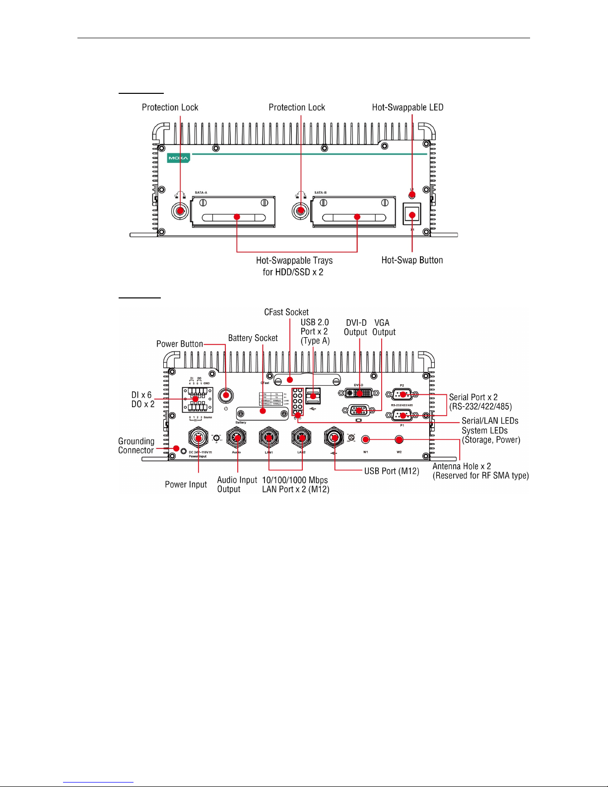
Appearance
Front View
Rear View
Page 9
Moxa MXNVR-RO Hardware Introduction
2-3
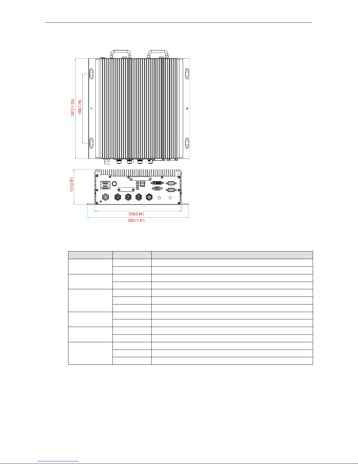
Dimensions
LED Indicators
LED Name LED Color LED Function
Power Green Power is on and functioning normally
Off Power is off, or has failed
Storage Yellow CFast card/HDD/SSD is transmitting data.
Off CFast card/HDD/SSD is not tr ansmitting data.
LAN (1, 2) Green 100 Mbps Ethernet mode
Yellow 1000 Mbps Ethernet mode
Off 10 Mbps or no activity
Tx (P1-P2) Green Serial ports P1-P2 transmitting data
Off Serial ports P1-P2 not transmitting data
Rx (P1-P2) Yellow Serial ports P1-P2 receiving data
Off Serial ports P1-P2 not receiving data
L1 Red Disks are running
Blinking Disks are unmounting
Off Disks are ready to be removed
Page 10
Moxa MXNVR-RO Hardware Introduction
2-4
Real Time Clock
The embedded computer’s real-time clock is powered by a lithium battery. We strongly recommend that you do
NOT replace the lithium battery on your own. If the battery needs to be changed, we suggest you contact the
Moxa RMA service team.
ATTENTION
There is a risk of explosion if the wrong type of batte ry is used. To avoid t his potential dange r, always use the
correct type of battery. Contact the Moxa RMA service team if you need to replace your battery.
Caution
Dispose of used batteries in a suitable manner.
Contact the manufacturer of your battery for more details.
Page 11

3
3. Hardware Connection Description
In this chapter, we show how to connect the embedded computers to the network and to a variety of common
devices.
The following topics are covered in this chapter:
Installing the MXNVR-RO-T
Wiring Requirements
Connecting the Power
Grounding the Unit
Connecting Data Transmission Cables
Connecting to a Serial Device
Connecting an Audio Input
Digital Input/Output
Connecting to a VGA Monitor
Connecting to a DVI-D Monit or
Connecting to the USB Ports
Installing an Internal Storage Device
Making a Storage Drive Hot-Swappable
Page 12
Moxa MXNVR-RO Hardware Connection Description
3-2
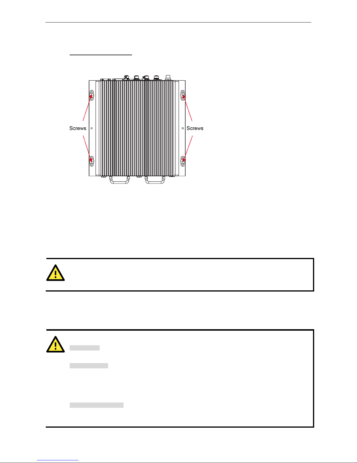
Installing the MXNVR-RO-T
Wall or Cabinet Mounting
The MXNVR-RO-T comes with two wall-mounting brackets. Use two screws per side to attach the MXNVR-RO-T
to a wall or cabinet.
Wiring Requirements
This section describes how to connect peripheral devices to the embedded computer.
You should read and follow these common safety precautions before proceeding with the installation of any
electronic device:
• Use separate paths to route wiring for power and devices. If power wiring and device wiring paths must
cross, make sure the wires are perpendicular at the intersection point.
ATTENTION
Do not run signal or communication wiring together with power wiring in the same wire conduit. To avoid
interference, wires with different signal characteristics should be routed separately.
• Use the type of signal transmitted through a wire to determine which wires should be kep t separate. The
rule of thumb is that wiring that shares similar electrical characteristics can be bundled together.
• Keep input wiring and output wiring separate.
• It is advisable to label the wiring to all devices in the system.
ATTENTION
Safety First!
Be sure to disconnect the power cord before installing and/or wiring your V2616A.
Wiring Caution!
Calculate the maximum possible current in
each power wire and common wire. Observe all electrical codes
dictating the maximum current allowable for each wire size.
If the current goes above the maximum ratings, the wiring could overheat, causing serious damage to your
equipment.
Temperature Cautio
n!
Be careful when handling the unit. When the unit is plugged in, the internal components generate heat, and
consequently the outer casing may feel hot to the touch.
Page 13
Moxa MXNVR-RO Hardware Connection Description
3-3
Connecting the Power
Connect the 24 to 110 VDC power line with M12 connector to the MXNVR-RO-T computer. If the power is
supplied properly, the Power LED will glow a solid green after 25 to 30 seconds.
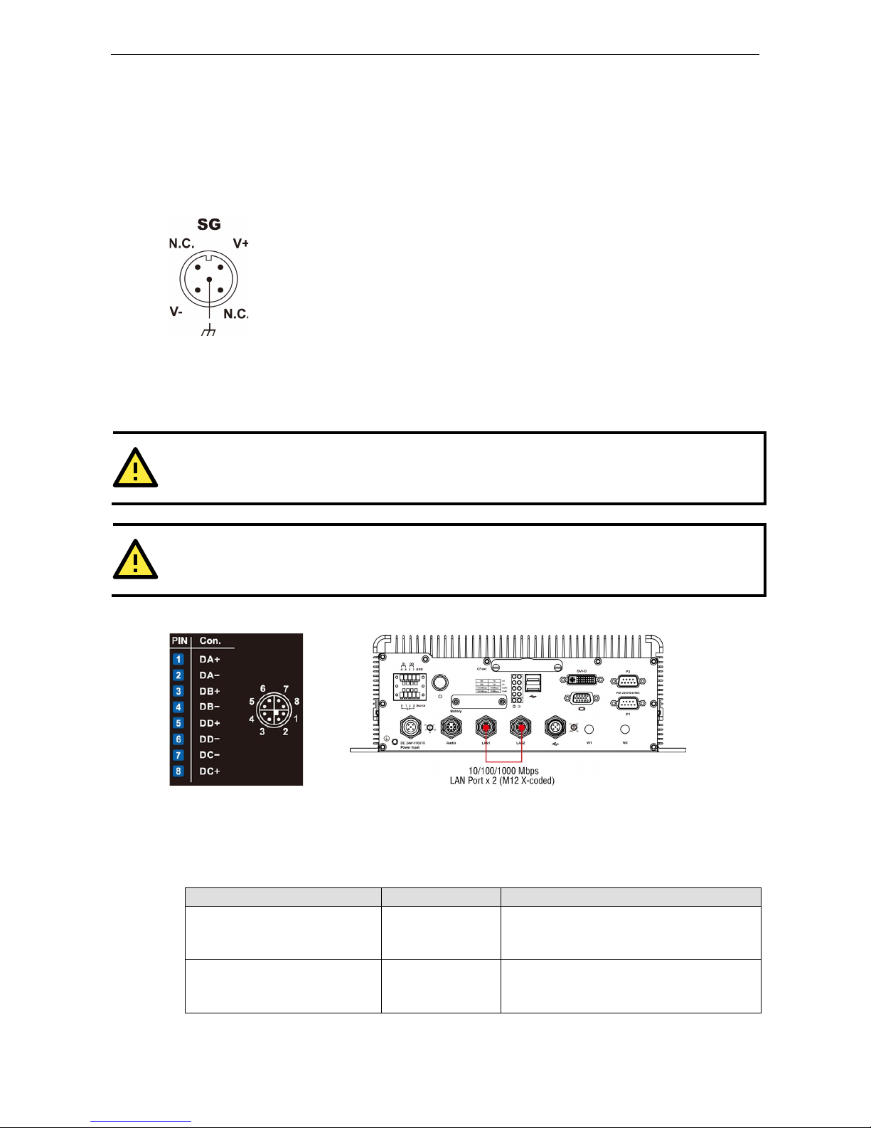
Grounding the Unit
SG:
The Shielded Ground (sometimes called Protected Grou n d
) contact is the central
pin of the power input connector. Connect the SG wire to an appropriately grounded metal
surface.
Connecting Data Transmission Cables
Two 10/100/1000 Mbps Ethernet ports using M12 X-coded connectors are located on the rear panel.
ATTENTION
Do NOT remove the
power supply during a BIOS upgrade, since doing so may cause the system to crash.
ATTENTION
When you use a USB drive larger than 4 GB, you will need to convert the file system type to FAT32.
The following figure shows the Ethernet port location on the rear panel.
Follow the steps below to connect an M12 X-coded cable:
1. Obtain an M12 X-coded cable.
The following table shows the Ethernet connector and cable options. For more information, please contact
your local Moxa sales representative.
Model Name Type Description
CBL-M12XMM8PRJ45-BK-100-IP67 Cable and connector 1-meter X-coded M12-to-RJ45 Cat-5E UTP
Gigabit Ethernet cable, 8-pin male M12
connector, IP67-rated.
M12X-8PMM-IP67 Connector Field-installation X-coded screw-in Gigabit
Ethernet connector, 8-pin male, M12
connector, IP67-rated.
Page 14
Moxa MXNVR-RO Hardware Connection Description
3-4
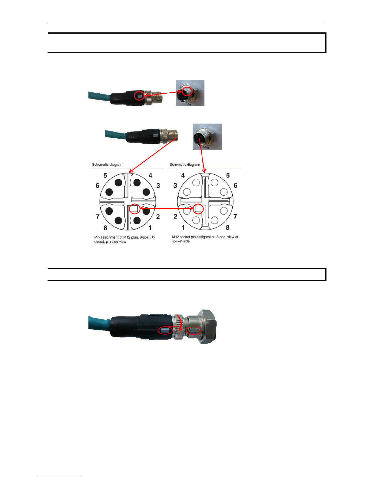
NOTE
For best performance and transmission quality, Moxa strongly recommends that you use cables and connectors
from Phoenix Contact.
2. Depending o n your M12 X-coded cable, orient the cable so that:
• The indicator on the M12 X-coded cable aligns w ith the key notch on the port, or
• The notch on the M12 X-coded cable pin core al ig ns with the notch on the port socket.
3. Connect the M1 2 X-coded cable to the port.
NOTE
Do NOT pus
h the M12 X-coded cable into the port with excessive force.
4. Turn to tighten the interlocking screw without using a mechanical tool (such a s a screw wrench).
Aligned
Interlock screw
Page 15
Moxa MXNVR-RO Hardware Connection Description
3-5
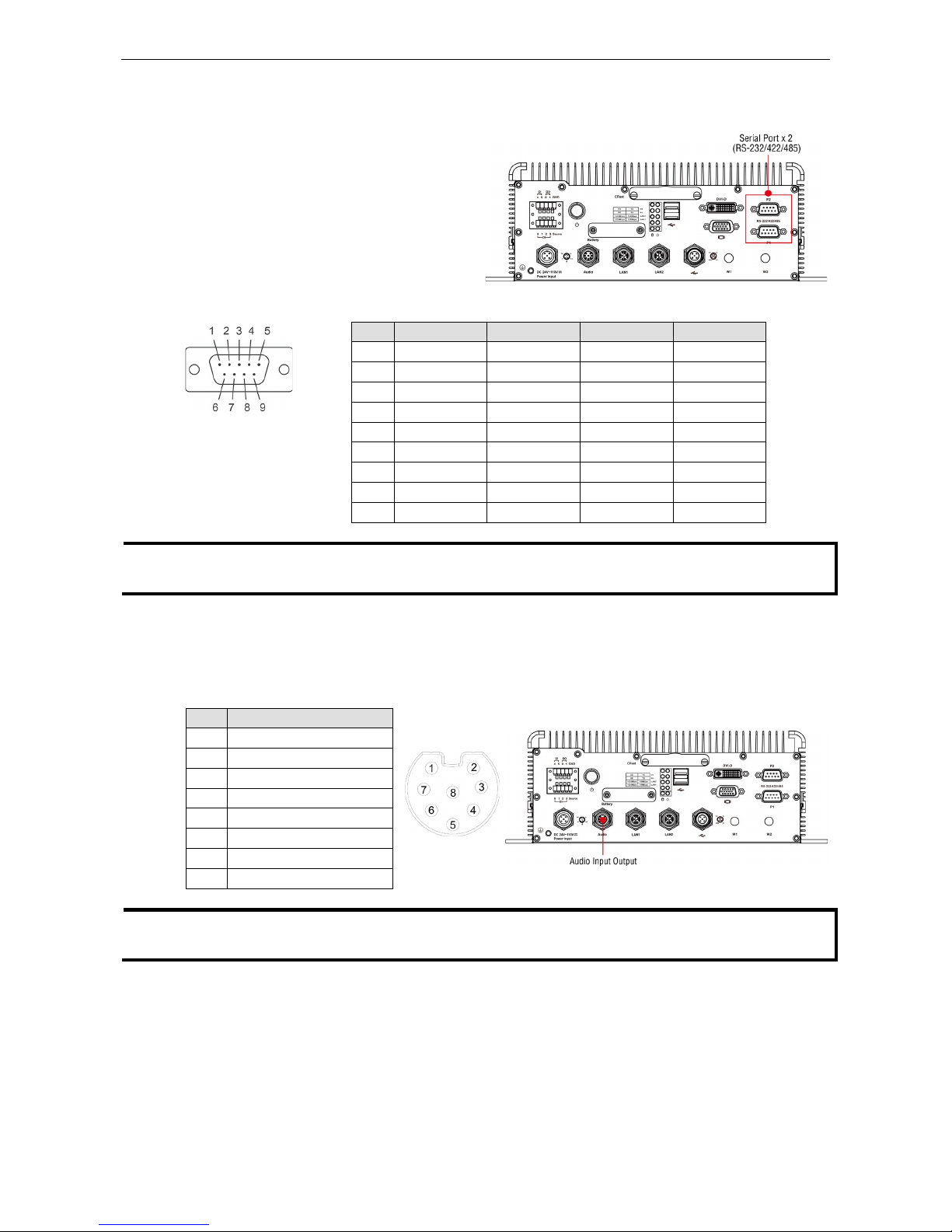
Connecting to a Serial Device
Use a serial cable to plug your serial device into
the embedded computer’s serial port. Serial ports
P1 to P2 have male DB9 connectors and can be
configured for RS
-232, RS-422, or RS-485 using
software. The pin assignments are shown in the
table at the top of the next page.
DB9
Male Port
RS
-232/422/485 Pinouts
Pin RS-232 RS-422 RS-485-4W RS-485-2W
1 DCD TxDA(-) TxDA(-) –
2 RxD TxDB(+) TxDB(+) –
3 TxD RxDB(+) RxDB(+) DataB(+)
4 DTR RxDA(-) RxDA(-) DataA(-)
5 GND GND GND GND
6 DSR – – –
7 RTS – – –
8 CTS – – –
9 – – – –
NOTE
This is the pin assignment for the comp uter
-side connectors on the MXNVR-RO-T. If you are wiring
peripheral
-side connectors for a serial cable, yo u w ill need to match the pin assignment.
Connecting an Audio Input
The MXNVR-RO-T comes with an M12 X-coded audio input/output connector, allowing users to connect a
speaker or earphones.
Pin Audio
1 Line-in, right
2 GND
3 Line in plug-in detected
4 Line-in, left
5 Line-out, left
6 Line out, plug-in detected
7 Line-out, right
8 GND
NOTE
This is the pin assignment for the comp uter
-side connectors on the MXNVR-RO-T shell. If you are wiring
peripheral
-side connectors for an audio cable, you will need to mirror the pin assignment.
Page 16
Moxa MXNVR-RO Hardware Connection Description
3-6
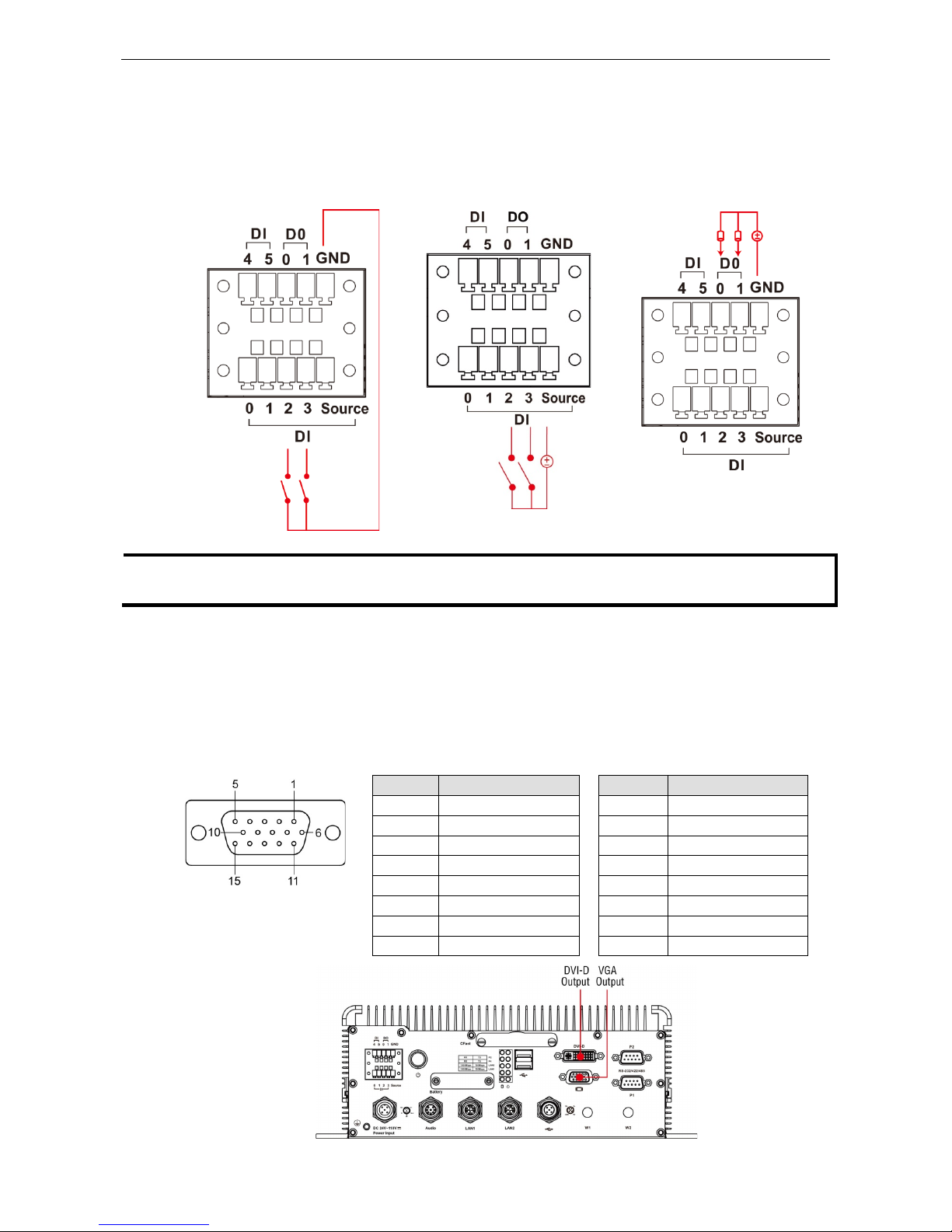
Digital Input/Output
The MXNVR-RO-T comes with a 6-ch digital input and a 2-ch digital output through a terminal block connector.
The pin assignments and the wiring methods are shown below.
DI Wiring: Dry Contact DI Wiring: Wet Contact DO Wiring: Dry Contact
NOTE
If you are using wet contacts, you must connect
source to power. In addition, both DI and DO can only be
wired as
sink types
Connecting to a VGA Monitor
The MXNVR-RO-T comes with a D-Sub 15-pin female connector on the front panel to connect a VGA monitor.
To ensure that the monitor image remains clear, be sure to tighten the monitor cable after connecting it to the
MXNVR-RO-T. The location and the pin a ssignments of the video outputs are shown in the diagram below.
DB15 Female Connector
Pin No. Signal Definition Pin No. Signal Definition
1 Red 9 VCC
2 Green 10 GND
3 Blue 11 NC
4 NC 12 DDC2B Data
5 GND 13 HSYNC
6 GND 14 VSYNC
7 GND 15 DDC2B Clock
8 GND
Page 17
Moxa MXNVR-RO Hardware Connection Description
3-7
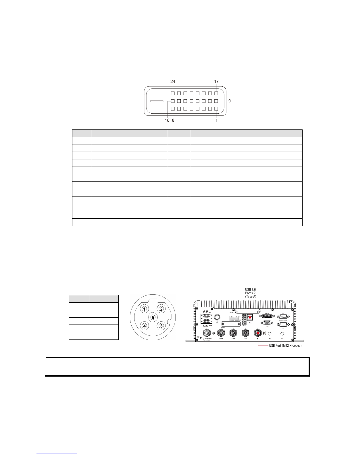
Connecting to a DVI-D Monitor
The MXNVR-RO-T computer also comes with a DVI-D output for DVI video. Use the cable to connect the DVI-D
output to the monitor; if you must rewire a cable, refer to the following table for pin assignments.
DVI-D Connector
Pin Signal Definition Pin Signal Definition
1 T.M.D.S. Data2- 13 N/C
2 T.M.D.S. Data2+ 14 +5V Power
3 T.M.D.S. Data2 Shield 15 Ground (return for +5V, HSync, and VSync)
4 N/C 16 Hot Plug Detect
5 N/C 17 T.M.D.S. Data 0 6 DDC Clock 18 T.M.D.S. Data 0 +
7 DDC Data 19 T.M.D.S. Da ta0 Shield
8 N/C 20 N/C
9 T.M.D.S. Data1- 21 N/C
10 T.M.D.S. Data1+ 22 T.M.D.S. Clock Shield
11 T.M.D.S. Data1 Shield 23 T.M.D.S. Clock+
12 N/C 24 T.M.D.S. Clock-
Connecting to the USB Ports
On its rear panel the MXNVR-RO-T has an X-coded M12 USB 2.0 port, as well as 2 type A USB 2.0 ports. The
hosts can be used for an external flash disk or hard drive for storing large amounts of data. You can also use
these USB hosts to connect to a keyboard or a mouse. See the following figures for the locations of the USB
ports and the M12 X-coded connector pin ass ig nment.
Pin USB
1 D+
2 D3 +5V
4 GND
5 N.C.
NOTE
This is the pin assignment for the comp uter
-side USB ports on the MXNVR-RO-T shell. If you are wiring
peripheral
-side connectors for a USB cable, you will need to mirror the pin assignment.
Page 18
Moxa MXNVR-RO Hardware Connection Description
3-8
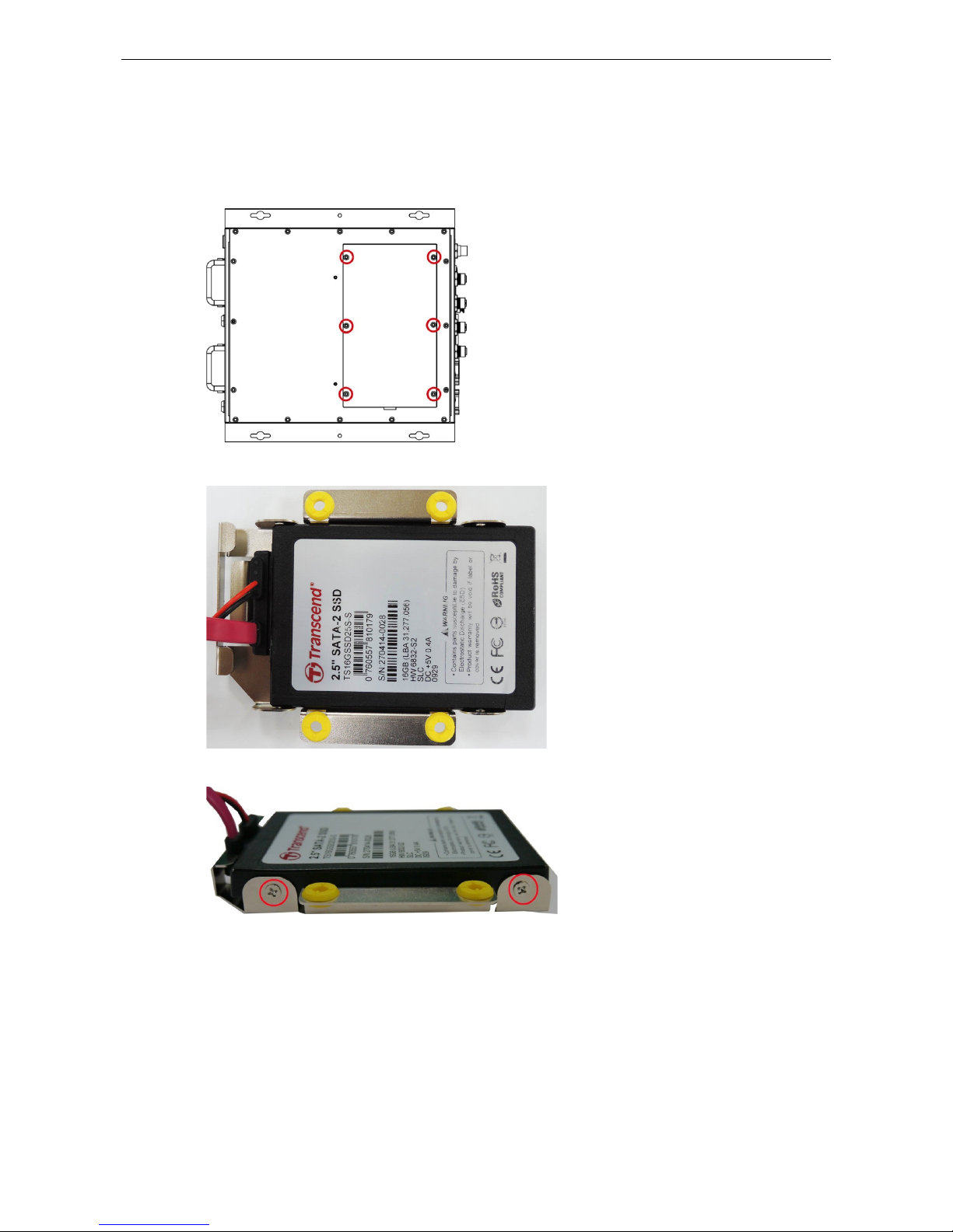
Installing an Internal Storage Device
The MXNVR-RO-T computer comes with an internal storage tray that allows users to install a 2.5-inch SATA
storage device, such as a hard disk or a SSD drive. Take the following steps to install your storage device.
1. Remove the 6 screws from the MXNVR-RO-T ’ s rear panel.
2. Install the hard disk onto the internal storage kit. Connect the cable and the connector.
3. Fasten the two screws on each side of the hard disk (total of four).
Page 19

Moxa MXNVR-RO Hardware Connection Description
3-9
4. Install the storage kit into the MXNVR-RO-T computer. Fasten four screws on the kit, and connect the cable
the power onto the MXNVR-RO-T’s main board.
5. Replace the cover onto the back of the computer.
Making a Storage Drive Hot-Swappable
MXNVR-RO-T computers come with 2 faceplates over the storage drive trays; users may attach storage drives
to the faceplates to install additional storage media, such as hard disks (HDD) or solid-state drives (SSD). The
following section gives instructions for installing the storage devices into the hot-swap trays.
1. The two faceplates on the front panel of the MXNVR-RO-T may be locked, for extra storage security.
2. Rota te the key counterclockwise to unlock the protection lock.
Page 20
Moxa MXNVR-RO Hardware Connection Description
3-10
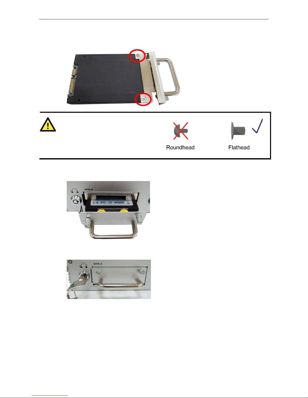
3. Pull ou t the faceplate by unscrewing the thumbscrews in the upper corners, and then remove the plate.
Fasten the storage drive to the faceplate flange as shown below, using the two flathead screws that were
shipped with your MXNVR-RO-T.
ATTENTION
To successfully fit the disk into the slo t, use the
flathead screws to fasten the hard disk to the tray.
Do not use the roundhead screws, since they may
prevent you from being able to insert the tray into
the slot.
4. Carefully align the drive with the drive slot, and gently insert the drive into the computer, taking care that
it slides smoothly and firmly into the SATA mounts.
5. When fin ished, turn the key clockwise to activ a te the lock and tighten the thumbscrew s. Use the same
method to install a hard disk in the second storage tray.
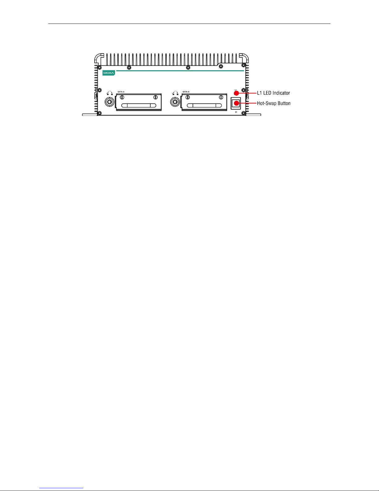
As these are hot-swappable storage trays, you can replace the storage disks while the computer is still powered
on. Follow these steps:
1. Push the hot-swap button, located on the lower right of the front panel.
2. Observe the L1 LED indicator (marked in the diagram below). When the LED starts blinking, the system will
start to unmount the storage d isk.
Page 21
Moxa MXNVR-RO Hardware Connection Description
3-11
3. When the LED stop s blinking, you may remove the storage drive.
4. After reinstalling the HDD please press the button again to remount.
Page 22

4
4. Access the MXNVR-RO-T Web-interface
This chapter includes information about how to access the MXNVR-RO-T Onboard Network Video Recorder for
the first time.
The following topics are covered in this chapter:
Overview of the MXNVR-RO-T Web Homepage
Network Settings
Time Setting
System Config
Software Upgrade
Download Tool
Page 23
Moxa MXNVR-RO Access the MXNVR-RO-T Web-interface
4-2
Overview of the MXNVR-RO-T Web Homepage
NOTE
The
MXNVR-RO-
T’s web homepage is best viewed at 1280 x 1024 screen resolution. We strongly recommend
using IE
10.0 (Microsoft Internet Explorer) or above to avoid incompatibility issues with the ActiveX Plug-in.
Page 24

Moxa MXNVR-RO Access the MXNVR-RO-T Web-interface
4-3
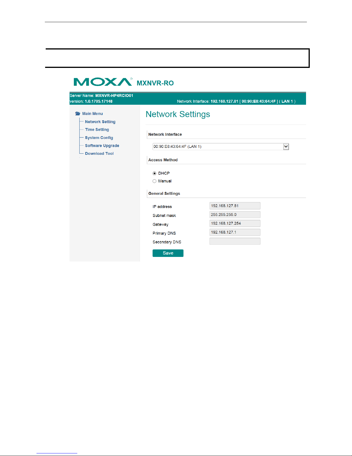
Network Settings
The Network Settings page includes some basic but important network configurations that enable the
MXNVR-RO-T to be connected to a TCP/IP network.
Default IP:
The preset IP for LAN 1 is 192.168.127.10.
The preset IP for LAN 2 is 192.168.127.11.
Network Interface
The MXNVR-RO-T product provides multiple network connection. The administrator can decide each network
interface connection setting.
Access Method
The MXNVR-RO-T supports the DHCP protocol, which means that the MXNVR-RO-T can get its IP address from
a DHCP server automatically when it is connected to a TCP/IP network. The administrator should determine if
it is more suitable to use DHCP, or to use a fixed IP address.
Setting Description Default
DHCP Get the IP address automatically from the DHCP server. Get IP address
automatically
Manual Use the IP address assigned by the Administrator.
NOTE
We strongly recommend assigning a fixed IP address to the
MXNVR-RO-T, since all of the functions and
applications provided by the
MXNVR-RO-T are active when the MXNVR-RO-
T is connected to the network. Use
DHCP to determine if the
MXNVR-RO-
T’s IP address may change when the ne tw ork environment changes, or
the IP a
ddress is occupied by other clients.
General Settings
Setting Description Default
IP address
Variable IP assigned automatically by the DHCP server, or fixed
IP assigned by the Administrator.
192.168.127.100
Subnet mask Variable subnet mask assigned automatically by the DHCP
server, or a fixed subnet mask assigned by the Administrator.
255.255.255.0
Page 25

Moxa MXNVR-RO Access the MXNVR-RO-T Web-interface
4-4
Setting Description Default
Gateway
Assigned automatically by the DHCP server, or assigned by the
Administrator.
Blank
Primary DNS
Enter the IP address of the DNS Server used by your network.
Then, you can input the VPort’s url (e.g.,
www.VPort.company.com) in your browser’s address field,
instead of entering the IP address.
Obtained
automatically from
the DHCP server, or
left blank in
non-DHCP
Secondary DNS
Enter the IP address of the DNS Server used by your network.
The VPort will try to locate the secondary DNS Server if the
primary DNS Server fails to connect.
Obtained
automatically from
the DHCP server, or
left blank in
non-DHCP
environments.
Time Setting
On the Time Setting page, administrators can set up the MXNVR-RO-T date and time, which is included in the
caption of all images.
Time zone
Setting Description Default
Time Zone Configure the time zone GMT
Date and Time
Setting Description Default
Manual Manually change the VPort’s date and ti me setting Keep current date
and time
Automatic Use the NTP server to set the VPort’s date and time setting
Page 26

Moxa MXNVR-RO Access the MXNVR-RO-T Web-interface
4-5
NOTE
Select the
Automatic option to force the VPort to synchronize automatically with timeservers over the
Internet. However, synchronization may fail if the assigned
NTP server cannot be reached, or t he VPort is
connected to a local network. Leaving the
NTP server blank will force the VPort to connect to default
timeservers. Enter either the Domain name or IP address format of the timeserver if the DNS server is
available.
You can configure two NTP servers as backups; the update interval can be configured from a minimum o
f 5
seconds up to one month.
Don’t forget to set the
Time zone for local settings. Refer to Appendix B for your region’s time zone.
System Config
This section shows the date and time and the HDD information of the system. The System Config page allows
you to export, import and control the server, which are listed by category. Administrators can also save this
information in a file (s ys_config.ini) by clicking the Export button, or import a file by clicking the Browse
button to search for a sys_config.ini file and then clicking the Import button to update the system
configuration quickly. By clicking the Factory Default button, the MXNVR-RO-T will be to reset to it s factory
default settings. By clicking the Reboot button, the MXNVR-RO-T will reboot, and by pressing the Shutdown
button the MXNVR-RO-T will shut down.
Software Upgrade
This section shows the information of the video sources that the MXNVR-RO-T is currently connected to. The
information includes:
Page 27

Moxa MXNVR-RO Access the MXNVR-RO-T Web-interface
4-6
Take the following steps to upgra d e the firmware:
Step 1: Press the Browse button to select the fir mware file.
NOTE
For the VPort, the firmware file extension should be .rom.
Step 2: Click on the Upgrade button to upload the firmware to the MXNVR-RO-T.
Step 3: The system will start the firmware upgrade process.
NOTE
Updating process will take about 2 minutes.
Upgrading the firmware will not change most of the original
settings.
Download Tool
Download Tool allows users to download the configuration tool straight from the web console. After
downloading the installation package it needs to be installed before configuring the MXNVR-RO-T.
Installation steps
Follow the steps below to install the MXNVR-RO-T configuration tool.
Step 1: choose the installer language
Page 28

Moxa MXNVR-RO Access the MXNVR-RO-T Web-interface
4-7
Step 2: start the installation process
Step 3: select installation components
Step 4: select the install destination folder
Page 29

Moxa MXNVR-RO Access the MXNVR-RO-T Web-interface
4-8
Step 5: wait for installation to complete
Step6 complete the installation process
Page 30

5
5. Configuration Tool
After installing the Configuration Tool, the next step is to configure the MXNVR-RO-T’s setting thro ugh the
configuration tool.
The following topics are covered in this chapter:
Overview of the MXNVR-RO-T Configuration Tool
NVR Management
System Setting
Device
Record
Event
Schedule
Search
Export
Remote
DriverView
Page 31
Moxa MXNVR-RO Configuration Tool
5-2
Overview of the MXNVR-RO-T Configuration
Tool
NOTE
The
MXNVR-RO-
T’s web homepage is best viewed at 1280 x 1024 screen resolution. We strongly recommend
using
IE 10.0 (Microsoft Internet Explorer) or above to avoid incompatibility with the ActiveX Plug-in.
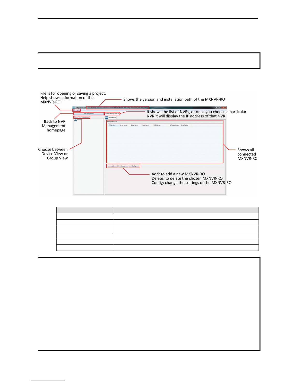
NVR Management
Manage NVR LIST
Setting Description
IP Address use broadcast to search for devices
Server Name set the research IP in a specific area
Group Name MXNVR-RO’s group name can be changed here
Model Name MXNVR-RO’s model name
MAC Address MXNVR-RO’s MAC address
Software Version MXNVR-RO’s software
NOTE
Administrator:
•
Add, open or save a project
•
Search connected MXNVR-RO
•
Login to MXNVR-RO
•
Add a new MXNVR-RO into a previous project
•
Remove a MXNVR-RO from a previous project
•
Change a MXNVR-RO settings
•
Check a MXNVR-RO’s event and log
Operator:
•
Open project
•
Login to MXNVR-RO
•
Check MXNVR-RO’s configuration setting
•
Check MXNVR-RO’s event and log
Page 32

Moxa MXNVR-RO Configuration Tool
5-3
Device & Group View
“Device View”: View of all the devices that are connected to the NVR.
“Group View”: View of all the dev ices that are connected to the Car.
Discover NVR
Discover NVR
There are 3 ways to search for an MXNVR-RO.
Setting Description
Broadcast Using broadcast to search for devices
Specify IP Find a device on a specific IP address
Unicast Range Set the research IP in a specific area
Page 33

Moxa MXNVR-RO Configuration Tool
5-4
Discover NVR
Setting Description
IP Address using broadcast to search for devices
Login Status Find a device on a specific IP address
Server Name Set the research IP in a specific area
Group Name MXNVR-RO’s group name and can be change here
Model Name MXNVR-RO’s model name
MAC Address MXNVR-RO’s MAC address number
Software Version MXNVR-RO’s software number
Enter Username and Password
Setting Description
User Name Login authorization’s user name
Password Login authorization’s password
Use password for all devices
with incorrect password
Use the username and password for the remaining devices that aren’t logged in
Authorization
Authorization
Setting Description
User Name Login authorization’s user name. Preset user name: admin.
Password Login authorization’s password. Preset password: moxamoxa.
Page 34

Moxa MXNVR-RO Configuration Tool
5-5
System Setting
Server Config
Sever Information
Setting Description
Server Name Display or rename the MXNVR-RO system
Group Name Display or rename the MXNVR-RO group’s name
Enable Record File
Authentication
Enable or disable the video files with s ig natures
System Shutdown
Setting Description
Reboot To reboot the MXNVR-RO system
Shutdown To shut down the MXNVR-RO
System Configuration
Setting Description
Export configuration When exporting the NV R c onfiguration file, a dialog box will pop up
Import Configuration path Choose the Configuration file Path for importing the configuration into
MXNVR-RO-T
… choose the path that will Import the Configuration into NVR
Import Configuration Import Configuration file in the path into NVR
Factory Default MXNVR-RO-T will set back to default
Page 35

Moxa MXNVR-RO Configuration Tool
5-6
Storage Setting
Storage Information
Setting Description
Storage Path Video files store path on disk
Total Space Total storage capacity on the disk
Available Space The total available storage capacity of the disk
Usage % The storage capacity on the disk that is being used
Safe Space Safe storage capacity on disk
Hardware Slot The disk slot that is being used
Modify Modify the currently selected disk group
Disk List
Setting Description
Hardware Slot The disk slot that is being used
Disk Name Name of the disk
Capacity The storage capacity of the disk
Status The recording status
Modify
Setting Description
Total & Available Displays the currently selected disk space and to tal space available
Safe Space Specifies the safe space retained on the disk, not to be used for recording
Page 36

Moxa MXNVR-RO Configuration Tool
5-7
Time Setting
Time zone setting
Setting Description Default
Time Zone Configure the time zone GMT
Date Time setting
Setting Description Default
Manual Manually change the NVR’s date and time setting Keep current date
and time
Automatic Use the NTP server to set the NVR’s date and time setting
NTP Client Set NVR as a NTP client and the time will be synced with t he
other NTP server
NA
Sync to server address Set NTP serv er address NA
Update Interval System time would be updated based on the time interval
that
is set
5 min
NTP Server Set NVR as a NTP server and allow other devices to get the
NVR's time
NA
Page 37

Moxa MXNVR-RO Configuration Tool
5-8
Network Setting
Network Setting
Setting Description Default
Network Interface Choose between different network interfaces
DHCP Get the IP address automa tically from the DHCP server DHCP
Manual Use the IP address assigned by the administrator
Security Setting
Account List
Setting Description
Name User account’s name
Group User permissions group is divided into administrator and operator
Description User defined description
Page 38

Moxa MXNVR-RO Configuration Tool
5-9
NOTE
•
User can add Administrator and
Operator's account, password, permissions, groups and custom description
•
The user can modify the Administrator and Operator passwords, permissions, groups and custom
description
•
Administrator and Operator can delete the account, except preset admin account and current account
Account Setting- New
Information
Setting Description
User Name User account’s name
Group Choose the permission group Administrator or Operator
Password Input the password
Confirm Password If a new password is typed in, you will need to retype the Confirm Password
before updating the new password.
Description User defined description
Account Setting - Modify
Information
Setting Description
User Name User account’s name
Group Choose the permission group Administrator or Operator
Password Input the password
Confirm Password If a new password is typed in, you will need to retype the Confirm Password
before updating the new password.
Description User defined description
Page 39

Moxa MXNVR-RO Configuration Tool
5-10
System Log
System Log
Setting Description
Log Source Choose between a recording service or authentication service
Date Choose the dates you want to search
Clear All Log Clear all saved logs
DateTime Show the date and time of the log
Priority Level of log
Source Source of the log
Text Description of the log
Log Count Total amount of log
Export Log Export log file to a specific location
Page 40
Moxa MXNVR-RO Configuration Tool
5-11
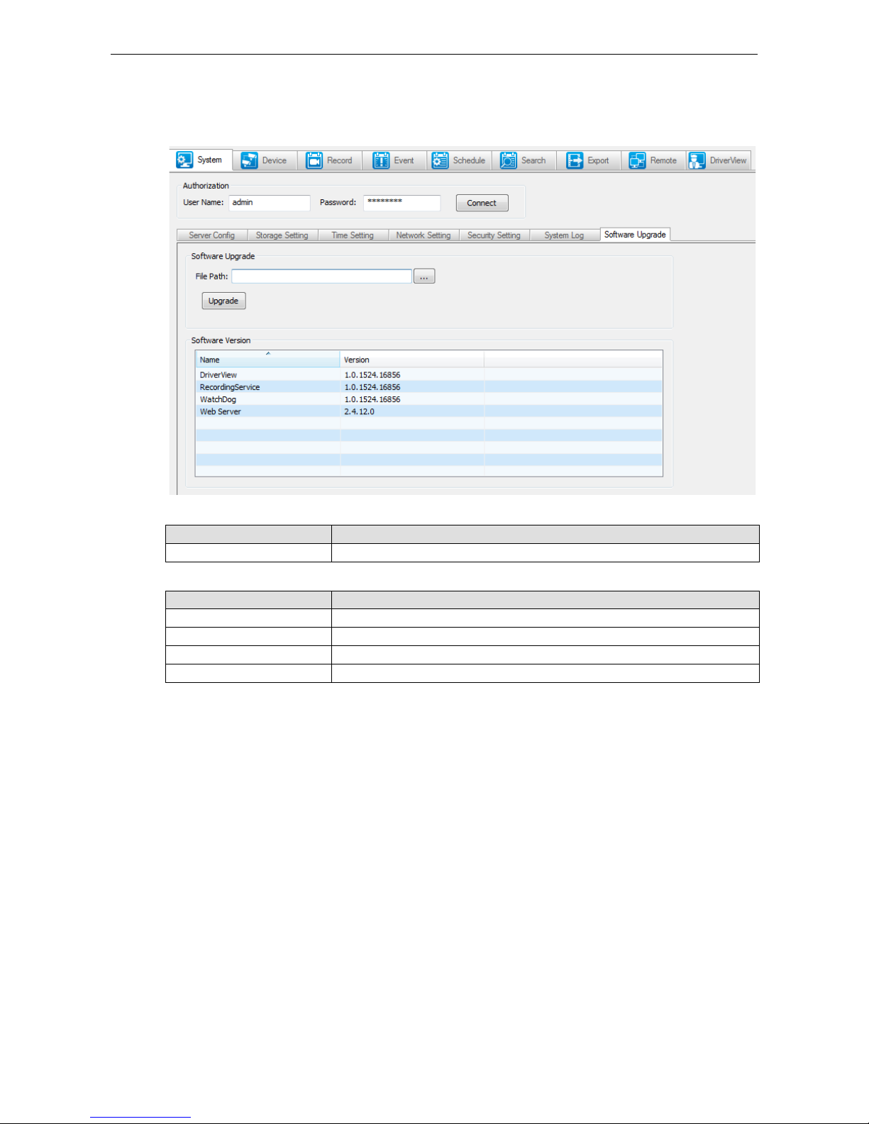
Software Upgrade
To upgrade the MXNVR-RO software it can be achieved by simply choosing file and then upgrade MXNVR-RO.
Software Upgrade
Setting Description
File Path Choose the Path for file to upgrade MXNVR-RO-T
Software Version
Setting Description
Driver View Driver View’s software version
Recording Service Record ing Service’s software version
Watch Dog Watch Dog’s software version
Web Server Web Serv er’s software version
Page 41

Moxa MXNVR-RO Configuration Tool
5-12
Device
All of the connected device and camera info will be shown here. If the camera's settings need to be modified it
can be done after choosing that spe cif ic ca m era.
Choosing a specific camera will show that camera’s information on a device list, and the streaming connection
information will be listed under connection info.
Device List
Setting Description
IP Address IP address o f the connected device
Device Name Name of the connected device
Group Name Group that the device is connected to
Model Name Model of the device
MAC Address MAC address of the device
Firmware Firmware version of the device
Connection Info
Setting Description
Stream Type Shows the connection type to the device
Stream Enable Shows the status of the stream connection
Video Resolution Video resolution of the connection
Video Codec The codec of the connection
Current FPS The FPS of the connection
Max FPS The Maximum FPS possible on the connection
Record Keep Days The amount of days the file will be kept for
NOTE
Administrator
:
Users can add, edit
, and delete NVR management of network video equipment.
Users can modify
the NVR network video management device connection settings.
Page 42

Moxa MXNVR-RO Configuration Tool
5-13
Add Devices
Discover Device
Setting Description
IP Address IP address o f the connected device
Login Status Login status of the connected device
Preview Preview live video of the connected device
Device Name Name of the connected device
Group Name Group that the device is connected to
Model Name Model name of the connected device
MAC address MAC address of the connected device
Firmware Firmware version of the connected device
Device Presetting
Setting Description
None Does not need to record video stream
Continuous Recording Choose the recoding rule
Streaming Presetting
Setting Description
Protocol type The protocol type of the device
Media type The media type of the device
Storage setting
Setting Description
Keep Days The amount of days the file will be kept for
Page 43
Moxa MXNVR-RO Configuration Tool
5-14
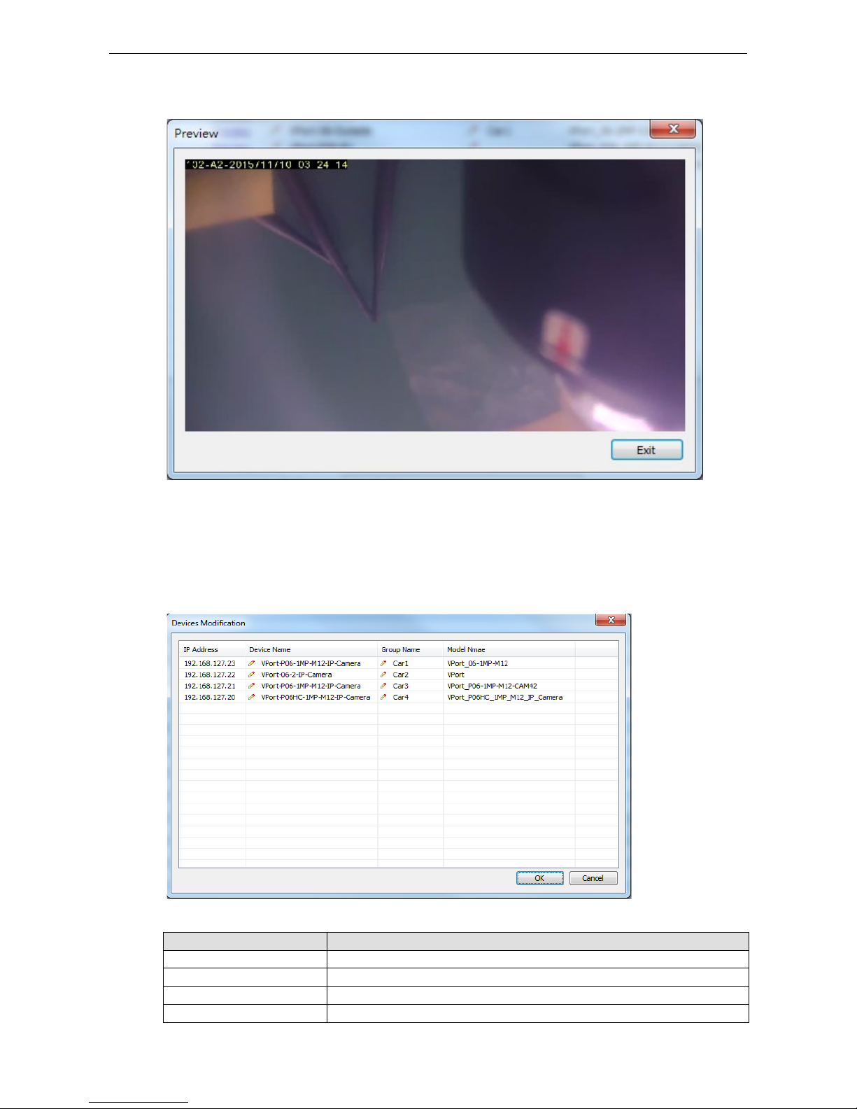
Preview Device
Preview function gives the user a quick look at the live view of the device that is connected. Also to check if it
is the right device that wants to connect.
Devices Modification
All of the settings can be modify here.
Device Modification
Setting Description
IP Address IP address o f the connected device
Device Name Name of the connected device
Group Name Group that the device is connected to
Model Name Model name of the device
Page 44
Moxa MXNVR-RO Configuration Tool
5-15
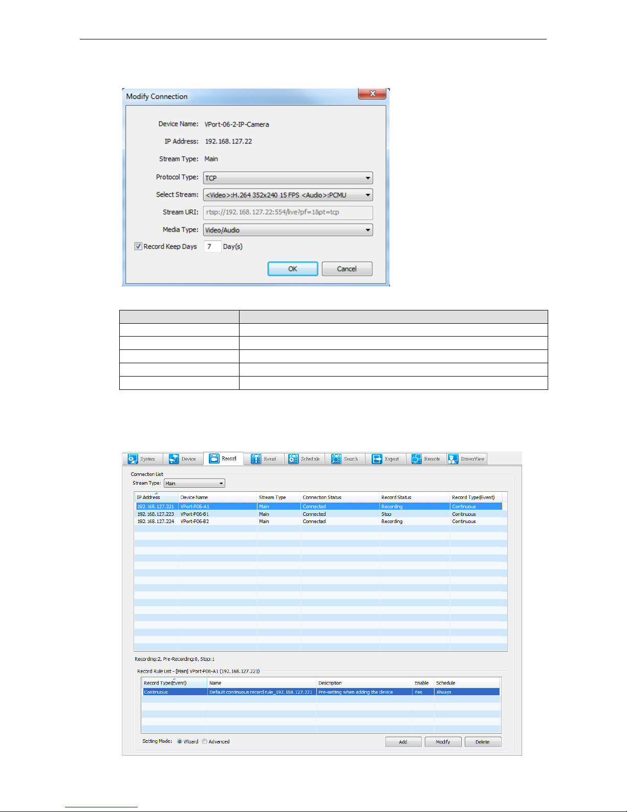
Modify Connection
Streaming Presetting
Setting Description
Protocol type The protocol type of the device
Select Stream Select streaming typ e
Stream URI Sh ows streaming’s URI
Media Type The media type of the device
Keep Days The amount of days the file will be kept for
Record
It shows all of the recording status and recoding rules of each selected camera.
Page 45

Moxa MXNVR-RO Configuration Tool
5-16
Connection List
Setting Description
Stream Type All: Shows both the main and seco ndary connections
Main: Shows only the main connection
Secondary: Shows only the secondary connection
Setting Description
IP Address IP address o f the connected device
Device Name Profile of the connection
Model Name Model name of the connected device
Connection Status The status of the connection
Record Status The status of the recording
Event Event type of the recoding
Disk Group Disk group that is going to keep the recorded video
Record Rule List
Setting Description
Record Type(Event) Event type that is going to trigger the reco rding
Name The name of the rule
Description Description of the recording rule
Enable Status of the event
Schedule Schedule of the recording event
Setting Mode
Setting Description
Wizard Guide to adding new recording rules
Advanced Advanced mode on adding new recording rule
NOTE
Administrator
can add, modify, and delete rules for connection of video.
Administrator can view the status of the connection and video streaming
.
Page 46

Moxa MXNVR-RO Configuration Tool
5-17
Event
All of the camera or NVR events are listed on this page, and you can also add new events here.
Lists all the event rules that have been set. Once a rule has been chosen the detailed information will be listed
below.
Rule List
Setting Description
Record Type(Event) Event type that is going to trigger the recording
Name The name of the rule
Description Description of the recording rule
Enable Status of the event
Schedule Schedule of the recording event
Information
Setting Description
Wizard Guide on addin g new r ecording rule
Advanced Advanced mode for adding new recording rule
Page 47

Moxa MXNVR-RO Configuration Tool
5-18
Rule Setting – Wizard mode
The wizard helps the user set the rule that describes the events obtained by the camera or NVR and also the
related actions.
Shows step & Summary of rule
setting
4 different wizard rule to choose
Control bottom
Page 48

Moxa MXNVR-RO Configuration Tool
5-19
Step1: Type
Type
Setting Description
Continuous Recording Event can only choose Continuous recording Action can only choose Record
Event Recording Event can cho ose any event except continuous recording.
Action can only choose recording
Event Trigger Actions Event can choo se an y event except Continuous recording
Action can choose any event except recording
Event Trigger Actions &
Record
Event can choose any event except continuous recording
All actions can be chosen
Page 49

Moxa MXNVR-RO Configuration Tool
5-20
Step2: Event
• Name: The name of this event
• Description: customers event descr ip tion
• Type: Show the current event type
• Continuous: When the type chosen is con tin uous recording, the event will be recorded.
• VPort DI
Device: to choose the DI trigger IP ca mer a
DI Index: can choose between 1 to 8
Initial: Initial DI status, can initial between Low and High
Page 50

Moxa MXNVR-RO Configuration Tool
5-21
• NVR DI
DI Index: can choose between 1 and 8
Initial: Initial DI status Low and High
Current: MXNVR-RO DI situation
• CGI
CGI Start: customer setting CGI Event trigger command
CGI Stop: customer setting CGI Event end trigger command
CGI Note: add note after CGI command
&Note= Note String
Note will show up in Event Search, CGI Note
http://<IP-Address>/cgi-bin/event.cgi?&Note=DoorOpen
• Tamper
Device: to choose the Tamper IP camera
Page 51

Moxa MXNVR-RO Configuration Tool
5-22
Step3: Action
Action List
• Name: Name of the action
• Action Type: Type of the action
• Action Description: Description of the action
Action Setting
• Name: Name of the action
• Description: Description o f the action
Bottom
• Add: Add a new action
• Modify: Modify the chosen action
• Delete: Delete the chosen action
• Clear All: Clear all the current action settings
• Record
Device: to choose the IP camera that will record
Record: time interval of recording
Page 52

Moxa MXNVR-RO Configuration Tool
5-23
• Snapshot
Device: To choose the Snapshot IP camer a
• CGI
CGI Start: customer settings CGI command
CGI Stop: customer setting CGI command
User Name/ Password: CGI comma n d’s username and password
• VPort DO
Device: to choose the DO control IP camera
DO Index: can choose between 1 to 8
Status: after the action the relay statue will change to either Open or Close
• NVR DO
DO Index: 1 to 8
Status: after the action the relay status will change to Close / Open
Current: current status of NV R DO
Page 53

Moxa MXNVR-RO Configuration Tool
5-24
• Notify Driver
Message: message that will show is the Driver’s View
Connection List: all the devic e that is Connected to MXNVR
Video Popup List: video Popup priority list
Up/Down: adjust the Video Popup sequence
Step4: Schedule
• Setting: set the Schedule Set ting as always, daily or weekly
• Modify / Add: add or modify the time Schedule
• Information: it shows the Scheduled time settings
Page 54
Moxa MXNVR-RO Configuration Tool
5-25
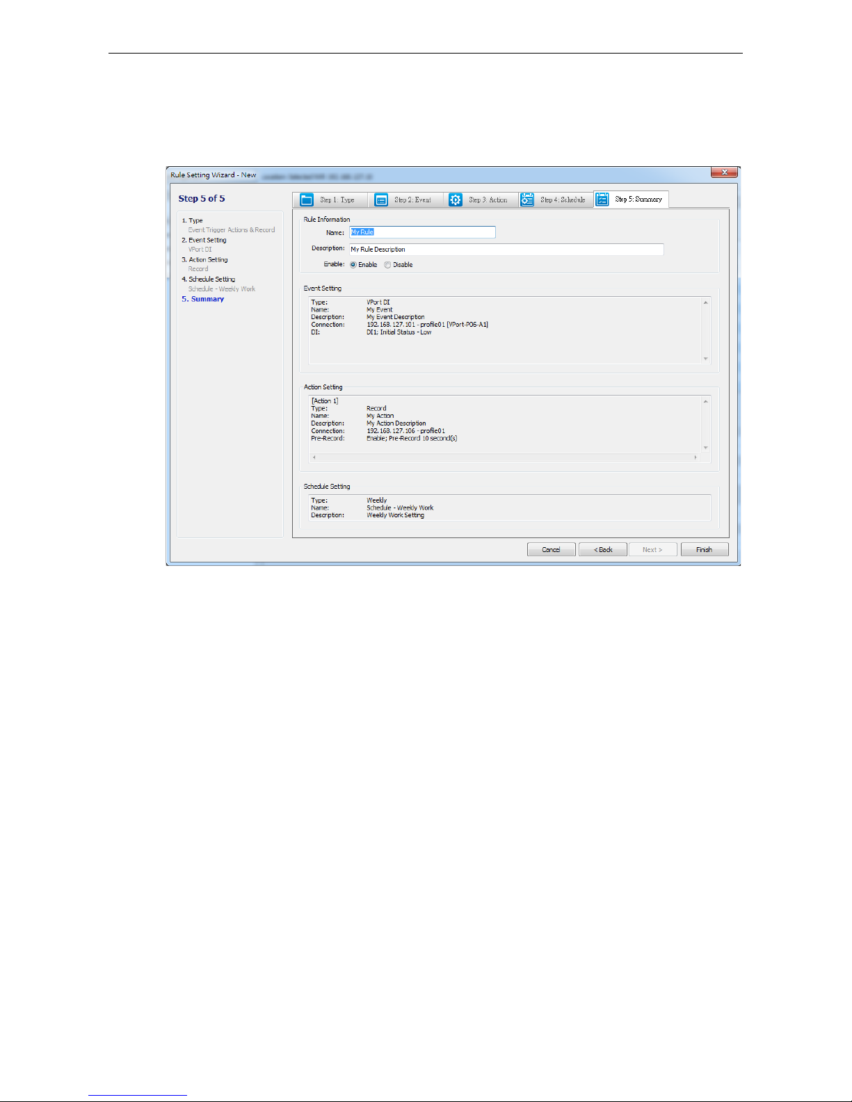
Step5: Summary
It shows all the information of the Ru le setting in the last step, and you can double check all the parameters
have been set, and decide to enable the ru le for the NVR.
Page 55

Moxa MXNVR-RO Configuration Tool
5-26
Rule setting – advance
Advanced Mode has 4 sectors that need to have the information filled in.
• Rule information
Name: name of the Rule
Description: descripti on of the Rule
Enable: choose enable or disable the Rule
• Step1: Event setting
Name: Name of the Event
Description: description of the Event
Event: multiple event to choose Continuous / VPort DI / NVR DI / CGI and Tamper, all categories are
same as Wizard Mode
• Step2: Action(s) setting
Name: Name of the Action
Description: Name of the Action
Action: multiple Action can be choose Record / Snapshot / CGI / VPort DO / NVR DO and Notify Driver,
all categories are same as Wizard Mode
• Step3: Schedule setting
Setting: event trigger’s Schedule setting
Description: show Schedule’s description
Page 56

Moxa MXNVR-RO Configuration Tool
5-27
Schedule
Schedule List
Setting Description
Name Schedule’s name
Type Schedule’s type, Daily or weekly
Description Description of the recording schedule
Information
Setting Description
Daily Every day apply daily schedule’s setting
weekly Every week apply weekly schedule’s setting
Page 57

Moxa MXNVR-RO Configuration Tool
5-28
Adding new schedule or modify the original schedule
Information
Setting Description
Schedule Name Schedule’s name
Schedule Description Description of the recording sched u le
Mode
Setting Description
Daily Using mouse drag to select the recording period
The red bar is the interval that has been set
The green bar is for new modifications
weekly
Date Daily or Weekly
Start Time Start of recording time
End Time End of recording time
Duration Continuous time of recording
Page 58

Moxa MXNVR-RO Configuration Tool
5-29
Search
Search the recording file or system log based on events or the action.
Event
Event Search
Setting Description
Start Date/Start Time Set the start search date and time
End Date/End Time Set the end search date and time
Event Type Choose sea rc h Event Type
Name Filter Type in search event filter name
Event result
Setting Description
Event Name Name of the event
Event Type Type o f the event
Start Time Start time of the event
End Time End time of the event
Duration Continuous time of the event
Status Status of t h e event
CGI Note Customer defined CGI Note will show in this se c tor
Export Log To export the log file, a pop out window will appear s o you can choose the path
for export log txt file
Page 59
Moxa MXNVR-RO Configuration Tool
5-30
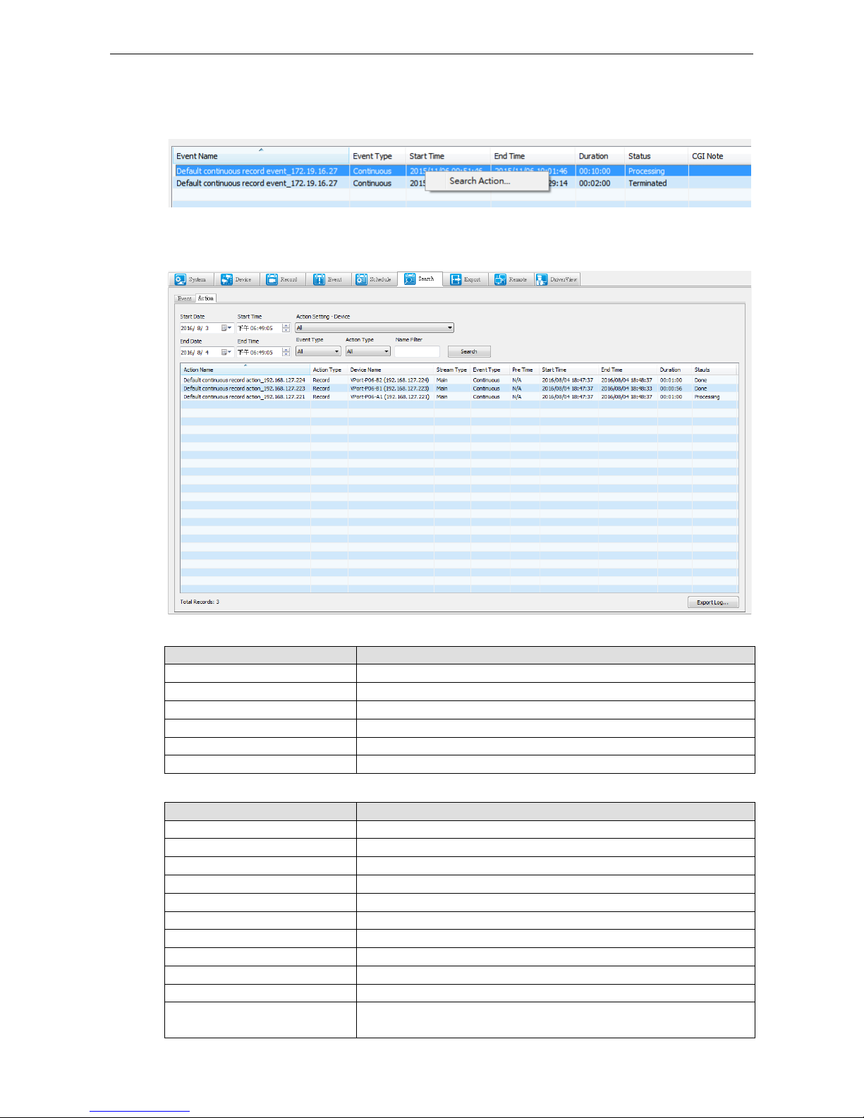
Search Action
Right click on the event will pop out a search action connection. Click on the search action to show the detail of
the event’s action.
Action
Action Search
Setting Description
Start Date/Start Time Se t the start date and time of the search
End Date/End Time Set the end date and time of the search
Device Name Search all action setting under the cho sen connection name
Event Type Choose search Event Type
Action Type Choose search Action Type
Name Filter Type in search event filter name
Action result
Setting Description
Action Name Name of the action
Action Type Type of the action
Device Name Action setting under the chosen connection name
Stream Type Type of the stream connection
Event Type Type of the event
Pre Time Shows start time of pre record
Start Time Start time of the action
End Time End time of the action
Duration Continuous time of the action
Status Status of the action
Export Log To export the log file, a pop out window will allow users to choose the path
for export log txt file
Page 60

Moxa MXNVR-RO Configuration Tool
5-31
Export File & Remote Playback
Right click on action will cause the Export File and Remote Playback to pop out. Click on Export File to export
the action file. Click on Remote playback to play the corresponding Action’s video.
Export
You can choose the files you need and export them from the NVR to the computer where the configuration tool
is installed.
Playback
Setting Description
Start Date Search start date
Start Time Search star t time
End Date Search end date
End Time Search end time
Device Name Search device’s connection name
Select All Select all the search results
Multi-Process Choose between 1 to 4 download processes
Speed Limitation Choose download speed between
128KB/256KB/512KB/1MB/2MB/4MB/8MB/16MB/32MB/unlimited
Export File Choose the path for exporting data
Page 61

Moxa MXNVR-RO Configuration Tool
5-32
Remote
Here are the functions for performing playback or live view at the remote side where the configuration tool is
installed.
Remote Playback
Playback
Setting Description
Start Date Search start date
Start Time Search start time
End Date Search end date
End Time Search end time
Device Search device
Main / Secondary Cho ose the str eam tha t is co nnect ed
Page 62
Moxa MXNVR-RO Configuration Tool
5-33
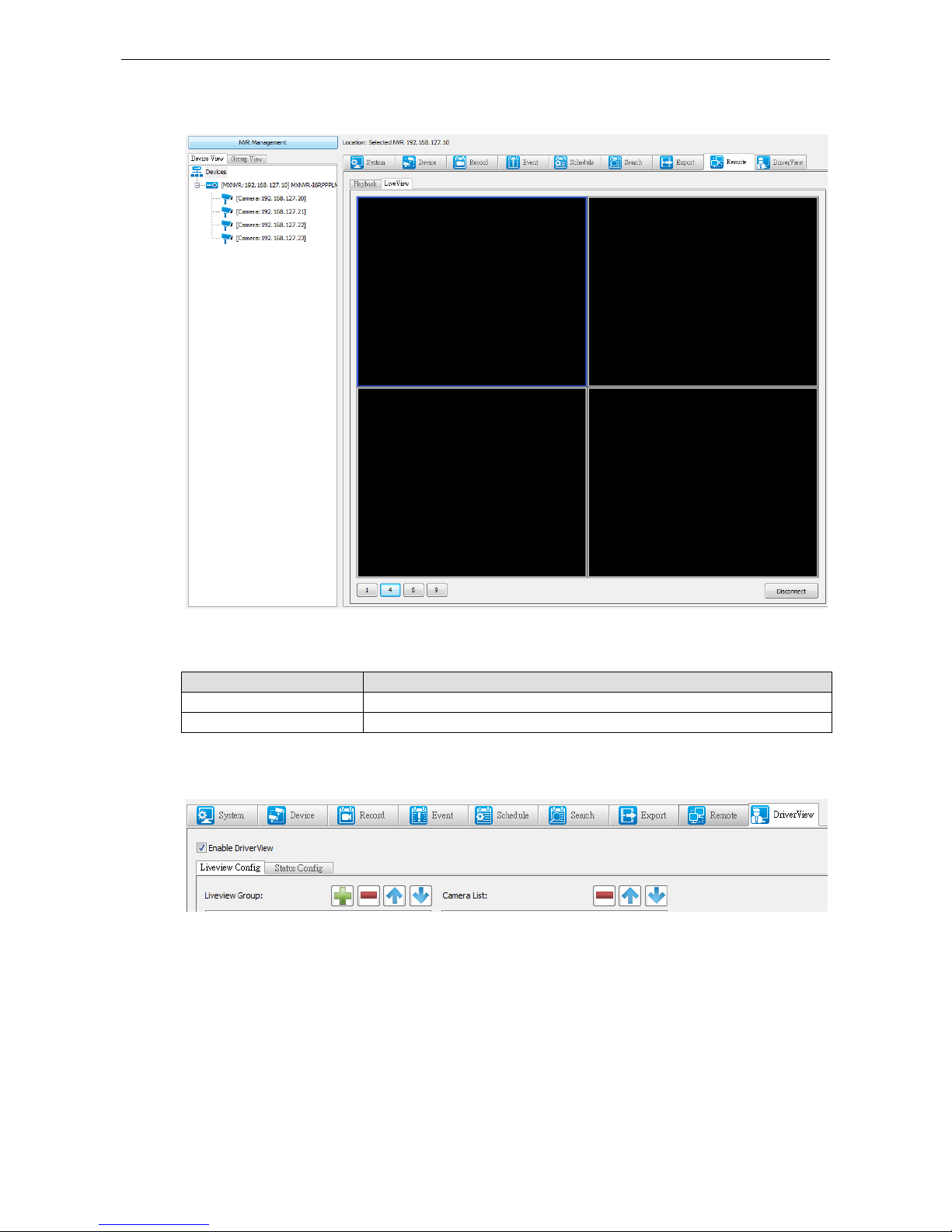
Remote Liveview
To see liveview on the black windows, you need to drag the device to the left window, so it can be displayed.
Connection List
Setting Description
“1”,”4”,”6”,”9”
Choose between different windows layout
Disconnect Disconnect the co nn ection to the device that is connected
DriverView
“Enable DriverView”: Enable or disable “Mo n ito r NV R” & “Liveview Camera” function.
Page 63

Moxa MXNVR-RO Configuration Tool
5-34
Liveview Config
To setup the Driverview's setting it can be chosen here.
Live View Group
Setting Description
Add new Group
Delete the Group
Move the Group up or down
Order Order of the Group
Group Name Group’s name
Sync From Group View Sync Group View’s Devi ce into liveviews’s group
Camera list
Setting Description
Delete the device
Move the Device up or down
Order Order of the devices
IP address Device’s IP address
Page 64

Moxa MXNVR-RO Configuration Tool
5-35
Status Config
Camera list
Setting Description
IP Address IP addres s o f the NVR that is connected
Page 65

6
6. DriverView
After configuring the MXNVR-RO-T’s setting through the configuration tool, the MXNVR-RO-T is ready to be
tested onboard through the driver view’s monitor.
The following topics are covered in this chapter:
Overview of the MXNVR-RO-T DriverView
Liveview
Status
Page 66
Moxa MXNVR-RO DriverView
6-2
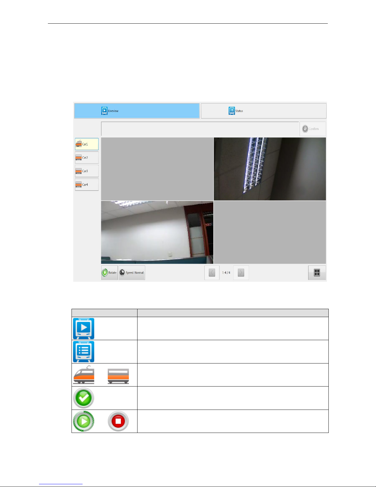
Overview of the MXNVR-RO-T DriverView
Liveview
The MXNVR-RO-T support the DHCP protocol, which means that the MXNVR-RO-T can get its IP address from
a DHCP server automatically when it is connected to a TCP/IP network. The administrator should determine if
it is more suitable to use DHCP, or to use a fixed IP.
Toolbar
Bottom Function
Switch to liveview
Switch to status
Choose between different cars
Confirm button for pop out warning message
Start and stop rotation play
Page 67

Moxa MXNVR-RO DriverView
6-3
Bottom Function
Rotation speed control
In the same car, Back and forth between different IP cameras
Switch to single view
Switch to quad view
Status
On the status it will show all of the chosen cameras and NVRs that are connected and the recoding status.
Setting Description
Car The name of the car
Device Name Name of the IP camera and the NVR devic e
IP address Each device’s IP address
Connected Device connection status , g reen light indicates connection red l ig ht indicates
disconnection
Recording The status of the IP camera, green light indicates the video is recording, the red light
indicates video is not recording
Page 68

A
A. Time Zone Table
The hour offsets for different time zones are shown below. You will need this information when setting the time
zone in automatic date/time synchronization. GMT stands for Greenwich Mean Time, which is the global time
that all time zones are measured from.
(GMT-12:00) Interna tional Date Line West
(GMT-11:00) Midway Island, Samoa
(GMT-10:00) Hawaii (GMT-09:00) Alaska
(GMT-08:00) Pacific Time (US & Canada), Tijuana
(GMT-07:00) Arizona
(GMT-07:00) Chihuahua, La Paz, Mazatlan
(GMT-07:00) Mountain Time (US & Canada)
(GMT-06:00) Centr al America
(GMT-06:00) Central Time (US & Canada)
(GMT-06:00) Guadalajara, Mexico City, Monterrey
(GMT-06:00) Saskatchewan
(GMT-05:00) Bogota , Li ma, Q uito
(GMT-05:00) Eastern Time (US & Canada)
(GMT-05:00) Indiana (Ea st)
(GMT-04:00) Atlantic Time (Canada)
(GMT-04:00) Caracas, La Paz
(GMT-04:00) Santiago
(GMT-03:30) Newfoundland
(GMT-03:00) Brasilia
(GMT-03:00) Buenos Aires, Georgetown
(GMT-03:00) Greenland
(GMT-02:00) Mid-Atlantic
(GMT-01:00) Azores
(GMT-01:00) Cape Verde Is.
(GMT) Casablanca, Monrovia
(GMT) Greenwich Mean Time: Dublin, Edinburgh, Lisbon, London
(GMT+01:00) Amsterdam, Berlin, Bern, Stockholm, Vienna
(GMT+01:00) Belgrade, Bratislava, Budapest, Ljubljana, Prague
Page 69

Moxa MXNVR-RO Time Zone Table
A-2
(GMT+01:00) Brussels, Copenhagen, Madrid, Paris
(GMT+01:00) Sarajevo, Skopje, Warsaw, Zagreb
(GMT+01:00) West Central Africa
(GMT+02:00) Athens, Istanbul, Minsk
(GMT+02:00) Bucharest
(GMT+02:00) Cairo
(GMT+02:00) Harare, Pretoria
(GMT+02:00) Helsinki, Kyiv, Riga, Sofia, Tallin n, Vilnius
(GMT+02:00) Jerusalem
(GMT+03:00) Baghdad
(GMT+03:00) Kuwait, Riyadh
(GMT+03:00) Moscow, St. Petersburg, Volgograd
(GMT+03:00) Nairobi
(GMT+03:30) Tehran
(GMT+04:00) Abu Dhabi, Muscat
(GMT+04:00) Baku, Tbilisi, Yerevan
(GMT+04:30) Kabul
(GMT+05:00) Ekaterinburg
(GMT+05:00) Islamabad, Karachi, Tashkent
(GMT+05:30) Chennai, Kolkata, Mumbai, New Delhi
(GMT+05:45) Kathmandu
(GMT+06:00) Almaty, Novosibirsk
(GMT+06:00) Astana, Dhaka
(GMT+06:00) Sri Jayawardenepura
(GMT+06:30) Rangoon
(GMT+07:00) Bangkok, Hanoi, Jakarta
(GMT+07:00) Krasnoyarsk
(GMT+08:00) Beijing, Chongqing, Hongkong, Urumqi
(GMT+08:00) Taipei
(GMT+08:00) Irkutsk, Ulaan Bataar
(GMT+08:00) Kuala Lumpur, Singapore
(GMT+08:00) Perth
(GMT+09:00) Osaka, Sapporo, Tokyo
(GMT+09:00) Seoul
(GMT+09:00) Yakutsk
(GMT+09:30) Adelaide
(GMT+09:30) Darwin
(GMT+10:00) Brisbane
Page 70

Moxa MXNVR-RO Time Zone Table
A-3
(GMT+10:00) Canberra, Melbourne, Sydney
(GMT+10:00) Guam, Port Moresby
(GMT+10:00) Hobart
(GMT+10:00) Vladivostok
(GMT+11:00) Magadan, Solomon Is., New Caledonia
(GMT+12:00) Auckland, Wellington
(GMT+ 12:00) Fiji, Kamchatka, Marshall Is.
(GMT+13:00) Nuku’alofa.
Page 71

B
B. Technical Specifications
Recording
No. of streams 8 VPort video/audio streams
Stream types H.264, MPEG4, and MJPEG
Video inputs Via Ethernet
Video file format AVI
Record mode Manual, sc hedule, alarm
Pre-alarm recording Up to 30 sec.
Post-alarm recording Up to 60 sec.
Searching
Search mode Camer a, date/time, event
Playback
Method Remote access, FTP file download
Remote access Playback via web browser or client software
FTP file downloads Playback via popular media players (requires FFDShow)
Storage
Disk interface 2 2.5” SATAII sockets
Note: Storage disks are not included . Users will need to purchase 2.5” hard disks or SSDs (Solid State Disk)
from hard disk vendors.
Network
Protocols TCP, UDP, HTTP, SMTP, FTP, Telnet, NTP, DNS, DHCP, UPnP, RTP, RTSP,
ICMP, IGMPv3, QoS (ToS), SNMP (V1/V2c/V3), DDNS, Modbus/TCP, 802.1X
Ethernet 1 auto-sensing 10/100/1000BaseT(X) RJ45 connector
Connection Max. 10
Audio ports
Audio output 1, 3.5mm, phone jack connector
Data Ports
COM ports 2 RS-232 or RS-422/485 port, with DB9 male connectors (for external
devices)
USB ports 1 USB 2.0 port, Type A
Console port 1 RS-232 RJ45 port
GPIO
Digital Inputs 6, source type, 0 to 5 VDC at 15 Hz Level 0: Close to GND
Level 1: Open
Digital Outputs 2, source type, 0 to 15 VDC, max. 20 mA
Level 0: 0 to 0.55 V
Level 1: 4.2 to 5.0 V
LED Indicators
STAT Indicates if system is booted up properly or not
PWR Power on/off
HDD Indicates if the hard disk is working or not
FAULT Can be configured for system alarm-- video loss, or network down.
Video 1/2/3/4/5/6/7/8 The status of video channel 1 to 8
LAN 10/100/1000 Mbps Ethernet link status
Page 72

Moxa MXNVR-RO Technical Specifications
B-2
Power
Input Voltage 1 24 VDC power input with the 3-pin terminal block co nnector
Power Consumption Max. of 20 watts (with 2 2.5” 500GB hard disk)
Physical Characteristics
Housing Metal
Dimensions (W x H x D) 440 x 44 x 325 mm (17.32 x 1.73 x 12.8 in)
Weight Appro. 3.6 Kg
Installation 19” rackmount
Security
Password User level password protection
Filtering By IP address
Authentication 802.1X
Environmental Limits
Operating Temperature S ta n dard models: 0 to 60°C (32 to 140°F)
Wide Temp. models: -40 to 75°C (-40 to 167°F)
Storage Temperature -40 to 85°C (-40 to 185°F)
Ambient Relative Humidity 5 to 95% (non-condensing)
Regulatory Approvals
Safety UL 60950-1
EMI FCC Part 15 Subpart B Class A, EN55032 class A
EMS EN61000-4-2 (ESD), Level 3
EN61000-4-3 (RS), Level 3
EN61000-4-4 (EFT), Level 2
EN61000-4-5 (Surge), Level 3
EN61000-4-6 (CS), Level 3
EN61000-4-8
EN61000-4-11
Shock IEC60068-2-27
Freefall IEC60068-2-32
Vibration IEC60068-2-6
Warranty
Warranty period 5 years
Details See www.moxa.com/warranty
System Requirements
CPU Pentium 4 2.4 GHz or above
Memory 512 MB memory or above
OS Windows XP/2000 with SP2 or above
Browser Internet Explorer 6.x or above
Multimedia DirectX9.0C or above
Software development kit
VPort SDK PLUS Includes VPort CGI commands, ActiveX Control, and API library for
customized applications or system integration for third-party developers
(the latest version or SDK is available for download from Moxa’s website )
 Loading...