

Page 1
Moxa Remote Connect Gateway
User’s Manual
Edition 1.0, December 2017
www.moxa.com/product
© 2017 Moxa Inc. All rights reserved.
Page 2

Moxa Remote Connect Gateway
User’s Manual
The software described in this manual is furnished under a license agreement and may be used only in accordance with
the terms of that agreement.
Copyright Notice
© 2017 Moxa Inc. All rights reserved.
Trademarks
The MOXA logo is a registered trademark of Moxa Inc.
All other trademarks or registered marks in this manual belong to their respective manufacturers.
Disclaimer
Information in this document is subject to change without notice and does not represent a commitment on the part of
Moxa.
Moxa provides this document as is, without warranty of any kind, either expressed or implied, including, but not limited
to, its particular purpose. Moxa reserves the right to make improvements and/or changes to this manual, or to the
products and/or the programs described in this manual, at any time.
Information provided in this manual is intended to be accurate and reliable. However, Moxa assumes no responsibility for
its use, or for any infringements on the rights of third parties that may result from its use.
This product might include unintentional technical or typographical errors. Changes are periodically made to the
information herein to correct such errors, and these changes are incorporated into new editions of the publication.
Technical Support Contact Information
www.moxa.com/support
Moxa Americas
Toll
-free: 1-888-669-2872
Tel:
+1-714-528-6777
Fax:
+1-714-528-6778
Moxa China (Shanghai office)
Toll
-free: 800-820-5036
Tel:
+86-21-5258-9955
Fax:
+86-21-5258-5505
Moxa Europe
Tel:
+49-89-3 70 03 99-0
Fax:
+49-89-3 70 03 99-99
Moxa Asia
-Pacific
Tel:
+886-2-8919-1230
Fax:
+886-2-8919-1231
Moxa India
Tel:
+91-80-4172-9088
Fax:
+91-80-4132-1045
Page 3

Table of Contents
1. Introduction ...................................................................................................................................... 1-1
2. Installation ....................................................................................................................................... 2-1
3. LED Indicators .................................................................................................................................. 3-1
4. Interfaces ......................................................................................................................................... 4-1
RESET Button ..................................................................................................................................... 4-2
WAN/LAN Ethernet Ports...................................................................................................................... 4-2
USB Interface ..................................................................................................................................... 4-3
Digital Input and Digital Output ............................................................................................................ 4-3
5. Management ..................................................................................................................................... 5-1
6. Activation Wizard .............................................................................................................................. 6-1
Activate a Gateway ............................................................................................................................. 6-2
Activation Option #1 ........................................................................................................................... 6-2
Activation Option #2 ........................................................................................................................... 6-4
Activation Option #3 ........................................................................................................................... 6-5
7. Gateway ............................................................................................................................................ 7-1
Activation Status ................................................................................................................................ 7-2
Tunnel Control.................................................................................................................................... 7-2
8. Network ............................................................................................................................................ 8-1
Scenario Setting ................................................................................................................................. 8-2
9. Local Device ...................................................................................................................................... 9-1
Local Device ....................................................................................................................................... 9-2
10. Service ............................................................................................................................................ 10-1
Service ............................................................................................................................................ 10-2
11. System ............................................................................................................................................ 11-1
Page 4
1
1. Introduction
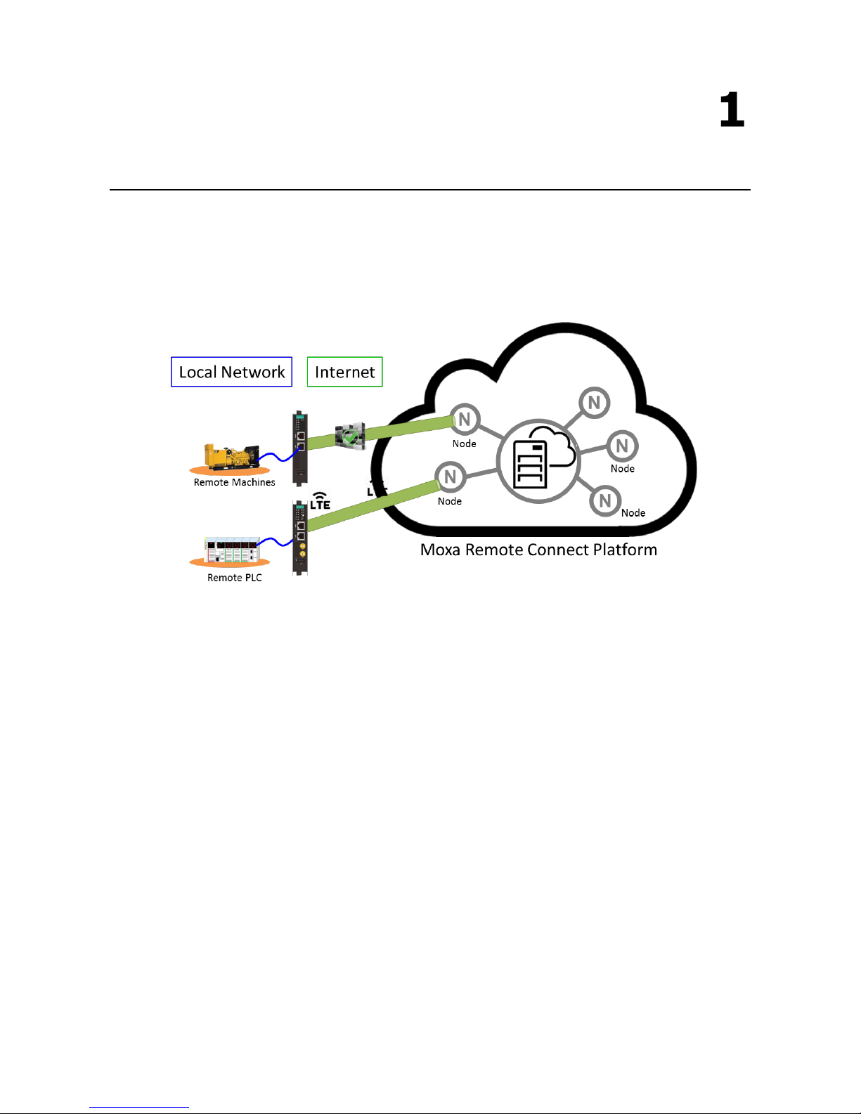
The MRC gateway is a 2-port Ethernet device that creates a connection between Ethernet equipment installed
at a remote site and the Moxa Remote Connect Platform. The remote connection normally occurs between a
SCADA server and a device that belongs to a service engineer.
Page 5
2
2. Installation
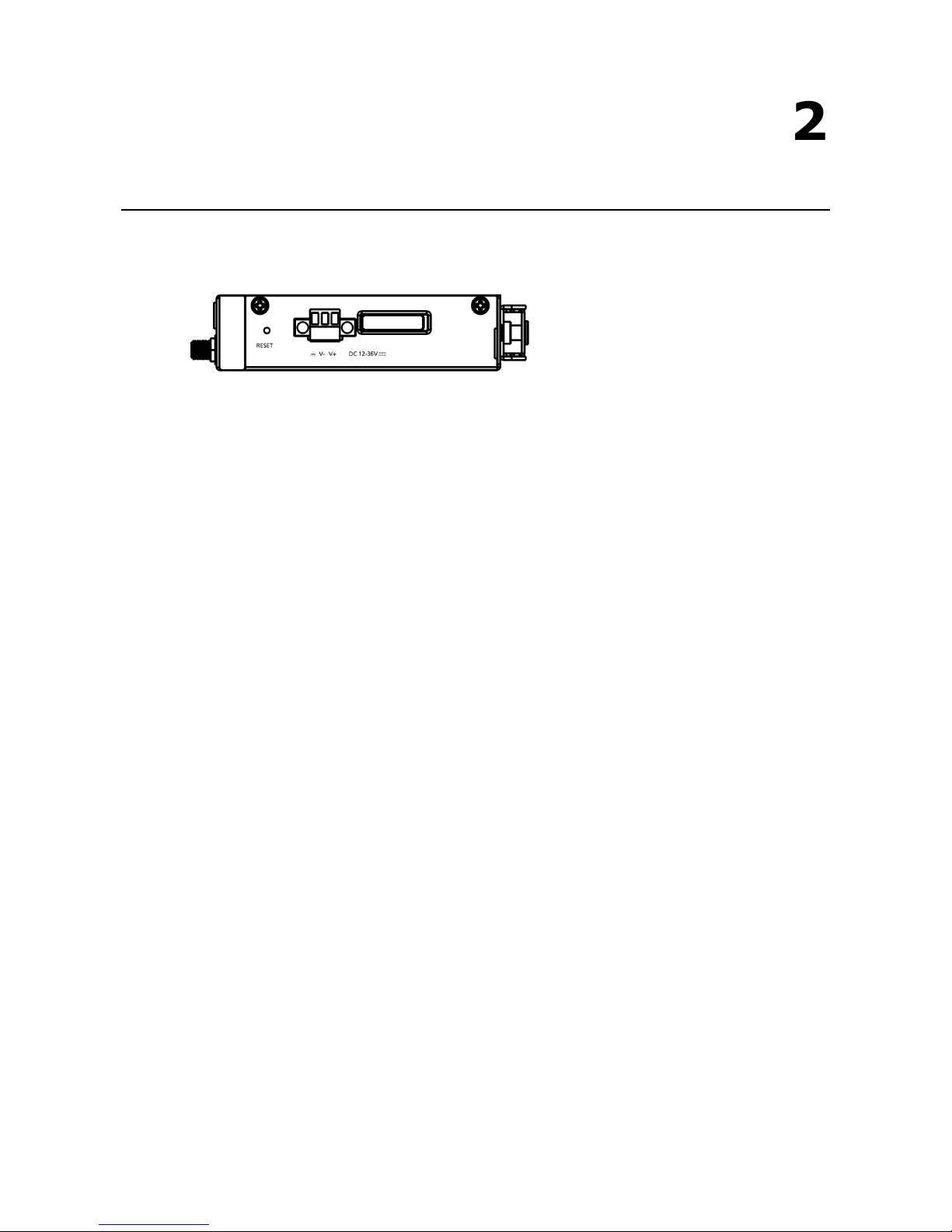
The MRC gateway supports a power input range from 12 to 36 VDC. Please ensure you use the correct power
supply to power on the gateway. The MRC gateway also has an embedded DIN-rail mounting kit to allow the
device to be mounted on a DIN-rail.
Page 6
3
3. LED Indicators
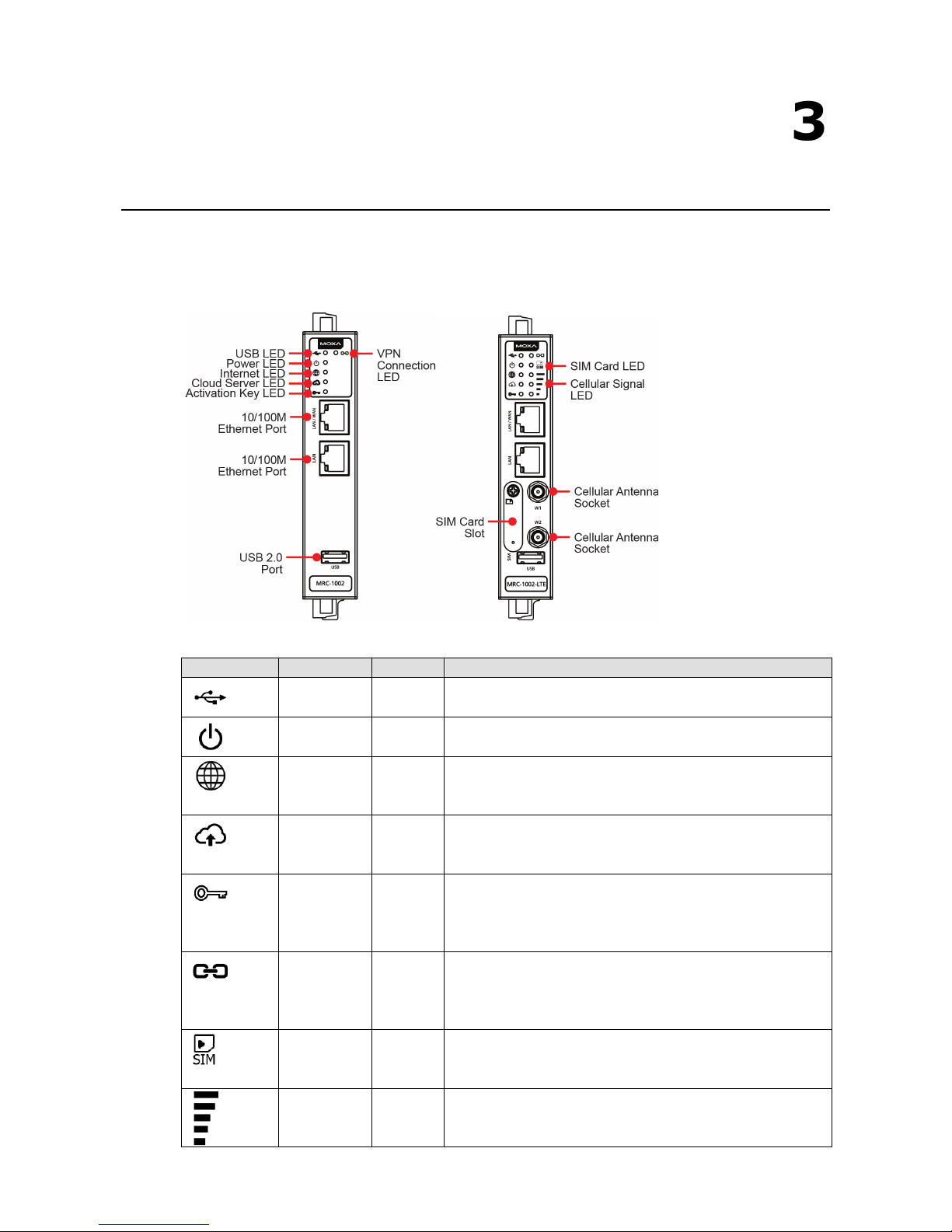
LED Symbol LED Name Color Function
USB Green Steady On: USB device is connected and working
Off: USB device is not connected
Power Green Steady On: The gateway is powered on
Off: The gateway is powered off
Internet Green
Off: WAN interface is not ready (DHCP failure, PPPoE failure, etc.)
Blinking: Testing the Internet connection
Steady On: Internet is available
Cloud Server Green Off: Not connected to the MRC Server
Blinking: Gateway is testing the MRC Server connectivity
Steady On: MRC Server is connected
Activation Key Green Off: There is no activation key inside the gateway
Blinking: The activation key is invalid
Steady On: The activation key is valid and the gateway is
activated
VPN Tunnel Green
Off: The VPN tunnel is down and remote access is not supported
Blinking: The gateway is trying to establish a VPN tunnel
Steady On: The gateway has successfully established a VPN
tunnel
SIM Card Green Off: No SIM card
Blinking: SIM card error
Steady On: SIM card is ready
Cellular Signal Green There are three LEDs that display the signal strength of the
cellular device.
3 LEDs On: Best signal quality
Page 7

Moxa Remote Connect Gateway LED Indicators
3-2
LED Symbol LED Name Color Function
2 LEDs On: Normal signal quality
1 LED On: Bad signal quality (may cause no Internet connection)
0 LED On: Very bad signal quality (no Internet connection)
Ethernet
Speed
Ethernet port is connected at 10M speed (amber) or 100
M speed
(green) speed
Page 8

4
4. Interfaces
The following topics are covered in this chapter:
RESET Button
WAN/LAN Ethernet Ports
USB Interface
Digital Input and Digital Output
Page 9
Moxa Remote Connect Gateway Interfaces
4-2
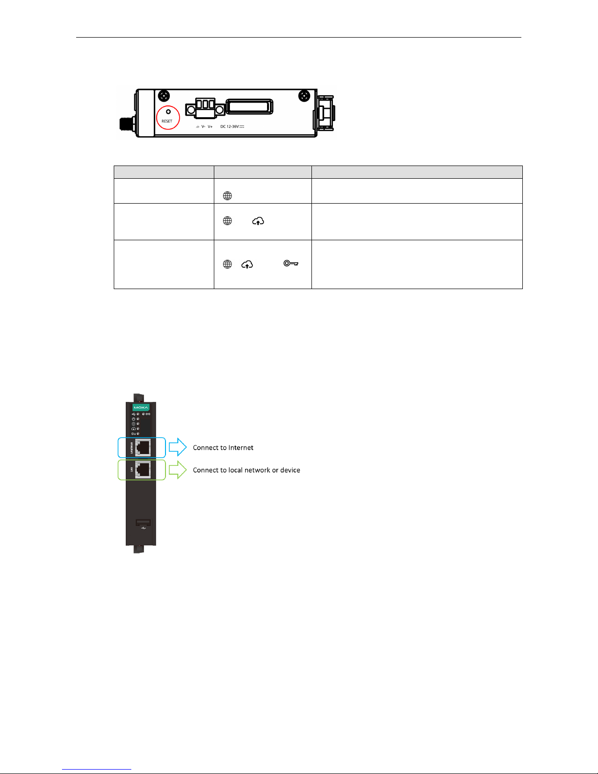
RESET Button
The RESET button can perform three functions depending on how long the button is depressed for.
Operation LED Behavior Action
Press and release
between 1 to 5 seconds
One LED is blinking
( )
Reboot the MRC gateway
Press and release
between 6 to 10 seconds
Two LEDs are blinking
( and )
Reset the login account and password to factory
default
(admin/moxa)
Reset to default LAN interface: 192.168.127.254
Press and release
between 11 to 15 seconds
Three LEDs are blinking
( , , and )
Reset all configurations and remove the activation key.
Note: If the RESET button is depressed for longer than
15 seconds, the MRC gateway will reboot without
changing any settings.
WAN/LAN Ethernet Ports
There are two Ethernet ports, WAN and LAN, on the MRC gateway. The WAN connects to the network that
provides Internet access to the MRC Server and the LAN connects to the field devices that require monitoring
or connections. Users can expand the number of LAN connections by adding a switch that provides more
Ethernet ports.
Page 10

Moxa Remote Connect Gateway Interfaces
4-3
USB Interface
The USB interface supports FAT/FAT32/NTFS-formatted USB dongles for key activation and tunnel connectivity
control.
Digital Input and Digital Output
There is one DI and one DO on the bottom of the MRC gateway. The DI is used to control the connection for the
tunnel to the MRC Server. The DO can be used as an alarm when the remote access tunnel is active.
Page 11
5
5. Management
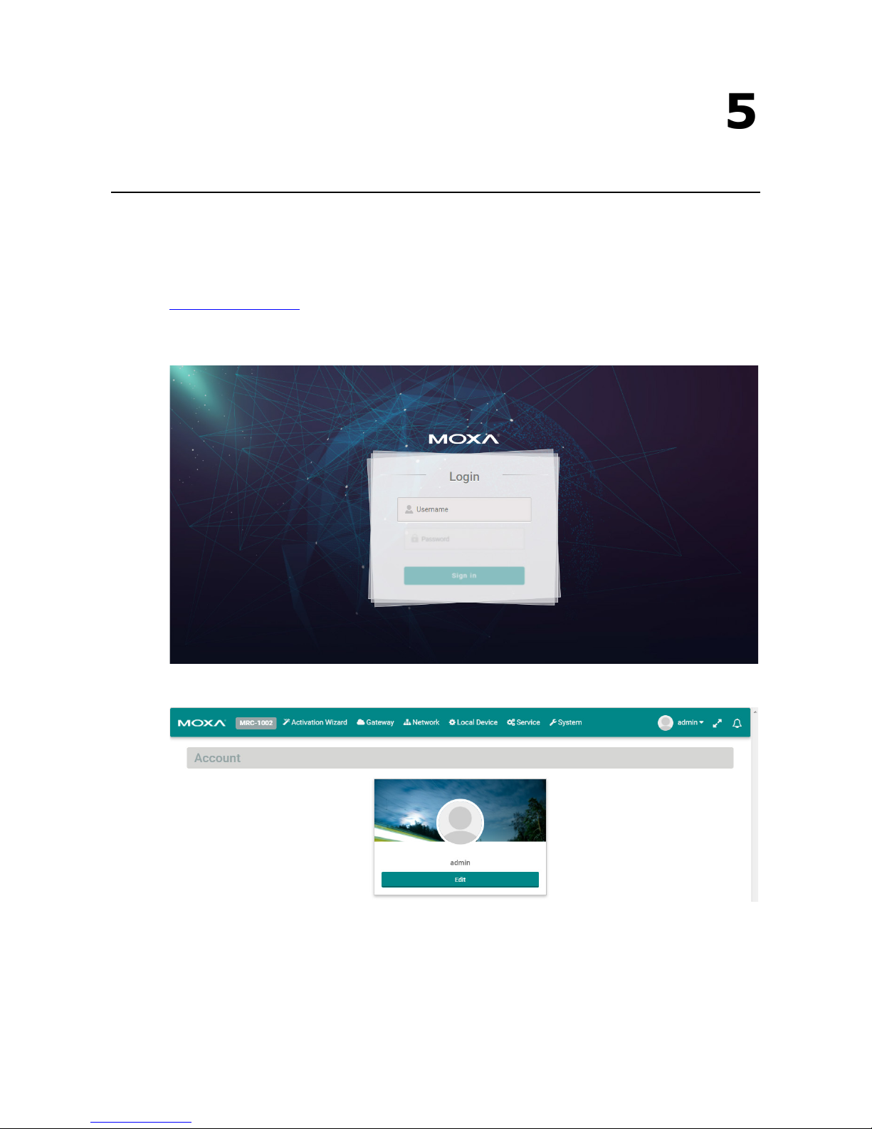
The MRC gateway provides a secure web console to perform configurations. After you have connected a laptop
to the LAN port, open your browser and type in the default web console address to access the web GUI:
http://192.168.127.254
Default username: admin
Default password: moxa
After you successfully login to the web console, you will see the management portal of the MRC gateway.
Page 12

Moxa Remote Connect Gateway Management
5-2
Click “Edit” to change the password.
Page 13

6
6. Activation Wizard
The following topics are covered in this chapter:
Activate a Gateway
Activation Option #1
Activation Option #2
Activation Option #3
Page 14

Moxa Remote Connect Gateway Activation Wizard
6-2
The MRC gateway has a wizard to assist users complete the configuration settings. There are three ways to
connect your MRC gateway to the MRC server.
Activate a Gateway
Below are the three options to register the MRC gateway.
Option Scenario
#1: I have an activation key You get a string from the MRC server administrator in order to
activate your gateway.
#2: I have an activation key in a USB
storage device
You get a file from the MRC server administrator in order to
activate your gateway.
#3: I do not have an activation key You get activating information from the MRC server
administrator
to manually activate your gateway.
Activation Option #1
When choosing option 1, users need to copy the string (activation key) and paste it into the MRC gateway.
Page 15

Moxa Remote Connect Gateway Activation Wizard
6-3
When choosing Option #1, follow the wizard to finish the gateway activation.
Input the activation key.
Select the time zone where you will install the gateway.
On the last step, please click “Initialize Now” to activate your gateway. (Remember to first connect your
gateway to the Internet.)
Page 16

Moxa Remote Connect Gateway Activation Wizard
6-4
Activation Option #2
When choosing Option #2, the MRC gateway will execute the auto configuration exchange with the MRC server.
Users should insert the USB drive that has the activation file stored on it. Then, follow the wizard to finish
activating your gateway.
Confirm your USB dongle has the correct activation key installed.
Select the time zone where you will install the gateway.
Page 17

Moxa Remote Connect Gateway Activation Wizard
6-5
On the last step, please click “Initialize Now” to activate your gateway. (Remember to first connect your
gateway to the Internet.)
Activation Option #3
When choosing option #3, you need to fill in all the necessary information retrieved from the MRC Server
administrator step by step.
Page 18

Moxa Remote Connect Gateway Activation Wizard
6-6
Step 1:
Input the MRC server IP address or domain name, service port, the Group Code, and a user-defined gateway
name. The gateway name must be unique in the MRC server. If activation is not successful, it is possible that
you registered your gateway with an existing name already stored in the MRC server. If you have any further
issues please contact your MRC server administrator.
Item Description
Server IP Address/Port The IP Address or the host domain name and the service port of the MRC
server.
Group Code The unique code to register the MRC gateway to the device group in the MRC
server.
Gateway Name The unique name of the MRC gateway within the same device group in the
MRC Server.
NOTE
The Group Code is provided by your MRC Server administrator. If you are the MRC Server administrator, please
check “Group Code” in the MRC Server.
Step 2:
Choose the network scenario for your gateway’s Internet installation.
Page 19

Moxa Remote Connect Gateway Activation Wizard
6-7
Mode Scenario
WAN-LAN Mode Connect an external ADSL modem, cable modem, or Internet WIFI router to
establish remote access.
WAN-LAN Mode with NAT Use the existing factory network to access the Internet in order to establish
remote access. Keep the device communicating to the factory network by using
NAT.
Transparent-LAN Mode Use the existing factory network to access the Internet in order to establish
remote access. Keep the LAN device communication transparent to the factory
network.
Cellular-WAN Mode Use cellular as Internet access. The two Ethernet ports are both LAN ports that
can be used for connecting to local devices.
Step 3:
Select the Internet Access method for your MRC gateway.
WAN-LAN Mode, WAN-LAN Mode with NAT, Transparent-LAN Mode:
Page 20

Moxa Remote Connect Gateway Activation Wizard
6-8
Setting Static IP
Setting DHCP
Page 21

Moxa Remote Connect Gateway Activation Wizard
6-9
Setting PPPoE
Page 22

Moxa Remote Connect Gateway Activation Wizard
6-10
Cellular-WAN Mode:
NOTE
To ensure the stability of cellular connection, please enable "Cellular Keep Alive" and "Cellular Watchdog"
1) "Cellular Keep
Alive" keeps checking the cellular availability and once it fails, the MRC gateway will try
to reconnect to the cellular base station.
2) "Cellular Watchdog" keeps monitoring the internal cellular module status and once the module is
abnormal, the MRC gateway will reset the module.
Step 4:
Input the LAN settings and the management IP for your MRC gateway. The MRC gateway’s management IP and
subnet must be the same as the network where your local devices are located.
Page 23

Moxa Remote Connect Gateway Activation Wizard
6-11
Step 5:
Configure your local devices for remote access. Click “ ” to add a local device.
Input the name of a local device and its IP address. Select “Ping Check” or “Port Link” for the MRC gateway to
check the health status of your device by PING or Port Link On/Off events. You can disable the Health Check
function if you want.
Users can configure a maximum of 25 local devices for remote access through the MRC Suite.
Page 24

Moxa Remote Connect Gateway Activation Wizard
6-12
Step 6:
Select the time zone where you will install the gateway.
On the last step, please click “Initialize Now” to activate your gateway. (Remember to first connect your
gateway to the Internet.)
Page 25

7
7. Gateway
The following topics are covered in this chapter:
Activation Status
Tunnel Control
Page 26

Moxa Remote Connect Gateway Gateway
7-2
Activation Status
On the “Gateway” settings page, you can check the activation status of your MRC gateway. You can also
configure the remote access capability of your MRC gateway.
Tunnel Control
Users can configure the method for how the MRC gateway establishes a tunnel for remote access.
Click on “ ” to change the tunnel control settings. There are three tunnel control options:
Option Description
Permanent Connection The MRC gateway automatically establishes the tunnel for remote access
whenever a connection to the Internet is available.
Controlled by USB key The MRC gateway initializes the tunnel for remote access only when a USB dongle
(loaded with the gateway’s activation key) is inserted into the gateway.
Controlled by DI ON The MRC gateway
initializes the tunnel for remote access only when a DI (digital
input) has been detected.
Page 27

8
8. Network
The following topic is covered in this chapter:
Scenario Setting
Page 28

Moxa Remote Connect Gateway Network
8-2
Users can change the network scenario settings and check the WAN/LAN status from the Network settings
page.
Scenario Setting
Click “ ” to change the tunnel control settings and click “Next” to continue inputting settings.
Mode Scenario
WAN-LAN Mode Connect an external ADSL modem, cable modem, or Internet WIFI router to
establish remote access.
WAN-LAN Mode with NAT Use the existing factory network to access the Internet in order to establish
remote access. Keep the device communicating to the factory network by using
NAT.
Transparent-LAN Mode Use the existing factory network to access the Internet in order to establish
remote access. Keep the LAN device communication transparent to the factory
network.
Cellular-WAN Mode Use cellular as Internet access. The two Ethernet ports are both LAN ports that
can be used for connecting to local devices.
WAN-LAN Mode:
Page 29

Moxa Remote Connect Gateway Network
8-3
Step 1: Setup Internet access
Page 30

Moxa Remote Connect Gateway Network
8-4
Setting Static IP
Setting DHCP
Setting PPPoE
Step 2: Setup the management IP address for LAN (must be the same subnet as the local network devices).
Page 31

Moxa Remote Connect Gateway Network
8-5
Click “Next” and wait for the configurations to change.
WAN-LAN Mode with NAT:
Page 32

Moxa Remote Connect Gateway Network
8-6
Step 1: Setup Internet access.
Step 2: Setup management IP address for LAN (must be the same subnet as local network devices).
Click “Next” and wait for the configurations to change.
Page 33

Moxa Remote Connect Gateway Network
8-7
Transparent-LAN Mode:
Step 1: Setup the unified interface for Internet access and LAN management IP address (must be the same as
local devices’ subnet).
Click “Next” and wait for the configurations to change.
Page 34

Moxa Remote Connect Gateway Network
8-8
Cellular-WAN Mode:
In this mode, the two Ethernet ports are operating as two LAN ports and your MRC gateway will use cellular to
access the Internet.
Step 1: Setup cellular for Internet access. There are two pre-defined carriers in the system, “AT&T” and
“Verizon”. If your cellular provider is not in the list, please choose “Generic”.
Page 35

Moxa Remote Connect Gateway Network
8-9
APN: Input the APN Access Point Name. (Provided by your carrier.)
PIN: Input the PIN code to unlock your SIM card. (Provided by your carrier)
Username/Password: Input username and password for Internet access. (Provided by your carrier)
Cellular Keep Alive: When the cellular drops Internet access, the MRC gateway will restart the cellular
connection to the carrier.
Cellular Watchdog: When the cellular system stops working, the MRC gateway will restart the cellular
hardware to re-initialize the connection.
Step 2: Setup management IP address for LAN (must be the same subnet as local network devices).
Click “Next” and wait for the configurations to change.
Page 36

9
9. Local Device
The following topic is covered in this chapter:
Local Device
Page 37

Moxa Remote Connect Gateway Local Device
9-2
Local Device
Users can locally add or remove Ethernet devices that are available for remote access. After modifying the local
device list, the MRC gateway will automatically push the configuration back to the MRC server.
NOTE
The MRC gateway must have
the capability to access the Internet when performing this configuration.
Click “ ” to add more devices; click “ ” to remove the selected device. After adding a new device and
pressing the “ ” button, the configurations will automatically update to the configurations on the MRC server.
Input the name of the device and select the IP Ethernet device or L2 Ethernet device type. Then, input the IP
address or MAC address for your device. If "Auto IP Mapping" configuration is enabled, you can choose any of
the IP addresses in the virtual IP list for your IP Ethernet device. For the last step, you can choose "Health
Check" function and select PING or port link to check the status of the device.
Page 38

Moxa Remote Connect Gateway Local Device
9-3
Users can also setup service-based access control of the devices. For example, you can limit the HTTP web
service of the local device so that only Engineer A can have access to it. Therefore, other engineers will not be
able to access that device’s HTTP web service.
NOTE
The allowed client list is referring to the client list in the client management page.
Page 39

10
10. Service
The following topic is covered in this chapter:
Service
Page 40

Moxa Remote Connect Gateway Local Device
10-2
Service
Users can change the time zone if the gateway was moved to a location in a different time zone. This will reflect
the local time when auditing the event logs.
Click “ ” to change the settings.
Page 41

11
11. System
Users can obtain the system information locally and upgrade the firmware of the gateway.
If necessary, users can reset the gateway to default settings or reboot the gateway.
Page 42

Moxa Remote Connect Gateway System
11-2
 Loading...