

Page 1

– 1 – – 2 – – 3 –
P/N: 1802022600030
*1802022600030*
MPC-2000 Series
Quick Installation Guide
First Edition, July 2015
Overview
The MPC-2000 series pane l computer fea tures advanced Intel
processors—3rd generation Ivy Bridge Core or Celeron—matched
to 4 GB of system memory, deliv ering a reliable , high-performance
marine computing platform of wid e versatility. With its
RS-232/422/485 serial, NMEA 0183, and Gigabit Ethernet LAN
ports, the MPC-2000 series supports a wide variety of serial- and
marine-specific interfaces with high-speed network
communications and native network redundancy.
The MPC-2000 series comes with a range of standard display
enhancements useful in industrial environments (including 0 to
100% full range dimmin g, 178°/178° wid e viewing ang les,
optional optical bonding, and/or a multi-touch screen), as well as
Moxa’s innovative SavvyTouch display controls.
The following l ists the models in the MPC-2000 serie s:
• MPC-2260X/MPC-2267X: 26-inch panel computer
• MPC-2240X/MPC-2240Z/MPC-2247X: 24-inch panel computer
• MPC-2190X/MPC-2190Z/MPC-2197X: 19-inch panel computer
Package Checklist
Before installin g the MPC-200 0 series, verify that the package
contains the fo llowing items:
• 1 MPC-2000 series panel computer
• 2 keys for the locking, removable mass storage trays
• 1 terminal block for DC power input
• 4 5-pin Euroblock terminals for NMEA 0183 v2 interfaces
• Documentation and software DVD
• Quick installat ion guide (prin ted)
• Warranty card
NOTE: Please notify your sales representative if any of the above
items are missing or damaged.
Hardware Installation
NOTE
Unless otherwise specified, graphics shown for the
MPC-2260 are for example.
MPC-2240/MPC-2260
MPC-2190
SavvyTouch Display Control Buttons
The following t able describes the SavvyTouch display controls on
the front panel of the MPC-2000 series. These intelligent controls
will light up with a simple wave over the area of the screen where
they are located.
Name Color
Control Function / Color
Legend
Power
Green
Computer is powered on and
functioning normally.
Red
Power on standby and system is
shut down .
Off
Power is off.
Brightness White
+: To increase brightness of
display panel.
-: To decrease brightness of
display panel.
Name Color
Control Function / Color
Legend
Info
Off
System is functioning normally.
Red
System hardware error has
occurred.
Display
mode
(ECDIS
models
only)
White Displays the br ightness mode.
Off
Brightness of disp lay panel is out
of ECDIS standard range.
Storage
Red (on)
Storage drive is function ing
properly.
Red
(blinking)
Accessing or writing data to
storage drive.
Off
Storage drive is offline.
Installing the MPC-2000 Series
Desktop
The MPC-2000 series comes with optional brackets that allow you
to install the d isplay on a horizontal surface, such as a desktop.
Three round screws are required for each bracket. See the figure
for detailed screw specifications and their torque values.
Place your MPC-2000 series display on a cle an, flat, well-ventilated
desktop. To protect the computer from overheating, leave some
ventilation space between the MPC-2000 series and other
equipment.
Do NOT place equipment or objects on the panel, as this might
damage internal components.
Page 2
– 4 – – 5 – – 6 –
www.moxa.com/support
The Americas:
+1-714-528-6777 (toll-free: 1-888-669-2872)
Europe:
+49-89-3 70 03 99-0
Asia-Pacific:
+886-2-8919-1230
China:
+86-21-5258-9955 (toll-free: 800-820-5036)
2015 Moxa Inc. All r ights reserved.
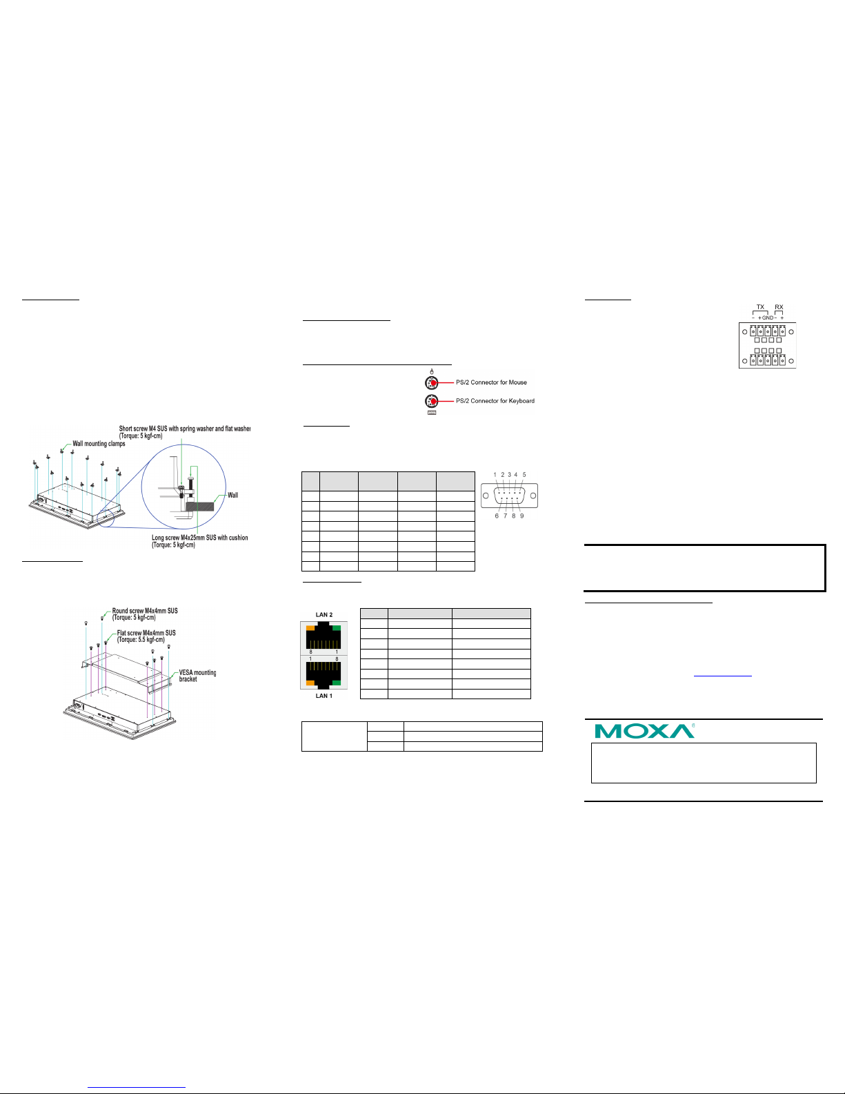
Wall Mounting
The MPC-2000 serie s comes with optional c lamp mounts for
installation onto a wall (where space has been cut out to
accommodate the rest of the hardware) or into computing stations
where a flush mount is desired.
For a secure mounting, use all 14 clamps on the MPC-2260 a nd
MPC-2240, or use 10 clamps on the MP C-2190.
The clamp arms are fastened into slots on a ll four sides of the
MPC-2000 series. Use the short M 4 SUS screw s to fasten the clamp
arms to the MPC -2000 series mounting slots, as shown in the
following figur e. Next, use the clamps to fasten the MPC-2000
series to its mounting point; note the torque value as shown in the
figure.
VESA Moun ting
The MPC-2000 series also comes with an optional VESA mounting
kit. Six flat screws and four round screws are required to attach the
VESA mounting bracket . See the following figure for detailed screw
specifications and torque values.
An additional fou r screws (not in cluded in the kit ) are required to
mount the MPC -2000 series on a VESA rack. For this purpose, use
M6 screws with a length between 10 and 12 mm.
Connector Description
Extendi ng the Display
The MPC-2000 serie s comes with both standard VGA (DB15) and
DVI-D (DB29) interfaces (on the bottom panel) that can be used to
simultaneously display across two monitors.
Connecting to a Keyboard and Mouse
The MPC-2000 serie s comes
with
two PS/2 connectors
located on the bottom
panel
for
connecting a keyboard and a
mouse.
Serial Ports
The MPC-2000 ser ies has two software- selectable
RS-232/422/485 DB9 serial ports. Re fer to the MPC-2000 Series
Hardware Manua l for informa tion on serial po rt configuration. The
pin assignments for the ports are shown in the following ta ble.
Pin RS-232 RS-422
RS-485
(4-wire)
RS-485
(2-wire)
1
DCD
TxDA(-)
TxDA(-)
–
2
RxD
TxDB(+)
TxDB(+)
–
3
TxD
RxDB(+)
RxDB(+)
DataB(+)
4
DTR
RxDA(-)
RxDA(-)
DataA(-)
5
GND
GND
GND
GND
6
DSR – –
–
7
RTS – –
–
8
CTS – –
–
Ethernet Ports
The pin assignments for t he two Gigabit Ether net 100/1000 Mbps
RJ45 ports are shown in the fol lowing table.
Pin
100 Mbps
1000 Mbps
1
ETx+
TRD(0)+
2
ETx-
TRD(0)-
3
ERx+
TRD(1)+
4 – TRD(2)+
5 – TRD(2)-
6
ERx-
TRD(1)- 7 –
TRD(3)+
8 – TRD(3)-
The following table describes the LAN LED indicators.
LAN
(on connectors)
Green
100 Mbps Ethernet mode
Yellow
1000 Mbps (Gigabit) Ethernet mode
Off
No activity or 10 Mbps Ethernet mode
NMEA Ports
The MPC-2000 serie s comes with
eight NMEA ports on the bottom
panel
. The figure shows the pin
assignments
.
Powering the MPC-2000 Series On or Off
To power on the MPC-2000 series, connect the Terminal Block to
Power Jack Converter to the MPC-2000 series DC terminal block
(located on the bottom panel) and then connect a power adapter;
or, alternately , you may power the device using the AC powe r
cord.
Touch the MENU button (in the lower right corner of the display
panel) for one second to turn on the computer. It takes about 10 to
30 seconds for the system to boot up.
To power off the MPC-2000 series, touch the MENU button for four
seconds; depending on the power management settings of the
operating system, you can select the “standby”, “hiberna tion”, or
“system shutdown” mode.
If you encounter any technical pro blems, touch the MENU button
for 10 secon ds to forc e the system to shut down.
NOTE If
the MPC-200 0 series is powe red using a DC converter ,
the system displays
Fail for the AC power status in the
INFO
dialog. This does not affect the operation of the
MPC-2000 series .
Grounding the MPC -2000 Series
Proper grounding and wire routing help to limit the effects of noise
from electromagnetic interference (EMI). Run the ground
connection from the ground screw to the grounding surface prior to
connecting the power source.
For detailed information on setup and config uration, refer to the
MPC-2000 Series Hardware Manual, which you can download from
the Moxa company website at www.moxa.com
.
 Loading...