

Page 1

P/N: 1802021500010
Technical Support Contact Information
www.moxa.com/support
Moxa Americas:
Toll
Tel:
Fax:
Moxa China (Shanghai office):
Toll
Tel:
Fax:
Moxa Europe:
Tel:
Fax:
Moxa Asia-Pacific:
Tel:
Fax:
Moxa India:
Tel:
Fax:
2015 Moxa Inc. All rights reserved.
MPC-2150 Series
Quick Installation Guide
Edition 1.0, October 2015
-free: 1-888-669-2872
1-714-528-6777
1-714-528-6778
+49-89-3 70 03 99-0
+49-89-3 70 03 99-99
+91-80-4172-9088
+91-80-4132-1045
-free: 800-820-5036
+86-21-5258-9955
+86-21-5258-5505
+886-2-8919-1230
+886-2-8919-1231
*1802021500010*
Page 2
Overview
The MPC-2150, 15-inch panel computer, with 3rd generation Intel®
Core™ processor delivers a reliable, durable, high-performance platform
of wide versatility of use in industrial environments.
The MPC-2150 series panel computers are designed with a wide -40 to
70°C temperature rang e, and co me w ith a patent ed fanless, streamlined
housing designed for highly efficient heat dissipation, making this
computer on e of most reliable industrial platforms available for harsh, hot,
outdoor environments, such as are found at oil and gas fields and on
drilling platforms.
The MPC-2150 also features a 1,000-nit LCD panel with a sunlight
readable and projected capacitive glove-friendly multi-touch screen,
providing an excellent user experience for outdoor applications.
Package Checklist
Before installing the MPC-2150, verify that the package contains the
following items:
• MPC-2150 panel computer
• 1 2-pin terminal block for DC power input
• SSD/HDD installation kit
• Documentation and driver DVD
• Quick installation guide (printed)
• Warranty card
NOTE: Please notify your sales representative if any of the above items
are missing or damaged.
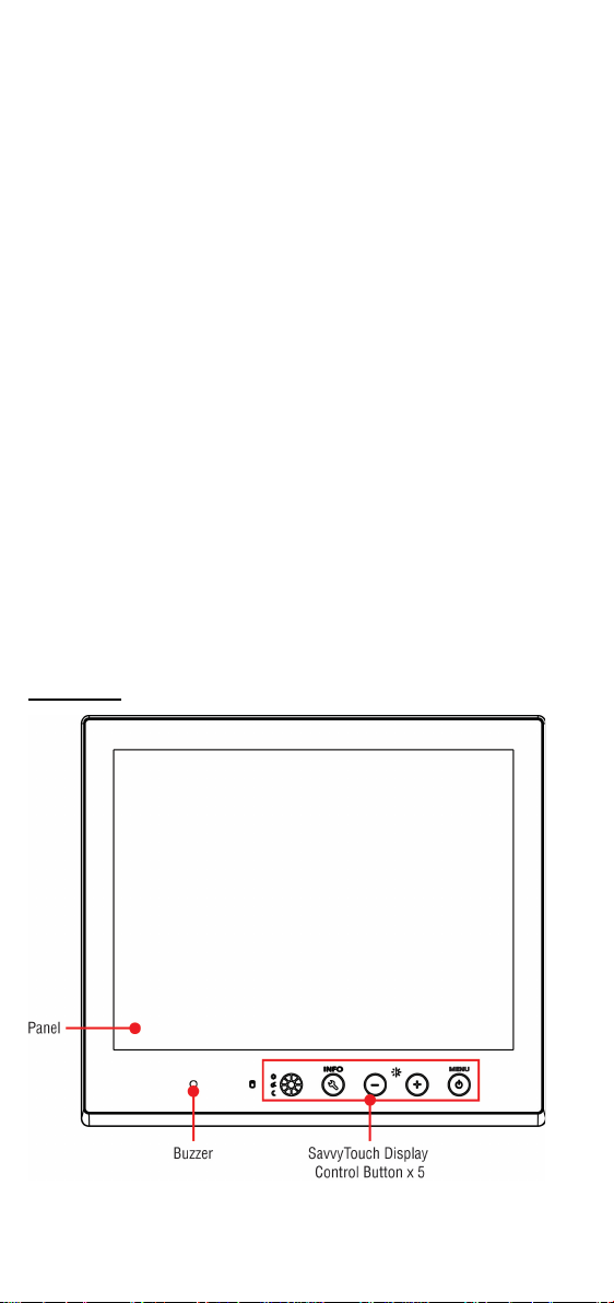
Hardware Installation
Front View
- 2 -
Page 3

Bottom View
Displayed
Color
Control Function /
Color Legend
Power is on and functioning
normally
Power standby and system shut
down
Off
Power is off.
+: To increase brightness of panel
Storage drive is functioning
properly
Red (blinking)
Drive is accessing or writing data
Off
Drive is offline.
Display
The MPC-2150 allows using either an AC or
DC power input. When using AC power, use
the standard C14 AC inlet. When using DC
power, use at least a 60 W power adapter
through the 2
accessories
MPC-2150’s DC pin assignments.
SavvyTouch Display Control Buttons
The following table describes the SavvyTouch display controls on the
front surface of th e MPC-2150. These intelligent controls will light up with
a simple hand-wave above the area of the s creen where they a re located.
Name
Green
Power
Red
Brightness White
Info
Storage
mode
Off System functioning normally
Red System hardware error
Red (on)
White Displays the brightness mode
Off
-: To decrease brightness of panel
Panel brightness out of ECDIS
standard range
Connector Description
AC/DC Power Input
-pin terminal block in the
package. The figure shows the
- 3 -
Page 4

Extending the Display
The
two
connectors located on the
bottom surface
keyboard and a mouse.
RS-485
(4-wire)
RS-485
(2-wire)
1
DCD
TxDA(-)
TxDA(-)
–
2
RxD
TxDB(+)
TxDB(+)
–
3
TxD
RxDB(+)
RxDB(+)
DataB(+)
4
DTR
RxDA(-)
RxDA(-)
DataA(-)
5
GND
GND
GND
GND 6 DSR – – – 7
RTS – – – 8
CTS – –
–
Pin
100 Mbps
1000 Mbps
1
ETx+
TRD(0)+
2
ETx-
TRD(0)-
3
ERx+
TRD(1)+
4 – TRD(2)+
5 – TRD(2)-
6
ERx-
TRD(1)-
7 – TRD(3)+
8 – TRD(3)-
Green
100 Mbps Ethernet mode
Yellow
1000 Mbps (Gigabit) Ethernet mode
Off
No activity / 10 Mbps Ethernet mode
The MPC-2150 comes with line-in
and line
users to connect a speaker
,
an earphone
The MPC-2150 comes w ith both st andard VGA (DB15) and DVI-D (DB29)
interfaces (located on the bottom of the shell) which may be used to
simultaneously extend the display across two monitors.
Connecting to a Keyboard and Mouse
MPC-2150 Series comes with
PS/2
, for connecting a
Serial Ports
The MPC-2150 offers two software-selectable RS-232/422/485 serial
ports over a DB9 connector. Refer to the MPC-2150 User’s Manual for
serial port configuration details. The pin assignments for the ports are
shown in the table below:
Pin RS-232 RS-422
Ethernet Ports
The pin assignments for the two Fast Ethernet 100/1000 Mbps RJ45 ports
are shown in the following table:
Refer to the following table for a description of the LAN indicators:
LAN
(on connectors)
Audio Interface
-out audio jacks, allowing
system
, or a microphone.
USB Ports
Four USB 2.0 ports are available on the bottom surface. Use these ports
to connect mass storage drives and other peripherals.
- 4 -
Page 5

Installing a SATA HDD or SSD
The MPC-2150 comes with an HDD/SSD installation kit accessory. To
install the 2.5-inch SATA storage, follow these instructions. For better
system reliability, we suggest using a solid state disk (SSD). A list of
compatible SSD models is available on Moxa’s website.
1. Use 4 screws to fasten the HDD/SSD to the HDD/SSD bracket.
2. Remove the 2 screws holding the HDD/SSD cover to the MPC-2150.
3. Insert the HDD/SSD (with the bracket) into the HDD/SDD slot. Noted
that the latch on HDD/SSD bracket should be released when pushing
the HDD/SSD into the slot.
4. Reattach the HDD/SSD cover and fix it to the front panel with the 2
screws.
Installing a CFast Card
The MPC-2150 has a CFast slot that can be used to install a standard
CFast card using a push-push mechanism. A list of compatible CFast cards
can be found on Moxa’s website.
- 5 -
Page 6

1. Loosen the screws connecting the HDD/SSD cover to the MPC-2150.
ATTENTION
There is a risk of explosion if the
replaced with an incompatible battery.
2. Insert the CFast card into the slot using the push-push mechanism.
3. Reattach the CFast cover.
Real Time Clock
The real time clock (RTC) is powered by a lithium battery. We strongly
recommend that you do not replace the lithium battery without help f rom
a qualified Moxa support engineer. If you need to change the battery,
contact the Moxa RMA service team at
http://www.moxa.com/rma/about_rma.aspx
.
clock’s lithium battery is
Powering on/off the MPC-2150
To power on the panel computer you may either connect power by
connecting the Terminal Block to Power Jack Converter to the
terminal block and then connect a power adapter, or you may connect the
computer to an AC power source using the power cord. After the power
source is connected, touch the Menu button to turn the computer on. It
takes about 10 to 30 seconds for the system to boot up.
To power off the MPC-2150 Series, touch the MENU button for 4 seconds ;
depending on your OS’s power management settings you may enter
standby, hibernation, or system shutdown mode. If you encounter
technical problems, touch and hold the MENU button for 10 seconds to
force a hard shutdown of the system.
Grounding the MPC-2150 Series
Proper grounding and wire routing help to limit the effects of noise from
electromagnetic interference (EMI). Run the ground connect ion from the
ground screw to the grounding surface prior to connecting the power
source.
- 6 -
 Loading...