

Page 1

– 1 – – 2 – – 3 –
P/N: 1802001220010
MPC-122-K
Quick Installation Guide
First Edition, December 2010
1. Overview
The MPC-122-K marine panel computers feature a 2.26 GHz Intel
Core 2 Duo processor with up to 4 GB of system memory, providing
high performance for system operation. The MPC-122-K
computers have 2 RS-232/422/485 serial ports for reliable serial
communications, and 2 Gigabit LAN ports for high speed Ethernet
transmission and network redundancy. Features easily accessed
from the computer’s panel include full range dimming, optical
bonding, wide viewing angle, and color calibration.
2. Package Checklist
Before installing the MPC-122-K, verify that the package contains
the following items:
• 1 MPC-122-K panel computer
• PS/2 to KB/MS Y-type cable
• 2 sets of hard disk drive cables and 1 set of SATA disk power
cables
• Rubber water proofing cushion
• Hard disk drive ground sticker
• Documentation and software CD
• Quick installation guide (printed)
• Warranty card
Note: Please notify your sales representative if any of the above
items are missing or damaged.
3. MPC-122-K Panel Layout
UBottom View
Computer
Panel
USide and Front Views
Panel
Menu Botton
USB Port with
Water-proof Cover
Adjustment Button
Computer Panel
UComputer
Power Input
CompactFlash
Card Socket
Power Switch
PS/2
Audio Output/Input
Gigabit Ethernet
Port x 2
USB 2.0
Host x 6
DVI-D/VGA Output
Serial Port x 2
(RS-232/422/485)
Antenna Hole
(reserved)
LED Indicators
(Storage, Power)
ULED Indicators
The following table describes the LED indicators located on the
front panel of the MPC-122-K.
LED Name LED Color LED Function
Green Power is on and functioning normally
Power
Off Power is off or power error exists
Yellow (on) CF card is inserted and detected
Yellow
(blinking)
Data is being read from or written to
the CF card or HDD
Storage
Off No activity
Green 100 Mbps Ethernet mode
Yellow 1000 Mbps (Gigabit) Ethernet mode
LAN
Off No activity or 10 Mbps Ethernet mode
4. Installing the MPC-122-K
UWall or Cabinet Mounting
There are four screw holes on each side of the panel. Place the
rubber water proofing cushion on the back of the panel, and then
use two screws per side to attach the MPC-122-K to a wall or
cabinet.
Screws
Screws
5. Panel Adjustment
There are two buttons located in the right bottom corner of the
panel. Click the Menu Button to access panel adjustment items,
and then use the arrows or the Adjustment Button for each
configuration. Select Exit or push the button to close the
configuration menu.
6. Connector Description
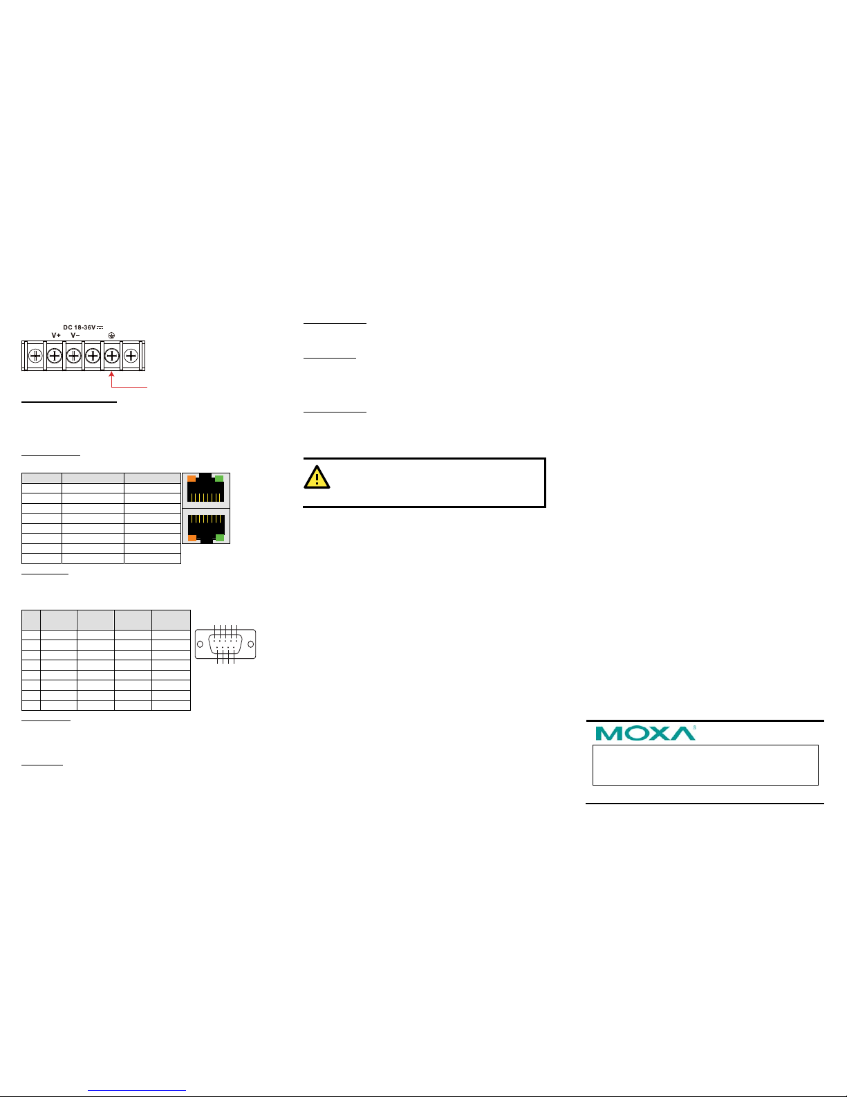
UPower Connector
The MPC-122-K has an 18 to 36 VDC power input located on the
terminal block. The Power LED will light up when power is being
properly supplied. When The Ready LED lights to a solid green, the
OS is ready. When the Ready LED lights to a solid green, the OS is
ready
UGrounding the MPC-122-K
Grounding and write routing help limit the effects of noise due to
electromagnetic interference (EMI). Run the ground connection
from the ground screw to the grounding surface prior to connecting
the power.
ATTENTION
This product is intended to be mounted to a well-grounded
mounting surface, such as a metal panel.
Page 2
– 4 – – 5 – – 6 –
www.moxa.com/support
The Americas: +1-714-528-6777 (toll-free: 1-888-669-2872)
Europe: +49-89-3 70 03 99-0
Asia-Pacific: +886-2-8919-1230
China: +86-21-5258-9955 (toll-free: 800-820-5036)
2010 Moxa Inc., All Rights Reserved
Earth Ground: Refer to the following figure for the location of the
Earth Ground on the terminal block power connector. Connect the
EG wire to an appropriate grounded metal surface.
EG
UVGA and DVI-D Outputs
The MPC-122-K comes with a D-Sub 15-pin female connector on
the front panel to connect a VGA CRT monitor. It also comes with
a DVI-D connector on the front panel to connect to a panel with
HDMI (High-Definition Multimedia Interface).
UEthernet Ports
The 10/100/1000 Mbps Ethernet ports use RJ45 connectors.
Pin 10/100 Mbps 1000 Mbps
1 ETx+ TRD(0)+
2 ETx- TRD(0)3 ERx+ TRD(1)+
4 – TRD(2)+
5 – TRD(2)6 ERx- TRD(1)7 – TRD(3)+
8 – TRD(3)-
18
8
1
USerial Ports
The serial ports use DB9 connectors. Each port can be configured
by software for RS-232, RS-422, or RS-485. The pin assignments
for the ports are shown in the following table:
Pin RS-232 RS-422 RS-485
4-wire
RS-485
2-wire
1 DCD TxDA(-) TxDA(-) –
2 RxD TxDB(+) TxDB(+) –
3 TxD RxDB(+) RxDB(+) DataB(+)
4 DTR RxDA(-) RxDA(-) DataA(-)
5 GND GND GND GND
6 DSR – – –
7 RTS – – –
8 CTS – – –
12345
6789
UCF Card Slot
The MPC-122-K computer comes with a CompactFlash socket
located on the front panel. Remove the protective cap on the front
panel to install the CompactFlash card.
UUSB Hosts
The MPC-122-K has six USB 2.0 full speed hosts that use a type A
connector on the front panel of the computer. An additional USB
port is located on the display. The port supports a keyboard and
mouse, and can also be used to connect a Flash disk for storing
large amounts of data.
UAudio Interface
The MPC-122-K comes with an audio input and an audio output,
allowing users to connect a speaker or an earphone.
UReset Button
Press the “Reset Button” on the front panel of the MPC-122-K to
reboot the system. The Ready LED will blink on and off for the first
5 seconds, and then maintain a steady glow once the system has
rebooted.
UReal-time Clock
The MPC-122-K's real-time clock is powered by a lithium battery.
You should not replace the lithium battery without help from a
qualified Moxa support engineer. If you need to change the battery,
contact the Moxa RMA service team.
ATTENTION
T
here is a risk of explosion if the battery is replaced with an
incorrect type of battery.
7. Powering on the MPC-122-K
To power on the MPC-122-K, connect the “terminal block to power
jack converter” to the MPC-122-K’s DC terminal block (located on
the side panel), and then connect the power adaptor. Press the
Power Switch button to turn on the computer. Note that the Earth
Ground wire should be connected to the top pin of the terminal
block. It takes about 30 seconds for the system to boot up. Once
the system is ready, the Power LED will light up.
 Loading...