

Page 1
– 1 – – 2 – – 3 –
P/N: 1802036600010
*1802036600010*
MGate MB3660 Series
Quick Installation Guide
First Edition, August 2015
Overview
The MGate MB3660 (MB3660-8 and MB3660-16) series gateways
are 8 and 16-port redundant Modbus gateways that convert
between the Modbus TCP and Modbus RTU/ASCII protocols. The
gateways come with built-in dual AC or DC power inputs for power
redundancy, and have dual Ethernet ports (with different IPs) for
network redundancy. The dual Ethernet ports can use the same IP
address for cable redundancy.
The MGate MB3660 series gateways provide not only
serial-to-Ethernet communication, but also
serial(Master)-to-serial(Slave) communication, and can be
accessed by up to 256 TCP master/client devices, or connected to
128 TCP slave/server devices.
Each serial port can be configured individually for Modbus RTU or
Modbus ASCII operation and for different baudrates, allowing both
types of networks to be integrated with Modbus TCP through one
Modbus gateway.
Package Checklist
Before installing the MGate MB3660 series gateway, verify that the
package contains the following items:
• 1 MGate MB3660-8 or MB3660-16 gateway
• 1 RJ45-to-DB9 female serial cable for console setting
• 2 L-shaped brackets for wall mounting
• 2 AC power cords (for AC models)
• Documentation and software CD
• Quick installation guide
• Product warranty statement
Optional Accessories
• Mini DB9F-to-TB Adapter: DB9 female to terminal block
adapter for RS-422/485 applications
• CBL-RJ45M9-150: 8-pin RJ45 to DB9 male cable, 150 cm
• CBL-RJ45F9-150: 8-pin RJ45 to DB9 female cable, 150 cm
Notify your sales representative if any of the above items are
missing or damaged.
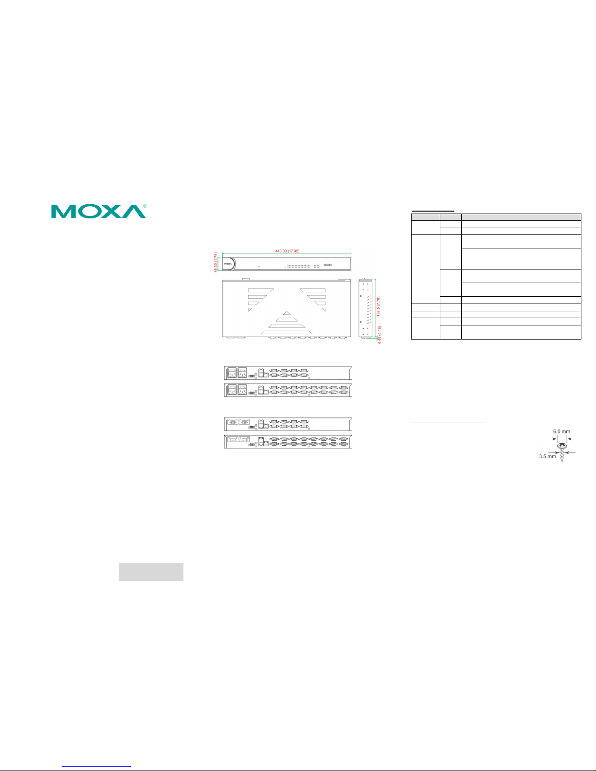
Hardware Introduction
As shown in the following figures, the MGate MB3660-8 has 8 DB9
ports for transmitting serial data, and the MGate MB3660-16 has
16 DB9 ports for transmitting serial data. The MGate MB3660I
series gateways provide 2 kV serial port isolation protection.
AC Models
DC Models
Reset Button— Press the Reset button continuously for 5 sec to
load factory defaults
The reset button is used to load factory defaults. Hold the reset
button down for five seconds using a pointed object such as a
straightened paper clip. Release the reset button when the Ready
LED stops blinking.
LED Indicators
Name
Color
Function
PWR 1,
PWR 2
Red
Power is being supplied to the power input
Off
Power cable is not connected
Ready
Red
Steady on: Power is on and the unit is booting
up
Blinking: IP conflict, DHCP, or BOOTP server
did not respond properly, or a relay output
occurred
Green
Steady on: Power is on and unit is functioning
normally
Blinking: Unit is responding to the locate
function
Off
Power is off, or power error condition exists
Tx (1-16)
Green
Serial port is transmitting data
Rx (1-16)
Amber
Serial port is receiving data
LAN 1,
LAN 2
Green
Indicates 100 Mbps Ethernet connection
Amber
Indicates 10 Mbps Ethernet connection
Off
Ethernet cable is disconnected
Hardware Installation Procedure
STEP 1:
After unpacking the unit, connect the power supply to the
unit. STEP 2:
Use an Ethernet cable to connect the unit to the network.
STEP 3:
Connect your device to the desired port on the unit.
STEP 4:
Place or mount the unit. The unit may be placed on a
horizontal surface such as a desktop, or mounted on the
wall.
Wall or Cabinet Mounting
Two metal plates are provided for mounting the
unit on a wall or inside a cabinet. Attach the
plates to the unit’s rear panel with screws. With
the plates attached, use screws to mount the unit
on a wall.
For each screw, th
e head should be 6.0 mm or
less in diameter, and the shaft should be 3.5 mm
or less in diameter.
Page 2

– 4 – – 5 – – 6 –
www.moxa.com/support
The Americas:
+1-714-528-6777 (toll-free: 1-888-669-2872)
Europe:
+49-89-3 70 03 99-0
Asia-Pacific:
+886-2-8919-1230
China:
+86-21-5258-9955 (toll-free: 800-820-5036)
2015 Moxa Inc. All rights reserved.
Termination Resistor and Adjustable Pull High/Low
Resistors
In some critical environments, you may need to add termination
resistors to prevent the reflection of serial signals. When using
termination resistors, it is important to set the pull high/low
resistors correctly so that the electrical signal is not corrupted. The
MGate MB3660 uses DIP switches to set the pull high/low resistor
values for each serial port. To expose the DIP switches located on
the back of the PCB, first remove the screws holding the DIP switch
cover in place, and then remove the cover. The sequence from
right to left is port 1 to port 16.
To add a 120 Ω termination resistor, set switch 3 on the port's
assigned DIP switch to ON; set switch 3 to OFF (the default setting)
to disable the termination resistor.
To set the pull high/low resistors to 150 KΩ, set switches 1
and 2 on the port's assigned DIP switch to OFF. This is the default
setting.
To set the pull high/low resistors to 1 KΩ, set switches 1 and
2 on the port's assigned DIP switch to ON.
Pull High/low Resistors for the RS-485 Port
Default
SW
1 2 3
Pull High
Pull Low
Terminator
ON
1 KΩ
1 KΩ
120 Ω
OFF
150 KΩ
150 KΩ
---
Software Installation Information
To configure your MGate MB3660, connect the gateway ’s Ethernet
port directly to your computer’s Ethernet port and then log in from
a web browser. The default IP addresses of LAN1 and LAN2 are
192.168.127.254 and 192.168.126.254, respectively. The MG at e
supports two types of accounts: admin and user. The admin
account can modify all settings, whereas the user account can
only view settings. The default password for the admin account is
“moxa”.
If you forget the modified IP address of the gateway or cannot log
in to the gateway via a web browser for any r eason, you can access
the gateway via a direct Ethernet cable connection using the
Device search utility to search for the gateway.
To install Device Search Utility (DSU), insert the MGate
Documentation and Software CD into your PC’s CD-ROM drive,
and then run the following setup program to begin the installation
process from the “Software” directory:
dsu_setup_[Version]_Build_[DateTime].exe
The filename of the latest version may have the following format:
dsu_setup_Verx.x.x_Build_xxxxxxxx.exe.
For detailed information about DSU, refer to the MGate MB3660
User's Manual, which can be found in the “Document” directory.
Pin Assignments
RJ45 (LAN, Console)
Pin LAN
Console
(RS-232)
1
Tx+
DSR 2 Tx-
RTS
3
Rx+
GND
4 – TxD 5 –
RxD
6
Rx-
DCD
7 – CTS 8 –
DTR
DB9 Male (RS-232/422/485)
Pin RS-232
RS-422/
RS-485-4W
RS-485-2W
1
DCD
TxD-(A)
–
2
RxD
TxD+(B)
– 3 TxD
RxD+(B)
Data+(B)
4
DTR
RxD-(A)
Data-(A)
5
GND
GND
GND 6 DSR – –
7
RTS – –
8
CTS – – 9 – – –
Relay Output
N.O. Common N.C.
Specifications
Power Input
Dual 20 to 60 VDC (for DC models);
or dual 100 to 240 VAC,
47 to 63 Hz (for AC models)
Power Consumption
MGate MB3660-8-2AC
MGate MB3660-8-2DC
MGate MB3660I-8-2AC
MGate MB3660-16-2AC
MGate MB3660-16-2DC
144mA/110V, 101mA/220V
312mA/24V, 156mA/48V
244mA/110V, 159mA/220V
178mA/110V,120mA/220V
390mA/24V, 195mA/48V
Operating Temperature
0 to 60°C (32 to 140°F)
Storage Temperature
-40 to 85°C (-40 to 185°F)
Operating Humidity
5 to 95% RH
Dimensions (W x D x H)
440 x 197.5 x 45.5 mm
(17.32 x 7.78 x 1.79 in)
Magnetic Isolation
1.5 kV for Ethernet,
2 kV for serial port (for I models)
Regulatory Approvals
FCC Class A, CE Class A, UL 60950-1
Fault Relay Circuit
3-pin circuit with current carrying
capacity of 2 A @ 30 VDC
 Loading...