

Page 1
– 1 – – 2 – – 3 –
P/N: 1802034800013
MGate MB3480
Quick Installation Guide
Fifth Edition, February 2014
Overview
The MGate MB3480 is a 4-port Modbus gateway that converts
between Modbus TCP and Modbus RTU/ASCII protocols. It can be
used to allow Ethernet masters to control serial slaves, or to allow
serial masters to control Ethernet slaves. Up to 16 TCP masters
and 124 serial slaves can be connected simultaneously.
Package Checklist
Before installing the MGate MB3480 Modbus gateway, verify that
the package contains the following items:
• 1 MGate MB3480 Modbus gateway
• Document & Software CD
• Quick Installat ion Guide
• Product Warranty Statement
Optional Accessories
• DK-35A: DIN-rail mounting kit ( 35 mm)
Notify your sales representative if any of the above items is
missing or damaged.
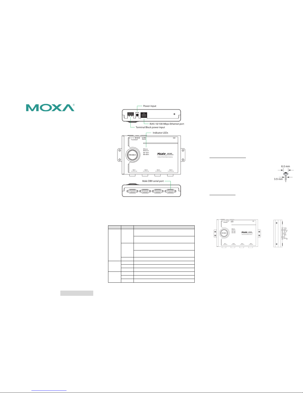
Hardware Introduction
As shown in the following figures, the MGate MB3480 has 4 DB9
male ports for transmitting serial data.
Reset Button—The reset button is used to load factory defaults.
Hold the reset button down for five seconds using a pointed object
such as a straightened paper clip. Release the reset button when
the Ready LED stops blinking.
LED Indicators—Six LED indicators are loc ated on the top pan el:
Name
Color
Function
Ready
Red
On:
Power is on and the unit is booting
up.
Blinking: IP conflict exists, or
DHCP or BOOTP
server did not respond properly.
Green
On:
Power is on and the unit is
functioning normally.
Blinking: Un it has found by the Location
command in MGate Manager.
Off
Power is off or power error condition exists
Link
Orange
10 Mbps Ethernet connection
Green
100 Mbps Ethernet connection
Off
Ethernet cable is disconnected or has a short
P1, P2,
P3, P4
Orange
Unit is receivin g data from dev ice
Green
Unit is transmitt ing data to de vice
Off
No data is bein g exchanged with device
Hardware Installation Procedure
STEP 1: After unpacking the
unit, connect the power supply or
power adaptor to the unit.
STEP 2: Use a standard straight
-through Ethernet cable to
connect the
unit to a network hub or switch. Use a
cross
-over Ethernet cable if you are connecting the
gateway directly to a PC
.
STEP 3: Connect your device to the desired port on the
unit.
STEP 4:
Place or mount the unit. The unit may be placed on a
horizontal surface such as a desktop, mounted on a
DIN-rail, or mounte d on the wall.
Wall or Cabinet Mounting
T
wo metal plates are provided
for mounting the
unit on a wall or inside a cabinet. Attach the
plates to the unit’s rear panel with screws. With
the plates attached, use screws to mount the unit
on a wall.
For each screw, the head should be 6.0 mm or
less in diameter , and the shaft shou ld be 3.5 mm
or less in diame ter.
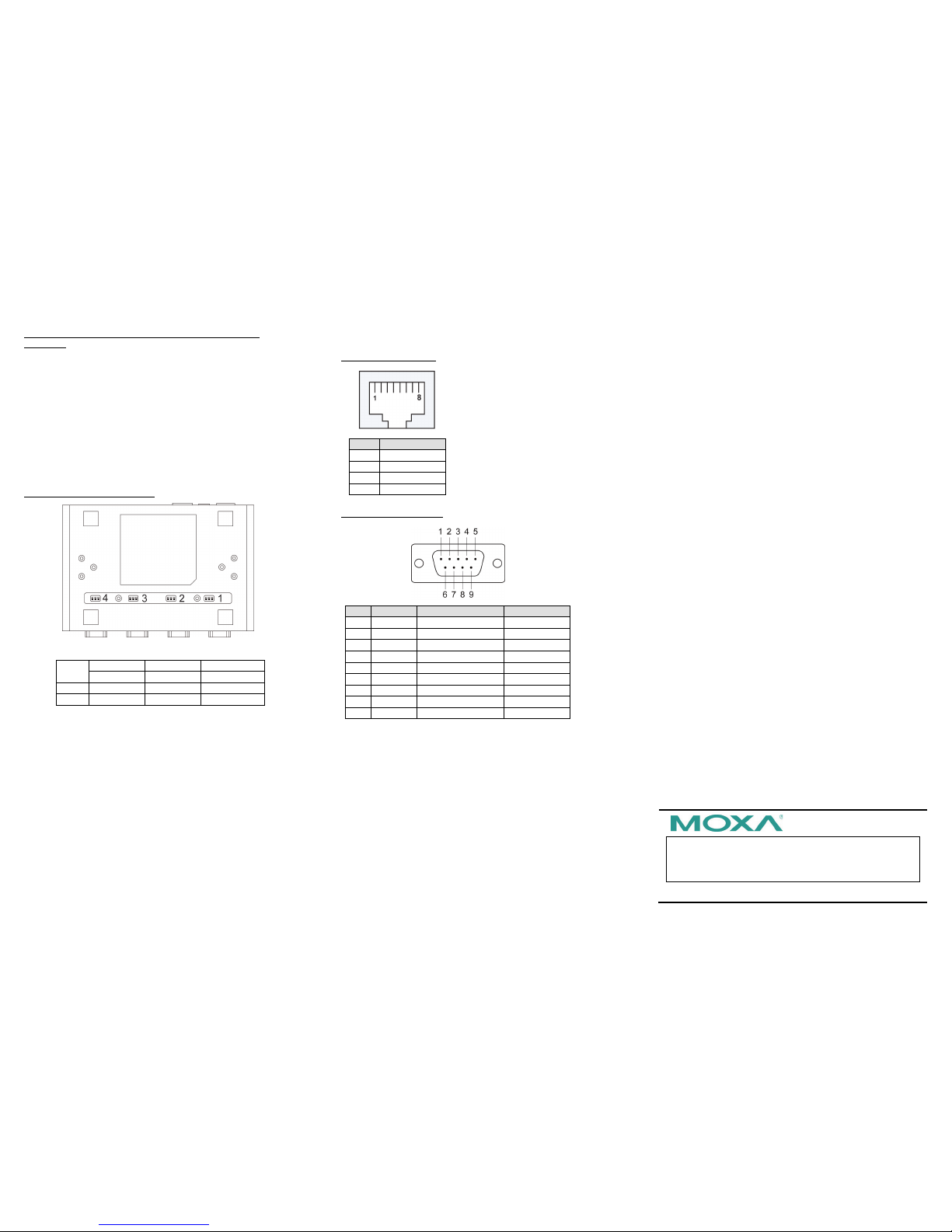
DIN-rail Mounting
DIN-rail attachments can be purchased separately to mount the
MGate MB3480 on a DIN-rail. When mounting the unit on a
DIN-rail, make s ure that it is orie nted with the me tal springs on
top.
Wall Mounting
DIN-rail Mounting
Page 2
– 4 – – 5 – – 6 –
www.moxa.com/support
The Americas:
+1-714-528-6777 (toll-free: 1-888-669-2872)
Europe:
+49-89-3 70 03 99-0
Asia-Pacific:
+886-2-8919-1230
China:
+86-21-5258-9955 (toll-free: 800-820-5036)
2014 Moxa Inc. All r ights reserved.
Termination Resistor and Adjustable Pull High/Low
Resistors
For some RS-485 environments, you may need to add termination
resistors to prevent the reflection of serial signals. When using
termination res istors, it is impo rtant to set the pull high/low
resistors correctly so that the electrical signal is not corrupted. For
each serial port, DIP switches are used for termination resistor and
pull high/low resistor sett ings. To ena ble the 120 Ω termination
resistor, set switch 3 on the assigned DIP switch to ON; set it to
OFF (the default setting) to disable the termination resistor. To set
the pull high/low resistors to 150 KΩ (the default setting), set
switches 1 and 2 on the assigned DIP switch to the OFF position;
set them both to ON for 1 KΩ.
MGate MB3480 DIP Switches
Pull High/low Resistors for the RS-485 Port
SW
1 2 3 Pull High
Pull Low
Terminator
ON
1KΩ
1KΩ
120Ω
Default
OFF
150KΩ
150KΩ
---
Software Installation Information
To install MGate Manager, insert the MGate Doc ument &
Software CD into your PC’s CD-ROM drive. Locatje and run the
setup program, wihich will be named
MGM_Setup_[Version]_Build_[DateTim e].exe (e.g.,
MGM_Setup_Ver1.1.0_Build_07041910.exe) and follow the
on-screen instructions.
For more information about MGate Manager, please refer to the
MGate MB3000 U ser’s Manual.
Pin Assignments
Ethernet Port (RJ45)
Pin
Signals
1
Tx+
2
Tx- 3 Rx+
6
Rx-
Serial Port (Male DB9)
Pin
RS-232
RS-422/485 (4W)
RS-485 (2W)
1
DCD
TxD-(A)
--- 2 RxD
TxD+(B)
---
3
TxD
RxD+(B)
Data+(B)
4
DTR
RxD-(A)
Data-(A)
5
GND
GND
GND 6 DSR
---
--- 7 RTS
---
--- 8 CTS
---
--- 9 ---
---
---
Environmental Specifications
Power Requirements
Power Input
12 to 48 VDC
Power Consumption
385 mA@12 VDC, 110 mA@48 VDC
Operating Temperature
0 to 55°C (32 to 131°F)
Operating Humidity
5 to 95% RH
Dimensions (W x D x H )
158 x 33 x 103 mm
6.22 x 1.3 x 40.6 in
Surge Protection
15 KV ESD for seria l port
Magnetic Isola tion
15 KV for Ethernet
Power Line Protection
4 KV burst (EFT), EN61000-4-4
2 KV surge, EN61000-4-5
Regulatory Approvals
FCC Class A, CE Class A, UL, CUL, TUV
 Loading...