

Moxa Technologies MGate MB3170, MGate MB3270, MGate MB3170I, MGate MB3270I Quick Installation Manual
Page 1

P/N: 1802031700014
*1802031700014*
MGate MB3170/MB3270
Quick Installation Guide
Edition 7.1, February 2016
Technical Support Contact Information
www.moxa.com/support
Moxa Americas:
Toll
-free: 1-888-669-2872
Tel:
1-714-528-6777
Fax:
1-714-528-6778
Moxa China (Shanghai office):
Toll
-free: 800-820-5036
Tel:
+86-21-5258-9955
Fax:
+86-21-5258-5505
Moxa Europe:
Tel:
+49-89-3 70 03 99-0
Fax:
+49-89-3 70 03 99-99
Moxa Asia-Pacific:
Tel:
+886-2-8919-1230
Fax:
+886-2-8919-1231
Moxa India:
Tel:
+91-80-4172-9088
Fax:
+91-80-4132-1045
2016 Moxa Inc. All rights reserved.
Page 2
- 2 -
Overview
The MGate MB3170 and MB3270 are 1 and 2-port advanced Modbus
gateways that convert between Modbus TCP an d Modbus ASCII/RTU
protocols. They can be used to allow Ethernet masters to control serial
slaves, or to allow serial masters to con trol Ethernet slaves. Up t o 32 TCP
masters and 31 serial slaves can be connected simultaneously.
Package Checklist
Before installing the MGate MB3170 or MB3270, verify that the package
contains the following items:
• MGate MB3170 or MB3270 Modbus gateway
• Document & Software CD
• Quick Installation Guide
• Product Warranty Statement
Optional Accessories:
• DK-35A: DIN-rail mounting kit (35 mm)
• Mini DB9F-to-TB Adaptor: DB9 female to terminal block adapter
• DR-4524: 45W/2A DIN-rail 24 VDC power supply with universal 85
to 264 VAC input
• DR-75-24: 75W/3.2A DIN-rail 24 VDC power supply with universal
85 to 264 VAC input
• DR-120-24: 120W/5A DIN-rail 24 VDC power supply with 88 to 132
VAC/176 to 264 VAC input by switch
Please notify your sales representative if any of the above items is
missing or damaged.
Hardware Introduction
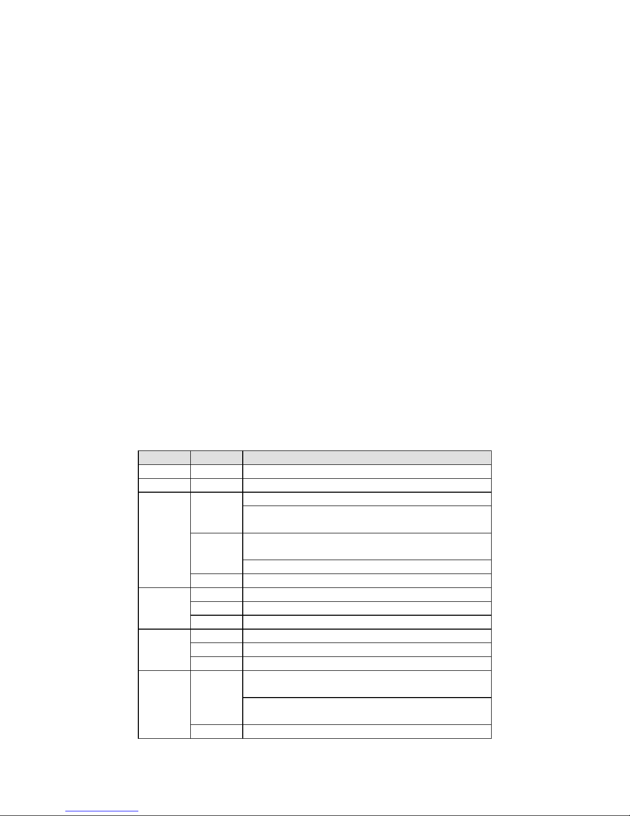
LED Indicators
Name
Color
Function
PWR1
Red
Power is being supplied to the power input
PWR2
Red
Power is being supplied to the power input
RDY
Red
Steady: Power is on and the unit is booting up
Blinking: IP conflict, DHCP or BOOTP server did not
respond properly, or a relay output occurred
Green
Steady: Power is on and the unit is functioning
normally
Blinking: Unit is responding to locate function
Off
Power is off or power error condition exists
Ethernet
Amber
10 Mbps Ethernet connection
Green
100 Mbps Ethernet connection
Off
Ethernet cable is disconnected or has a short
P1, P2
Amber
Serial port is receiving data
Green
Serial port is transmitting data
Off
Serial port is not transmitting or receiving data
FX
Amber
Steady on: Ethernet fiber connection, but port is
idle.
Blinking: Fiber port is transmitting or receiving
data.
Off
Fiber port is not transmitting or receiving data.
Page 3

- 3 -
Reset Button
Press the Reset button continuously for 5 sec to load factory defaults:
The reset button is used to load factory defaults. Use a pointed object
such as a straightened paper clip to hold the reset button down for five
seconds. Release the reset button when the Ready LED stops blinking.
Panel Layouts
The MGate MB3170 has a male DB9 port and a terminal block for
connecting to serial devices. The MGate MB32 70 has two DB9 connectors
for connecting to serial devices.
Page 4

- 4 -
Hardware Installation Procedure
STEP 1:
Use a standard straight
-through Ethernet (fiber) cable to
connect the unit to a network hub or switch.
STEP 2:
Connect your device to the unit's serial port.
STEP 3:
Mount the unit on a DIN-rail.
STEP 4:
Connect the power source to power input.
Software Installation Information
To install MGate Manager, insert the MGate Documenta tion and Software
CD into your PC's CD-ROM drive, and then run the following setup
program to begin the installation process from t h e "Software" directory:
MGM_Setup_[Version]_Build_[DateTime].exe
The filename of the latest version may have the following format:
MGM_Setup_Verx.x.x_Build_xxxxxxxx.exe.
For detailed information about MGate Manager, refer to the MGate
MB3000 User's Manual, which can be found in t he "Document" d irectory.
Pin Assignments
Ethernet Port (RJ45)
Pin
Signal
1
Tx+
2
Tx-
3
Rx+
6
Rx-
Serial Port (DB9 Male*)
*Note: For the MB3170
series, the DB9 male
port
can only be used
for RS
-232.
Pin RS-232
RS-422/
RS-485 (4W)
RS-485 (2W)
1
DCD
TxD-
–
2
RxD
TxD+
–
3
TxD
RxD+
Data+
4
DTR
RxD-
Data-
5
GND
GND
GND
6
DSR – –
7
RTS – –
8
CTS – –
9 – –
–
Serial Port (Terminal Block)
Pin
RS-422/
RS-485 (4W)
RS-485 (2W)
1
TxD+
– 2 TxD-
– 3 RxD+
Data+
4
RxD-
Data-
5
GND
GND
Page 5

- 5 -
Power Input and Relay Output Pinouts
V2+ V2-
V1+ V1-
Shielded
Ground
DC
Power
Input 1
DC
Power
Input 1
N.O. Common N.C.
DC
Power
Input 2
DC
Power
Input 2
Optical Fiber Interface
100BaseFX
Multi-mode
Single-mode
Fiber Cable Type OM1
50/125 μm
G.652
800 MHz*km
Typical Distance
4 km
5 km
40 km
Wavelength
Typical (nm)
1300
1310
TX Range (nm)
1260 to 1360
1280 to 1340
RX Range (nm)
1100 to 1600
1100 to 1600
Optical
Power
TX Range (dBm)
-10 to -20
0 to -5
RX Range (dBm)
-3 to -32
-3 to -34
Link Budget (dB)
12
29
Dispersion Penalty (dB)
3
1
Note: When connecting a single-mode fiber transceiver, we recommend
using an attenuator to prevent damage caused by excessive optical
power.
Note: Compute the “typical distance” of a specific fiber transceiver as
follows: Link budget (dB) > dispersion penalty (dB) + total link loss (dB).
Specifications
Power Requirements
Power Input
12 to 48 VDC
Power Consumption
MB3170:
MB3170I:
MB3270:
MB3270I:
435 mA @ 12 V, 218 mA @ 24 V,
109 mA @ 48 V
555 mA @ 12 V, 278 mA @ 24 V,
138 mA @ 48 V
435 mA @ 12 V, 218 mA @ 24 V,
109 mA @ 48 V
510 mA @ 12 V, 255 mA @ 24 V,
128 mA @ 48 V
Operating Temperature
0 to 60°C (32 to 140°F),
-40 to 75°C (-40 to 167°F) for –T model
Storage Temperature
-40 to 85°C (-40 to 185°F)
Operating Humidity
5 to 95% RH
Magnetic Isolation
Protection (serial)
2 kV (for “I” models)
Dimensions
Without ears:
With ears extended:
29 x 89.2 x 118.5 mm
(1.14 x 3.51 x 4.67 in)
29 x 89.2 x 124.5 mm
(1.14 x 3.51 x 4.90 in)
Page 6

- 6 -
Relay Output
1 digital relay out put to alarm (normal
close
): current carrying capacity 1 A @ 30
VDC
Hazardous Location
UL/cUL Class 1 Division 2 Group A/B/C/D,
ATEX Zone 2, IECEx
This device complies with Part 15 of the FCC rules.
Operation is subject to the following conditions:
1. This device may not cause harmful interference.
2. This device must accept any interference received, including
interference that may cause undesired operation.
ATEX and IECEx Information
1.
DEMKO Certification number: 07 ATEX 0690059X IEC Certification
Number: IECEx UL 13.0023X (only for models with suffix –CT or –
IEX)
2. Ambient Temperature Range (-40°C ≤ Tamb ≤ 75°C)
3.
Certification String: Ex nA IIC T3 Gc
4.
Standards Covered: EN 60079-0:2012/IEC 60079-
0 6th Ed. AND E N
60079-15:2010/IEC 60079-15 4th Ed.
5.
The conditions of safe usage:
•
The Ethernet Communications Devices are intended for mounting
in a tool-accessible IP54 enclosure and used in an area of not
more than pollution degree 2 as defined by IEC 60664-1.
• Conductors suitable for use in an ambient temperature greater
than 114°C must be used for the power supply terminal.
• A 4mm2 conductor must be used when connection to
the external
grounding screw is utilized.
•
Provisions shall be made, either in the equipment or external to
the equipment, t o prevent the pea k rated voltage bei ng exceeded
by the transient disturbances of more than 140%.
 Loading...