

Moxa Technologies MGate MB3000, MGate MB3170, MGate MB3180, MGate MB3280, MGate MB3480 User Manual
...Page 1

MGate MB3000 Modbus G ateway
User Manual
Sixth Edition, July 2012
www.moxa.com/product
2012 Moxa Inc. All rights reserved.
Page 2

MGate MB3000 Modbus G ateway
User’s Manual
The software described in this manual is furnished under a license agreement and may be used only in accordance
with the terms of that agreement.
Copyright Notice
Copyright 2012 Moxa Inc.
All rights reserved.
Reproduction without permission is prohibited.
Trademarks
MOXA is a registered trademark of Moxa Inc.
All other trademarks or registered marks in this manual belong to their respective manufacturers.
Disclaimer
Information in th is doc um e nt is subject to ch ange without notice an d does not represent a commitment on the part
of Moxa.
Moxa provides this document “as is,” without warranty of any kind, either expressed or implied, including, but not
limited to, its particular purpose. Moxa reserves the right to make improvements and/or changes to this manual, or
to the products and/or the programs described in this manual, at any time.
Information provided in this manual is intended to be accurate and reliable. However, Moxa assumes no
responsibility for its use, or for any infringements on the rights of third parties that may result from its use.
This product might include unintentional technical or typographical err ors. Changes are periodically made to the
information herein to correct such errors, and these changes are incorporated into new editions of the publication.
Technical Support Contact Information
www.moxa.com/support
Moxa Americas:
Toll-free: 1-888-669-2872
Tel: +1-714-528-6777
Fax: +1-714-528-6778
Moxa China (Shanghai office):
Toll-free: 800-820-5036
Tel: +86-21-5258-9955
Fax: +86-10-6872-3958
Moxa Europe:
Tel: +49-89-3 70 03 99-0
Fax: +49-89-3 70 03 99-99
Moxa Asia-Pacific:
Tel: +886-2-8919-1230
Fax: +886-2-8919-1231
Page 3

Table of Contents
Chapter 1 Introduction .............................................................................................. 1-1
Overview .............................................................................................................................. 1-2
Package Checklist ................................................................................................................. 1-3
Product Features ................................................................................................................... 1-3
Chapter 2 Getting Started ......................................................................................... 2-1
Connecting Power ................................................................................................................ 2-2
Connecting Serial Devices.................................................................................................... 2-2
RS-485 Termination and Pull High/Low Resistors ...................................................... 2-3
Connecting to a Host or the Network ................................................................................... 2-3
Installing the Software .......................................................................................................... 2-3
Mounting the Unit ................................................................................................................ 2-3
Chapter 3 Hardware: MB3180 ................................................................................... 3-1
Panel Layout ......................................................................................................................... 3-2
LED Indicators ..................................................................................................................... 3-2
Dimensions ........................................................................................................................... 3-3
Jumpers ................................................................................................................................. 3-4
Pin Assignments ................................................................................................................... 3-5
DB9 (Male) ................................................................................................................... 3-5
DIN-Rail, Wall Mounting ..................................................................................................... 3-5
Specifications ....................................................................................................................... 3-6
Chapter 4 Hardware: MB3280 ................................................................................... 4-1
Panel Layout ......................................................................................................................... 4-2
LED Indicators ..................................................................................................................... 4-2
Dimensions ........................................................................................................................... 4-3
Jumpers ................................................................................................................................. 4-4
Pin Assignments ................................................................................................................... 4-5
DB9 (Male) ................................................................................................................... 4-5
DIN-Rail, Wall Mounting ..................................................................................................... 4-5
Specifications ....................................................................................................................... 4-6
Chapter 5 Hardware: MB3480 ................................................................................... 5-1
Panel Layout ......................................................................................................................... 5-2
LED Indicators ..................................................................................................................... 5-2
Dimensions ........................................................................................................................... 5-3
Jumpers ................................................................................................................................. 5-4
Pin Assignments ................................................................................................................... 5-5
DB9 (Male) ................................................................................................................... 5-5
DIN-Rail, Wall Mounting ..................................................................................................... 5-6
Specifications ....................................................................................................................... 5-7
Chapter 6 Hardware: MB3170, MB3170I................................................................... 6-1
Panel Layout ......................................................................................................................... 6-2
LED Indicators ..................................................................................................................... 6-2
Dimensions ........................................................................................................................... 6-3
Jumpers ................................................................................................................................. 6-4
Pin Assignments ................................................................................................................... 6-5
DB9 (Male) ................................................................................................................... 6-5
Page 4

Terminal Block (RS-422, RS-485) ............................................................................... 6-5
Power Input, Relay Output ........................................................................................... 6-6
DIN-Rail, Wall Mounting ..................................................................................................... 6-6
Specifications ....................................................................................................................... 6-7
Chapter 7 Hardware: MB3270, MB3270I................................................................... 7-1
Panel Layout ......................................................................................................................... 7-2
LED Indicators ..................................................................................................................... 7-2
Dimensions ........................................................................................................................... 7-3
Jumpers ................................................................................................................................. 7-4
Pin Assignments ................................................................................................................... 7-5
DB9 (Male) ................................................................................................................... 7-5
Power Input, Relay Output ........................................................................................... 7-5
DIN-Rail, Wall Mounting ..................................................................................................... 7-6
Specifications ....................................................................................................................... 7-7
Chapter 8 Typical Applications ................................................................................ 8-1
Ethernet Masters with Multiple Se r ia l Sla ves....................................................................... 8-2
Serial Masters with Multiple Ethernet Slaves....................................................................... 8-2
Modbus TCP Masters with ASCII and RTU Slaves ............................................................. 8-3
Serial Master with Serial Slaves over Internet ...................................................................... 8-3
Chapter 9 Configuring the Modbus Gateway .......................................................... 9-1
Installing the Software .......................................................................................................... 9-2
Starting MGate Manager ...................................................................................................... 9-5
Change Language Settin g ............................................................................................. 9-5
Connecting to the Unit .......................................................................................................... 9-6
Broadcast Search .......................................................................................................... 9-7
Specify by IP Address .................................................................................................. 9-8
Modifying the Configuration ................................................................................................ 9-9
Configure Serial Port for RTU or ASCII, Master or Slave ......................................... 9-10
What is ProCOM? ...................................................................................................... 9-11
How to Configure ProCOM for the MGate MB3000 ................................................. 9-11
Configure IP Address and Other Network Settings .................................................... 9-14
Configure Serial Communication Parameters ............................................................ 9-16
Set up Slave ID Mapping (Smart Routing) ................................................................. 9-17
Customize Modbus Settings ....................................................................................... 9-19
Set Up Priority Control ............................................................................................... 9-21
Accessible IP .............................................................................................................. 9-22
Miscellaneous Setup ................................................................................................... 9-24
Verifying the Locatio n o f the U nit ...................................................................................... 9-25
Monitoring Modbus Activity .............................................................................................. 9-26
Open Traffic Monitor Window ................................................................................... 9-27
Filter Traffic Information ........................................................................................... 9-28
Save Log to File .......................................................................................................... 9-29
Upgrading Fir m war e .......................................................................................................... 9-30
Chapter 10 Pin Assignments .................................................................................... 10-1
DB9 (Male) ......................................................................................................................... 10-2
Terminal Block (RS-422, RS-485) ..................................................................................... 10-3
Power Input, Relay Output ................................................................................................. 10-3
Chapter 11 Case Studies .......................................................................................... 11-1
Page 5

Introduction .........................................................................................................................11-2
Replace Serial Masters with Ethernet Master(s), Slave IDs are Configurable ....................11-2
Replace Serial Masters with Ethernet Master(s), Slave IDs are Fixed ................................11-3
Keep Serial Master and Add Ethernet Master(s) .................................................................11-3
Integrate Modbus RTU, ASCII, and TCP at the Same Time ...............................................11-4
Appendix A Modbus Overview ................................................................................... A-1
Introduction ......................................................................................................................... A-1
Devices are Either Masters or Slaves .................................................................................. A-1
Slaves are Identified by ID .................................................................................................. A-1
Communication is by Request and Response ...................................................................... A-2
Requests Need a Time Limit ............................................................................................... A-2
Modbus Ethernet vs. Modbus Serial .................................................................................... A-3
Integrate Mo dbus Serial and Ethernet with Gateways ......................................................... A-3
Appendix B Declaration of Conformity ...................................................................... B-1
Page 6

1
1
Chapter 1 Introduction
Welcome to the MGate MB3000 line of Modbus gateways. All models feature easy integration of
Modbus TCP to Modbus RTU/ASCII and feature RS-232/422/485 ports for Modbus serial
communication. One, two, and four-port models are available.
This chapter is an introduction to the MGate MB3000 and includes the following sections:
Overview
Package Checklist
Product Features
Page 7

MGate MB3000 User’s Manual Hardware Reference: MB3270, MB3270I
1-2
Overview
The MGate MB3000 is a line of protocol gateways that provid es users with
seamless integration of Ethernet and serial Modbus devices
powerful operation modes to handle almost any Modbus application
Windows utilities for easy setup and tr a ffic monitoring
Seamless integration of Ethernet and serial Modbus devices
Modbus is one of the most popular automation protocols in the world, supporting traditional
RS-232/422/485 devices and recently developed Ethernet devices. Many industrial devices, such as
PLCs, DCSs, HMIs, instruments, and meters, use Mo dbus as their communication stand a rd.
However, the Ethernet-based Modbus protocol is so different from the original serial-based
protocols that a communication gateway is needed as a bridge for integration.
In order to integ rat e Modbu s netw orks, t he MGate MB3000 includes an Ether net port an d up to f our
serial ports that support RS-232, RS-422, and RS-485 communication. It automatically and
intelligently translates between Modbus TCP (Ethernet) and Modbus ASCII/R TU (serial) protocols,
allowing Ethernet-based PLCs to control instruments over RS-485 without additional programmi ng
or effort.
Powerful operation modes to handle almost any Modbus application
With the Modbus protocol, devices must be clearly defined as either masters or slaves. Unlike other
Modbus gateways, the MGate MB3000’s operation modes allow users to select master or slave
operation for each serial port. Not only does the MB3000 allow Ethernet masters to control serial
slaves, it also allows serial masters to control Ethernet slaves. In additio n, the advanced models
(MGate MB3170) allow both Ethernet and ser ia l slaves to be controlled by both Ethernet and serial
masters. On multiport models, each serial port ’s operation mode is i ndepen dent of the oth er ports, s o
that one port may be configured for slave mode and another port configured for master mode.
Extra address mapping and exception parameters are provided to ensure that most situations can be
handled.
Windows utilities for easy setup and traffic monitoring
A W indows utility is provided to make configuration and operation of the MGate MB3000 as easy as
possible. The utility automatically connects to all available MGate MB300 0 units o n the LAN for
you. Traffic monitoring functions help you troubl eshoot Modbus communication problems by
tracking items such as connection status and address translation errors.
Page 8

MGate MB3000 User’s Manual Hardware Reference: MB3270, MB3270I
1-3
Package Checklist
All models in the MGate MB300 0 line are shipped with the following items:
Standard Accessories
1 MGate MB3000 Modbus gateway
Document & software CD
Quick Installation G uide
Power adaptor (MB3180 only)
Product warranty statement
Optional Accessories
DK-35A: DIN-rail mounting kit (35 mm)
DR-4524: 45W/2A DIN-rail 24 VDC power supply with universal 85 to 264 VAC input
DR-75-24: 75W/3.2A DIN-rail 24 VDC power supply with uni ve rsal 85 to 264 VAC input
DR-120-24: 120W/5A DIN-rail 24 VDC power supply with 88 to 132 VAC/176 to 264 VAC
input by switch
NOTE: Notify your sales representative if any of the above items is missing or damaged.
Product Features
Integration of Modbus TCP and Modbus RTU/ASCII networks
Up to 31 Modbus RTU/ASCII slaves per serial port
Up to 32 Modbus TCP connections with Modbus RTU/ASCII masters
Configuration over Et hernet with e asy-to-use Windows utility
10/100M Fast Ethernet with automatic IP setting (DHCP)
Software-selectable RS-232/485/422 communication
High speed serial interface supporting 921.6 Kbps
Up to 16 Modbus TCP masters for Modbus RTU/ASCII slaves
Automatic slave ID routing on 2 and 4-port models
ProCOM: Virtual Serial Port for flexible Modbus to Modbus TCP communication
Page 9

2
2
Chapter 2 Getting Started
This chapter provides basic instructions for installing the MGate MB3000. The following topics are
covered:
Connecting Power
Connecting Serial Devices
RS-485 Termination and Pull High/Low Resistors
Connecting to a Host or the Network
Installing the Software
Mounting the Unit
Page 10

MGate MB3000 User’s Manual Getting Started
2-2
Connecting Power
The unit can be powered using the A C adaptor or by conn ecting a power source to the t erminal block,
depending on the model. The follo wing instructions are for the AC adaptor:
1. Plug the connector of the power adapter into the DC-IN jack on the back of the unit.
2. Plug the power adapter into an electrical outlet.
3. Follow these instructions to connect a power source to the terminal block:
4. Loosen or remove the screws on the terminal block.
5. Connect the 12~48 VDC power line to the terminal block.
6. Tighten the connections using the screws on the terminal block.
Note that the unit does not have an on/off switch. It automatically turns on when it receives power.
The PWR LED o n the top panel will glow to indicate that the unit is re c e iving power.
For power terminal block pin assignments, please refer to the hardware reference chapter for your
model.
Connecting Serial Devices
The unit’s serial port(s) are located on the back panel. There are two options for connecting serial
devices, depending on the serial interface:
You may use a DB9-to-DB9 cable to connect a serial device to the unit. Plug one end of the
cable into the port on the unit’s back panel and plug the other end of the cable into the device’s
serial port.
You may make your own customized serial cable to co nnect a serial device to the unit. For the
pin assignments of the unit’s serial port, please refer to Chapter 10. This information can then
be used to construct your own serial cable.
If you are connecting a RS-485 multidrop network with multiple devices, please note the following:
All devices that are connected to a single serial port must use the same protocol (i.e., either
Modbus RTU or Modbus ASCII).
Each master device must get its own port on the unit. If you are connecti ng a network with
both master and slave devices, the master must be connected on a separate port from the
slaves. Furthermore, the master will only be able to communicate to Modbus TCP slaves, not
to the ASCII or RTU slaves that are connected on a different serial port.
For serial port pin assignments, please refer to the hardware reference chapter for your model.
Page 11
MGate MB3000 User’s Manual Getting Started
2-3
RS-485 Termination and Pull High/Low Resistors
In some critical RS-485 environments, you may need to add termination resistor s to prevent the
reflection of serial signals. When using ter mination resistors, it is important to set the p ull high/low
resistors correctly so that the electrical signal is not corrupted. For each serial port, DIP switches or
jumper settings are used to set the pull high/low resistor values. For all models except the MB3180,
a built-in 120 Ω termination resistor can also be enabled.
To m odify the t ermination and pull high/low resistor settings, please refer t o the h ardware referen ce
chapter for your model.
ATTENTION
Do not use the 1 KΩ pull high/low setting on the MGate MB3000 when using the RS-232 interface.
Doing so will degrade the RS-232 signals and reduce the effective communication distance.
Connecting to a Host or the Network
A 10/100BaseT Ethernet port is located on the unit’s front panel. This port is used for the unit’s
connection to a host or Ethernet network, as follows:
For normal operation, use a standard straight-through Ethernet cable to connect the unit to
your Modbus TCP net work.
For initial configuration or for troubleshooting purposes, you may connect the unit directly to
a PC. In this case, use a crossover Ethernet cable to connect the unit to your PC’s Ethernet
connector.
The unit’s Link LED will light up to indicate a live Ethernet connection.
For advanced models (MB 3170, MB3170I, MB3270, and MB3270I), two Ethernet ports are
provided. One port can be used to connect to the network, and the other port can be used to connect
to another Ethernet device.
Installing the Software
The Windows management utility is installed from the Document and Software CD. Follow the
onscreen instructions after inserting the CD. For additional details, please refer to Chapter 9.
Mounting the Unit
The unit can be placed on a desktop, mounted on the wall, or mounted on a DIN-rail. The MB3180,
MB3280, and MB3480 require optional attachments for DIN-rail mounti ng. For a dditional details,
please refer to the hardware reference chapter for your model.
Page 12

3
3
Chapter 3 Hardware: MB3180
This chapter provides hardware information for the MGate MB3180.
The following topics are covered:
Panel Layout
LED Indicators
Dimensions
Jumpers
Pin Assignments
DB9 (Male)
DIN-Rail, Wall Mounting
Specifications
Page 13
MGate MB3000 User’s Manual Hardware: MB3180
3-2
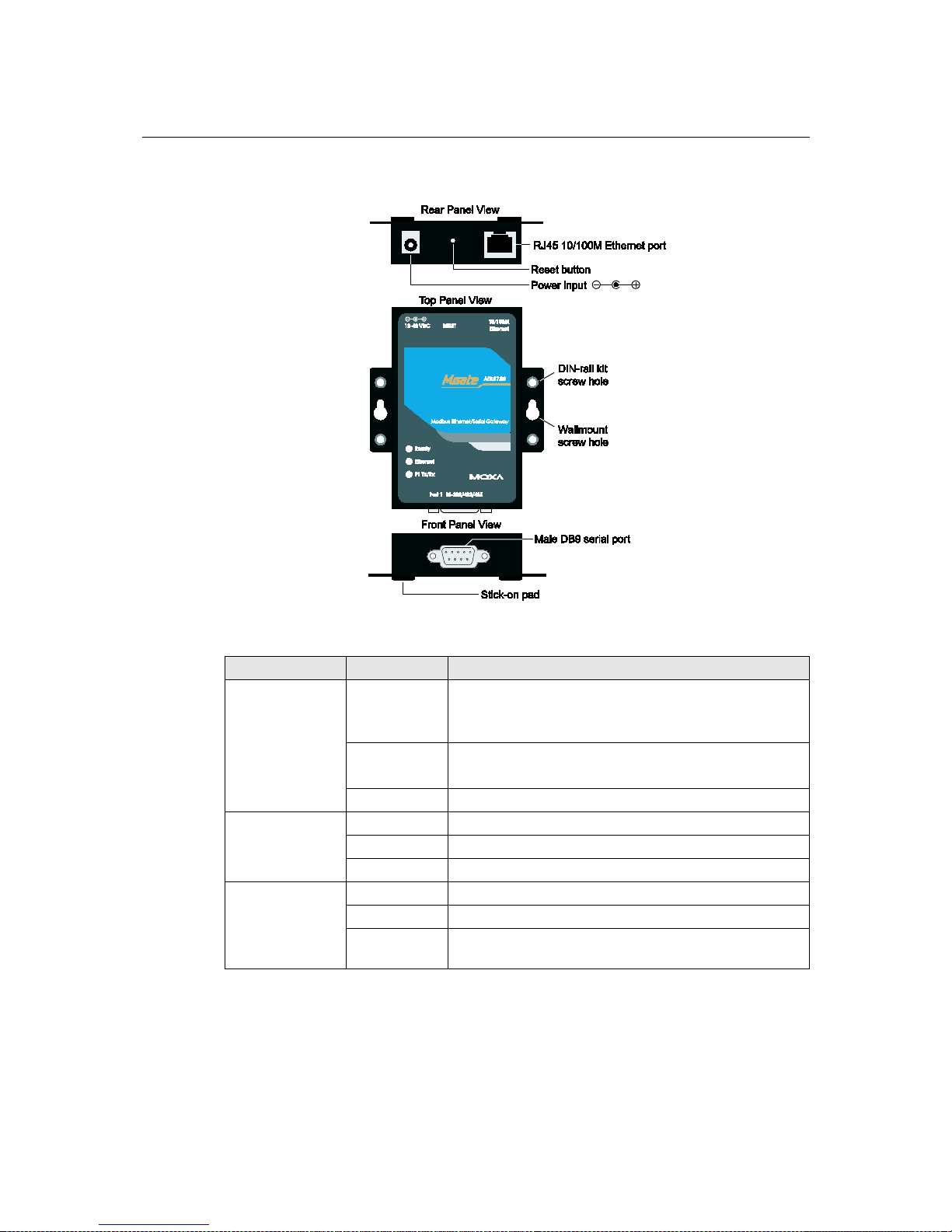
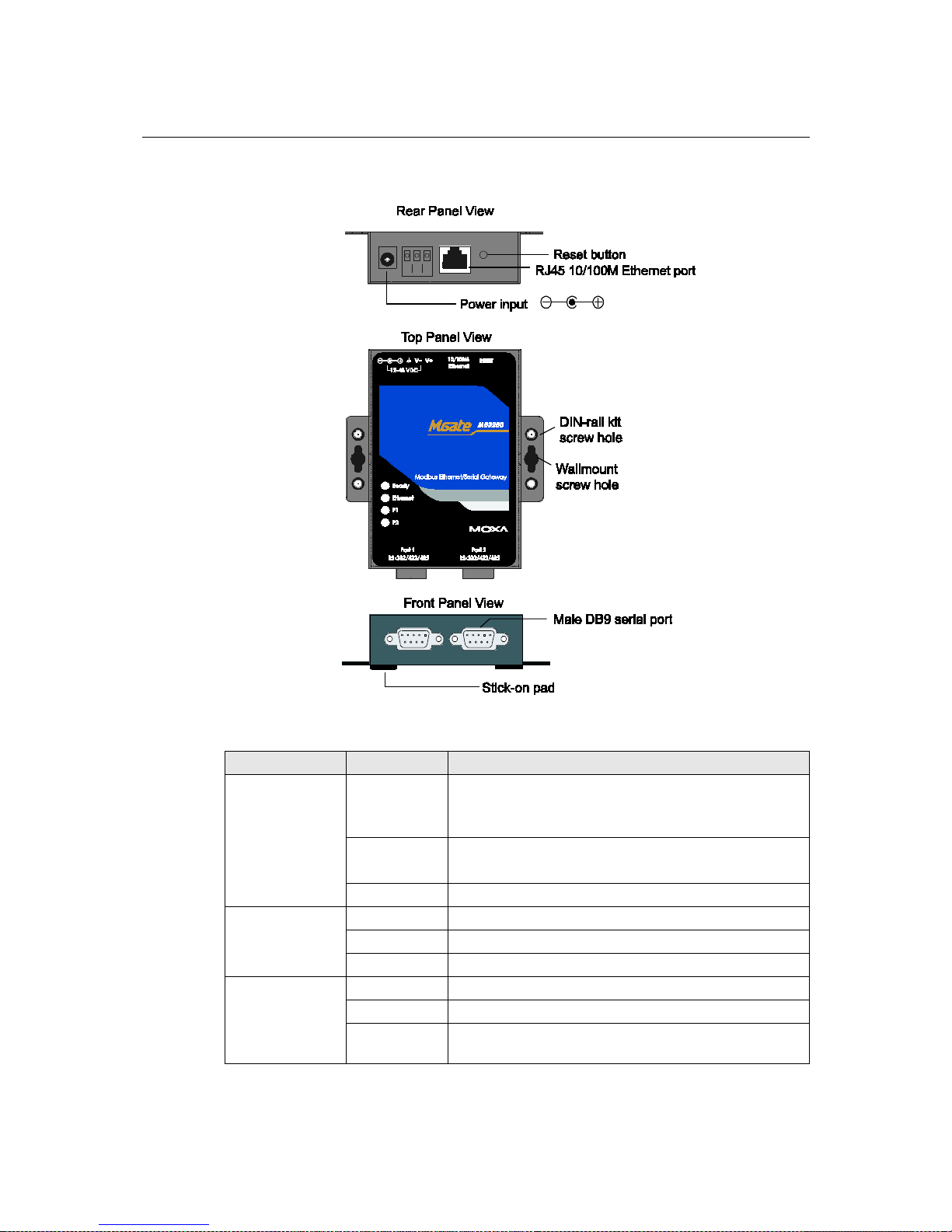
Panel Layout
LED Indicators
Name Color Function
Ready
Red
Steady on: Powe r is on and unit is booting up.
Blinking: Indicates an IP conflict, or DHCP or BOOTP
server is not responding properly.
Green
Steady on: Power is on and unit is functioning normally.
Blinking: U nit is responding to software Locate function.
Off Power is off, or power error condition exists.
Ethernet
Orange 10 Mbps Ethernet connection.
Green 100 Mbps Ethernet connection.
Off Ethernet cable is disconnected, or has a short.
P1 Tx/Rx
Orange Serial port is receiving data.
Green Serial port is transmitting data.
Off
No data is being transmitted or rec e ived through the serial
port.
Page 14
MGate MB3000 User’s Manual Hardware: MB3180
3-3
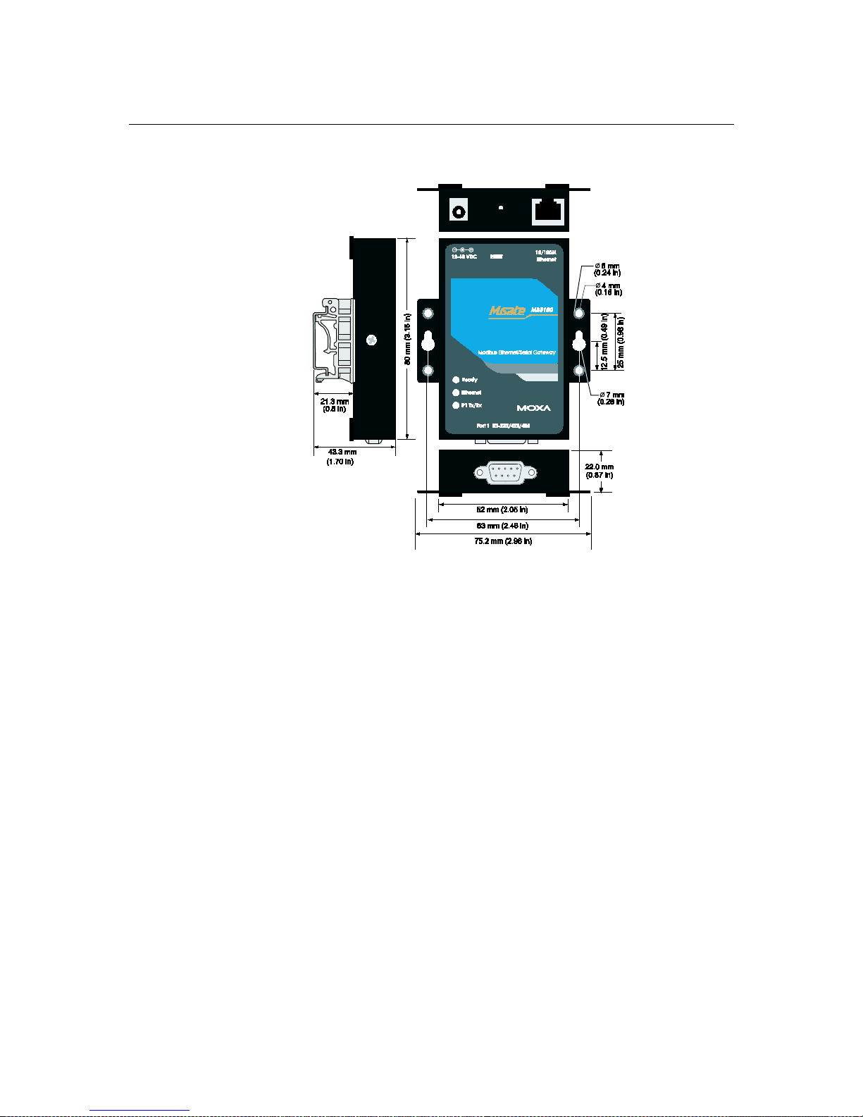
Dimensions
Page 15
MGate MB3000 User’s Manual Hardware: MB3180
3-4
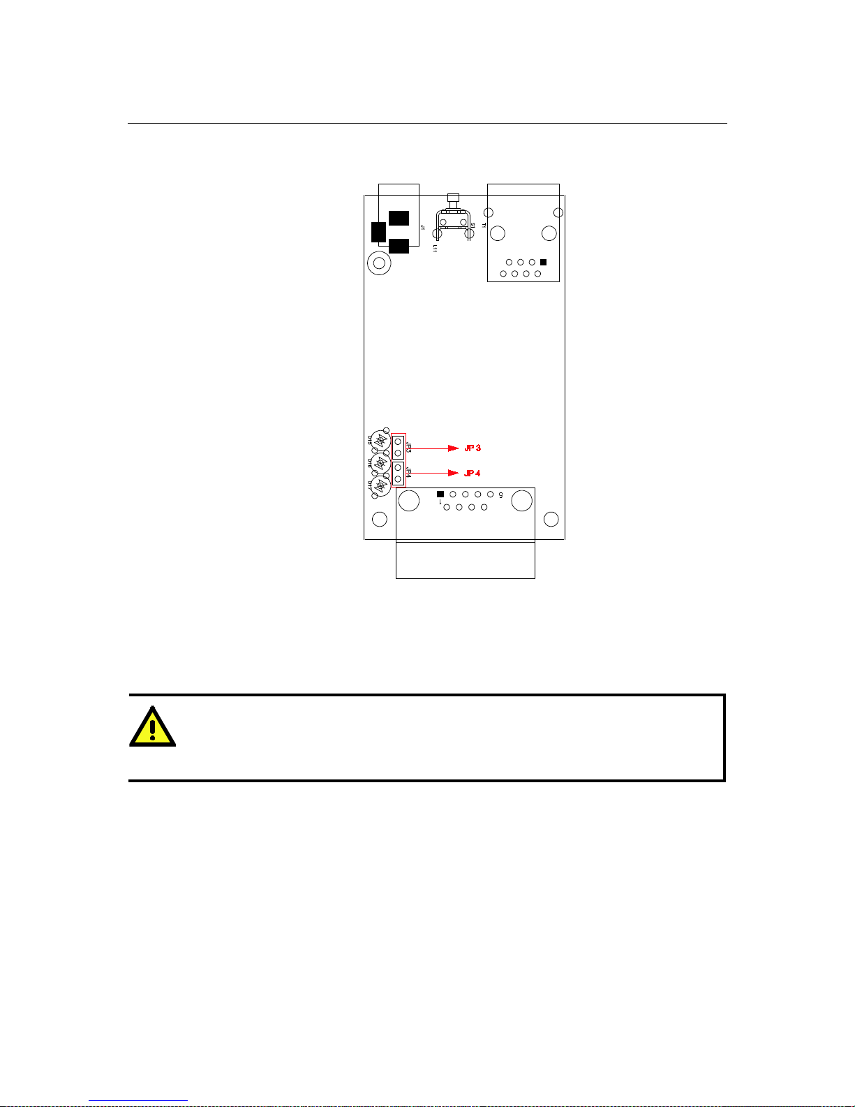
Jumpers
To set the pull high/low resistors to 150 KΩ, leave jumpers JP3 and JP4 open (not shorted). This
is the default setting.
To set the pull high/low resistors to 1 KΩ, short jumpers JP3 and JP4 with jumper caps.
ATTENTION
Do not use the 1 KΩ pull high/low setting on the MGate MB3000 when using the RS-232 interface.
Doing so will degrade the RS-232 signals and reduce the effective communication distance.
Page 16
MGate MB3000 User’s Manual Hardware: MB3180
3-5
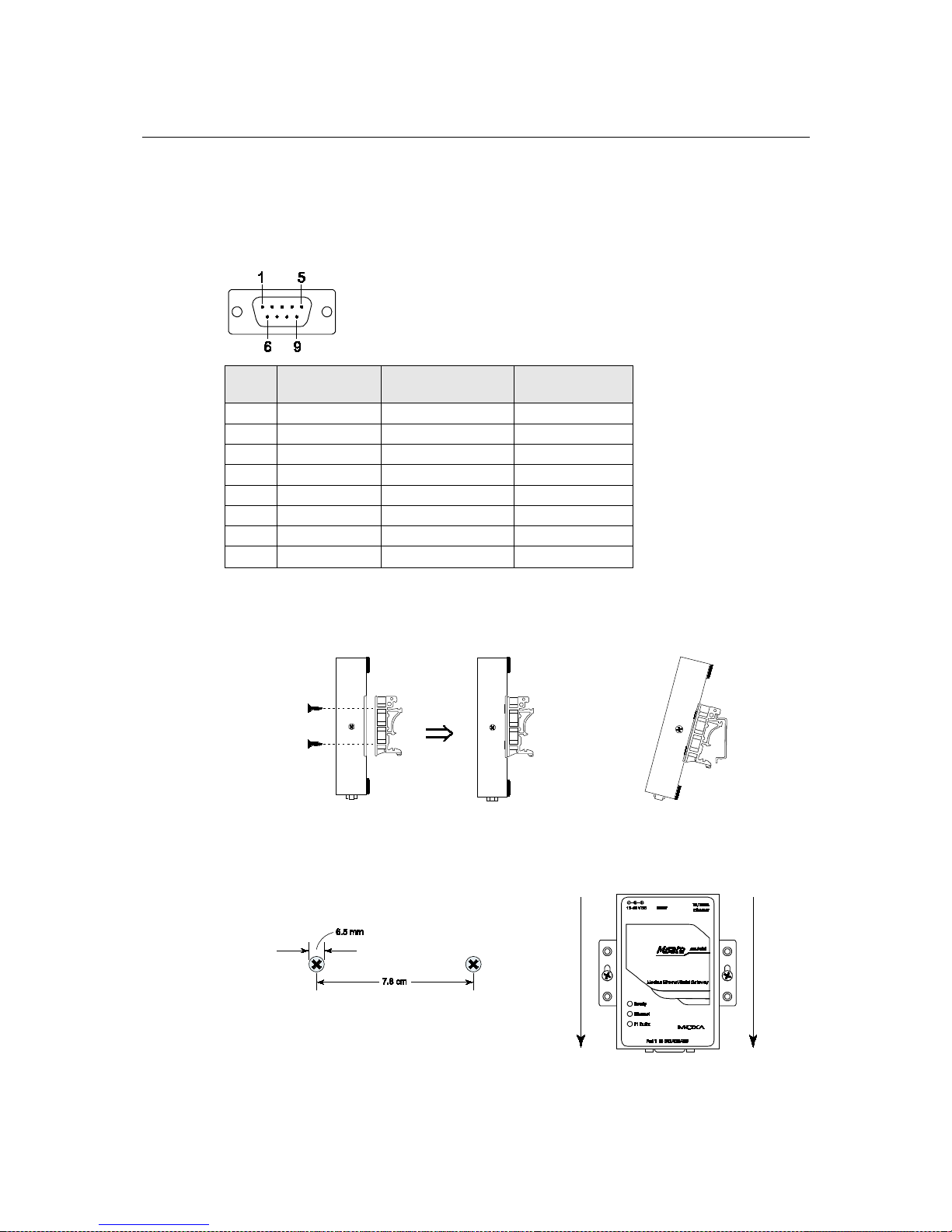
Pin Assignments
DB9 (Male)
The MGate MB3000 uses DB9 (male) serial ports to connect Modbus RTU or ASCII devices. Each
port supports three serial interfaces: RS-232, RS-422, and RS-485 (both 2 and 4-wire).
Pin RS-232
RS-422
RS-485 (4W)
RS-485 (2W)
1
DCD
TxD-
---
2
RxD
TxD+
---
3
TxD
RxD+
Data+
4
DTR
RxD-
Data-
5
GND
GND
GND
6
DSR
---
---
7
RTS
---
---
8
CTS
---
---
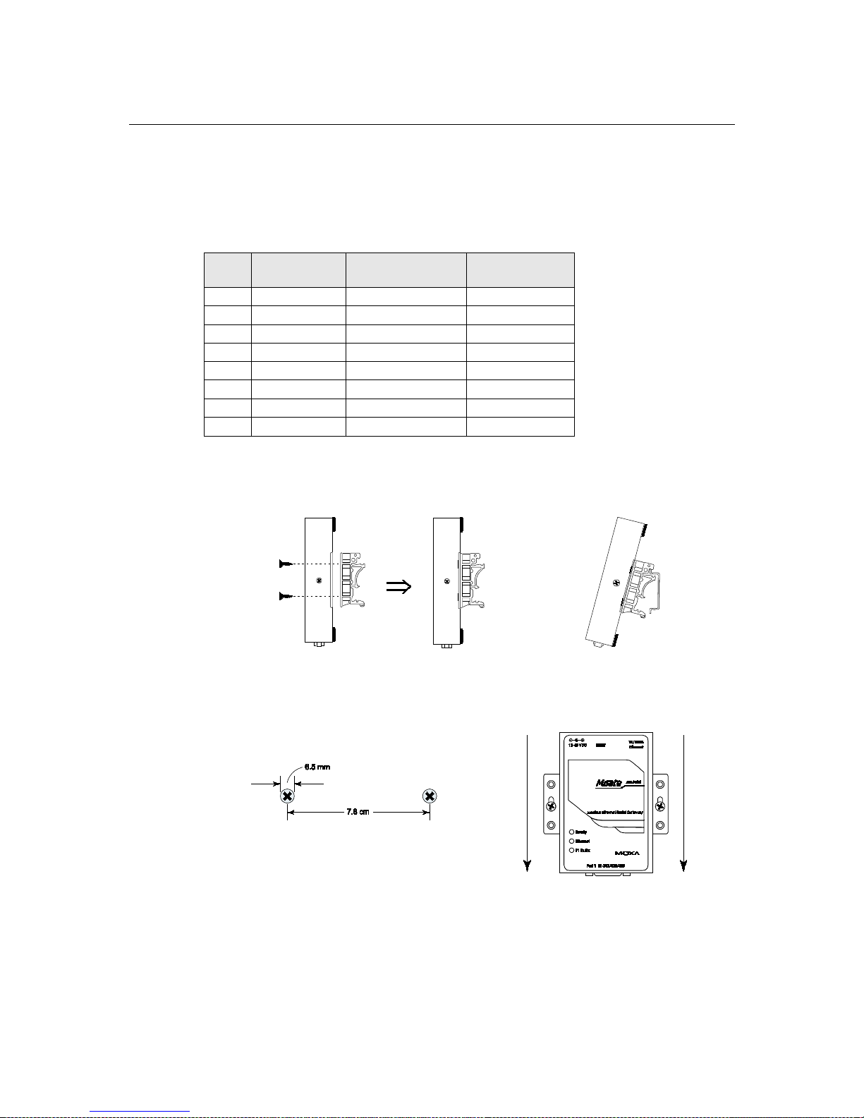
DIN-Rail, Wall Mounting
Mounting on a DIN-rail: Attach the DIN-rail accessories and latch the unit onto the DIN-rail as
shown. The DIN-rail kit is ordered separately.
Mounting on the wall: Place two screws in the wall and slide the unit onto the screws as shown. The
head of each screw 6.5 mm or less in diameter, and the shaft should be 3 mm or less in diameter.
Make sure to leave about 2 mm of space between the head and the wall.
Page 17

MGate MB3000 User’s Manual Hardware: MB3180
3-6
Specifications
LAN
Ethernet
10/100 Mbps, RJ45, Auto MDI/MDIX
Protection
Built-in 1.5 KV magnetic isolation
Serial Interface
Interface
RS-232/422/485
No. of Ports
1 port
Connector Type
DB9 (male)
Signals
RS-232:
TxD, RxD, RTS, CTS, DTR, DSR, DCD, GND
RS-422:
Tx+, Tx -, Rx+, Rx-, GND
RS-485 (2-wire):
Data+, Data-, GND
RS-485 (4-wire)
Tx+, Tx -, Rx+, Rx-, GND
Serial Line Protection
15 KV ESD for all signals
RS-485 Data Direction
Patented ADDC™
Serial Communication Parameters
Parity
None, Even, Odd, Space, Mark
Data Bits
7, 8
Stop Bits
1, 2
Flow Control
RTS/CTS, XON/XOFF
Transmission Speed
50 bps to 921.6 Kbps
Software Features
Operation Mode
RTU Slave, RTU Master, ASCII Slave, ASCII Master
Utilities
MGate Manager
Multi-Masters and
Multi-Request
16 simultaneous TCP masters, 32 simultaneous requests for ea ch TCP
master
Power Requirements
Power Input
12 to 48 VDC
Power Connector
Power jack
Power Consumption
200 mA@12 VDC, 60 mA@48 VDC
Environment
Operating Temperature
0 to 55°C (32 to 13 1°F), 5 to 95%RH
Storage Temperature
-20 to 85°C (-4 to 185°F), 5 to 95% RH
Warranty
Period
5 years
Page 18

4
4
Chapter 4 Hardware: MB3280
This chapter provides hardware information for the MGate MB3280.
The following topics are covered:
Panel Layout
LED Indicators
Dimensions
Jumpers
Pin Assignments
DB9 (Male)
DIN-Rail, Wall Mounting
Specifications
Page 19
MGate MB3000 User’s Manual Hardware: MB3280
4-2
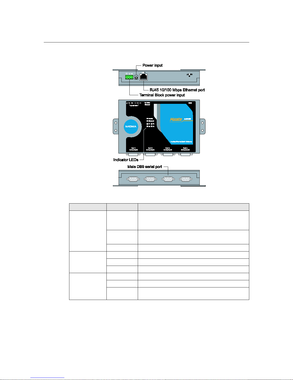
Panel Layout
LED Indicators
Name Color Function
Ready
Red
Steady on: Power is on and unit is booting up.
Blinking: Indicates an IP conflict, or DHCP or BOOTP
server is not responding properly.
Green
Steady on: Power is on and unit is functioning normally.
Blinking: Unit is responding to software Locate function.
Off Power is off, or power error condition exists.
Ethernet
Orange 10 Mbps Ethernet connection.
Green 100 Mbps Ethernet connection.
Off Ethernet cable is disconnected, or has a short.
P1 and P2
Orange Serial port is receiving data.
Green Serial port is transmitting data.
Off
No data is being transmitted or rec e ived through the serial
port.
Page 20

MGate MB3000 User’s Manual Hardware: MB3280
4-3
Dimensions
Page 21

MGate MB3000 User’s Manual Hardware: MB3280
4-4
Jumpers
To add a 120 Ω termination resistor, set switch 3 on the port’s assigned DIP switch to ON; set
switch 3 to OFF (the d e fault setting) to disable the terminatio n re sisto r.
To set the pull high/low resistors to 150 KΩ, set swi tches 1 and 2 on the port’s assigne d DIP switch
to OFF. This is the default setting.
To set the pull high/low resistors to 1 KΩ, set switches 1 and 2 on the port’s assigned DI P switch to
ON.
Switch 4 on the port's assigned DIP switch is reserved.
ATTENTION
Do not use the 1 KΩ pull high/low setting on the MGate MB3000 when using the RS-232 interface.
Doing so will degrade the RS-232 signals and reduce the effective communication distance.
Page 22
MGate MB3000 User’s Manual Hardware: MB3280
4-5
Pin Assignments
DB9 (Male)
The MGate MB3000 uses DB9 (male) serial ports to connect Modbus RTU or ASCII devices. Each
port supports three serial interfaces: RS-232, RS-422, and RS-485 (both 2 and 4-wire).
Pin RS-232
RS-422
RS-485 (4W)
RS-485 (2W)
1
DCD
TxD-
---
2
RxD
TxD+
---
3
TxD
RxD+
Data+
4
DTR
RxD-
Data-
5
GND
GND
GND
6
DSR
---
---
7
RTS
---
---
8
CTS
---
---
DIN-Rail, Wall Mounting
Mounting on a DIN-rail: Attach the DIN-rail accessories and latch the unit onto the DIN-rail as
shown. The DIN-rail kit is order e d separately.
Mounting on the wall: Place two screws in the wall and slide the unit onto the screws as shown. The
head of each screw 6.5 mm or less in diameter, and the shaft should be 3 mm or less in diameter.
Make sure to leave about 2 mm of space between the head and the wall.
Page 23

MGate MB3000 User’s Manual Hardware: MB3280
4-6
Specifications
LAN
Ethernet
10/100 Mbps, RJ45, Auto MDI/MDIX
Protection
Built-in 1.5 KV magnetic isolation
Serial Interface
Interface
RS-232/422/485
No. of Ports
2 ports
Connector Type
DB9 (male)
Signals
RS-232:
TxD, RxD, RTS, CTS, DTR, DSR, DCD, GND
RS-422:
Tx+, Tx -, Rx+, Rx-, GND
RS-485 (2-wire):
Data+, Data-, GND
RS-485 (4-wire)
Tx+, Tx -, Rx+, Rx-, GND
Serial Line Protection
15 KV ESD for all signals
RS-485 Data Direction
Patented ADDC™
Serial Communication Parameters
Parity
None, Even, Odd, Space, Mark
Data Bits
7, 8
Stop Bits
1, 2
Flow Control
RTS/CTS, XON/XOFF
Transmission Speed
50 bps to 921.6 Kbps
Software Features
Operation Mode
RTU Slave, RTU Master, ASCII Slave, ASCII Master
Utilities
MGate Manager
Multi-Masters and
Multi-Request
16 simultaneous TCP masters, 32 simultaneous requests for ea ch TCP
master
Power Requirements
Power Input
250 mA@12 VDC, 90 mA@48 VDC
Power Socket
Power jack and terminal block
Power Consumption
250 mA (max.)
Environment
Operating Temperature
0 to 55°C (32 to 13 1°F), 5 to 95%RH
Storage Temperature
-20 to 85°C (-4 to 185°F), 5 to 95% RH
Warranty
Period
5 years
Page 24

5
5
Chapter 5 Hardware: MB3480
This chapter provides hardware information for the MGate MB3480.
The following topics are covered:
Panel Layout
LED Indicators
Dimensions
Jumpers
Pin Assignments
DB9 (Male)
DIN-Rail, Wall Mounting
Specifications
Page 25
MGate MB3000 User’s Manual Hardware: MB3480
5-2
Panel Layout
LED Indicators
Name Color Function
Ready
Red
Steady on: Power is on and unit is booting up.
Blinking: Indicates an IP conflict, or DHCP or BOOTP
server is not responding properly.
Green
Steady on: Power is on and unit is functioning normally.
Blinking: U nit is responding to software Locate function.
Off Power is off, or power error condition exists.
Ethernet
Orange 10 Mbps Ethernet connection.
Green 100 Mbps Ethernet connection.
Off Ethernet cable is disconnected, or has a short.
P1, P2 P3, P4
Orange Serial port is receiving data.
Green Serial port is transmitting data.
Off
No data is being transmitted or rec e ived through the serial
port.
Page 26

MGate MB3000 User’s Manual Hardware: MB3480
5-3
Dimensions
Page 27
MGate MB3000 User’s Manual Hardware: MB3480
5-4
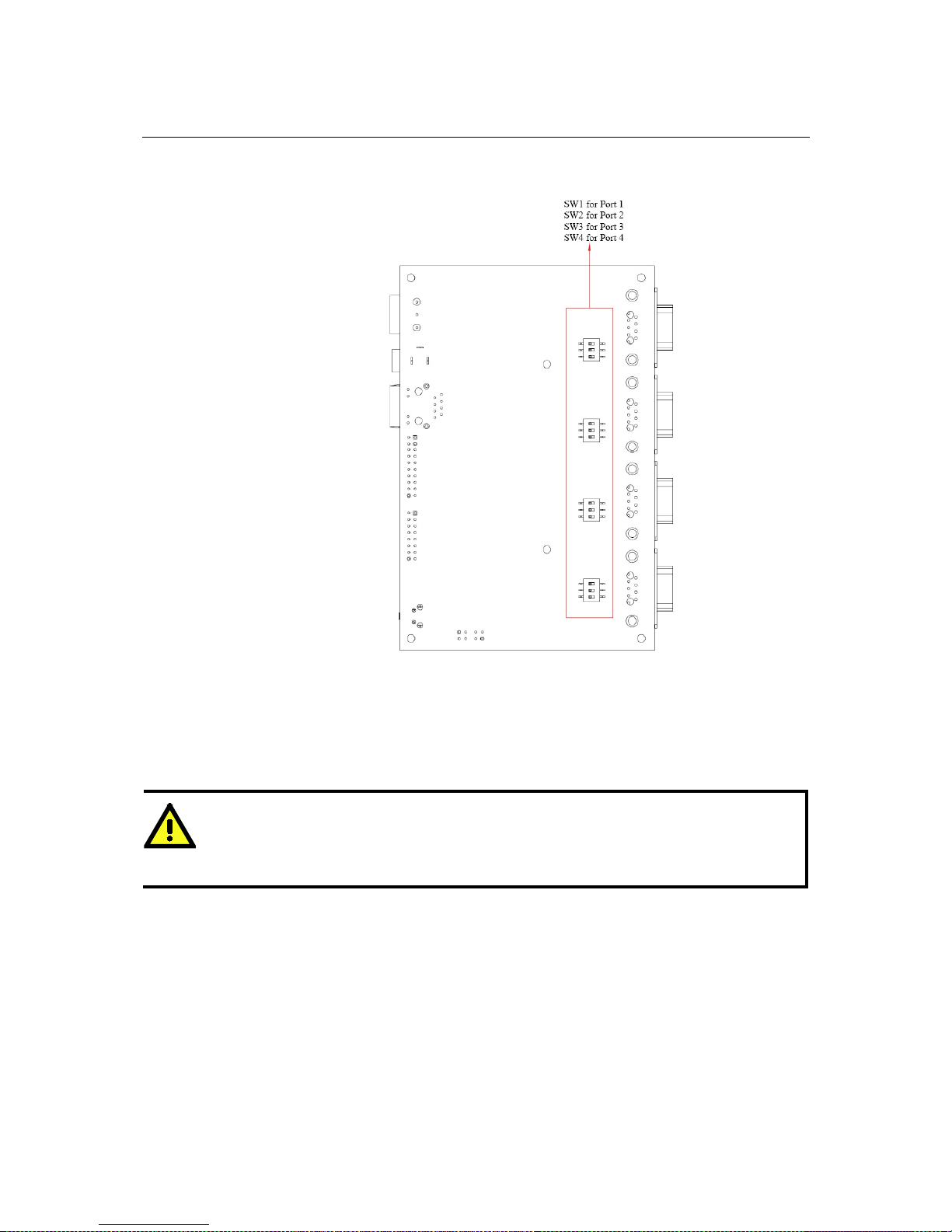
Jumpers
To add a 120 Ω termination resistor, set switch 3 on the port’s assigned DIP switch to ON; set
switch 3 to OFF (the default setting) to disable the termination resistor.
To set the pull high/low resistors to 150 KΩ, set swi tches 1 an d 2 on the port’s assigne d DIP switch
to OFF. This is the default setting.
T o set the pull high/low resistors to 1 KΩ, s et swit ches 1 and 2 on the port’ s assigned DIP switch to
ON.
ATTENTION
Do not use the 1 KΩ pull high/low setting on the MGate MB3000 when using the RS-232 interface.
Doing so will degrade the RS-232 signals and reduc e the effective communication d istance.
Page 28

MGate MB3000 User’s Manual Hardware: MB3480
5-5
Pin Assignments
DB9 (Male)
The MGate MB3000 uses DB9 (male) serial ports to connect Modbus RTU or ASCII devices. Each
port supports three serial interfaces: RS-232, RS-422, and RS-485 (both 2 and 4-wire).
Pin RS-232
RS-422
RS-485 (4W)
RS-485 (2W)
1
DCD
TxD-
---
2
RxD
TxD+
---
3
TxD
RxD+
Data+
4
DTR
RxD-
Data-
5
GND
GND
GND
6
DSR
---
---
7
RTS
---
---
8
CTS
---
---
Page 29

MGate MB3000 User’s Manual Hardware: MB3480
5-6
DIN-Rail, Wall Mounting
Mounting on a DIN-rail: You will first need to attach the mounting plates (included) to the unit.
Attach the DIN-rail accessories to the mounting plates and latch the unit onto the DIN-
rail as shown.
The DIN-rail kit is ordered separately.
Mounting on the wall: You will first need to attach the mounting plates to the unit. Place four
screws in the wall and slide the unit onto the screws as shown.
The head of each screw should be
6 mm or less in diameter, and the shaft should be 3 mm or less in
diameter. Make sure to leave about 5 mm of space between the head and the wall.
Page 30

MGate MB3000 User’s Manual Hardware: MB3480
5-7
Specifications
LAN
Ethernet
10/100 Mbps, RJ45, Auto MDI/MDIX
Protection
Built-in 1.5 KV magnetic isolation
Serial Interface
Interface
RS-232/422/485
No. of Ports
4 ports
Connector Type
DB9 (male)
Signals
RS-232:
TxD, RxD, RTS, CTS, DTR, DSR, DCD, GND
RS-422:
Tx+, Tx -, Rx+, Rx-, GND
RS-485 (2-wire):
Data+, Data-, GND
RS-485 (4-wire)
Tx+, Tx -, Rx+, Rx-, GND
Serial Line Protection
15 KV ESD for all signals
RS-485 Data Direction
Patented ADDC™
Serial Communication Parameters
Parity
None, Even, Odd, Space, Mark
Data Bits
7, 8
Stop Bits
1, 2
Flow Control
RTS/CTS, XON/XOFF
Transmission Speed
50 bps to 921.6 Kbps
Software Features
Operation Mode
RTU Slave, RTU Master, ASCII Slave, ASCII Master
Utilities
MGate Manager
Multi-Masters and
Multi-Request
16 simultaneous TCP masters, 32 simultaneous requests for ea ch TCP
master
Power Requirements
Power Input
12 to 48 VDC
Power Socket
Power jack and terminal block
Power Consumption
460 mA@12 VDC, 170 mA@48 VDC
Environment
Operating Temperature
0 to 55°C (32 to 13 1°F), 5 to 95%RH
Storage Temperature
-20 to 85°C (-4 to 185°F), 5 to 95% RH
Warranty
Period
5 years
Page 31

6
6
Chapter 6 Hardware: MB3170, MB3170I
This chapter provides hardware information for the MGate MB3170 and MB3170I.
The following topics are covered:
Panel Layout
LED Indicators
Dimensions
Jumpers
Pin Assignments
DB9 (Male)
Terminal Block (RS-422, RS-485)
Power Input, Relay Output
DIN-Rail, Wall Mounting
Specifications
Page 32

MGate MB3000 User’s Manual Hardware: MB3170, MB3170I
6-2
Panel Layout
LED Indicators
Name
Color
Function
PWR1 Red
Power is being supplied to the power input.
PWR2 Red
Power is being supplied to the power input.
RDY
Red
Steady on: Power is on and unit is booting up.
Blinking: Indicates an IP conflict, or DHCP or BOOTP
server is not responding properly.
Green
Steady on: Power is on and unit is functioning normally.
Blinking: U nit is responding to software Locate function.
Off
Power is off, or power error condition exists.
Ethernet
Orange
10 Mbps Ethernet connection.
Green
100 Mbps Ethernet connection.
Off
Ethernet cable is disconnected, or has a short.
P1
Orange
Serial port is receiving data.
Green
Serial port is transmitting data.
Off
No data is being transmitted or rec e ived through the serial
port.
Page 33

MGate MB3000 User’s Manual Hardware: MB3170, MB3170I
6-3
Dimensions
Page 34

MGate MB3000 User’s Manual Hardware: MB3170, MB3170I
6-4
Jumpers
The DIP switches are located beneath the DIP switch panel on the side of the unit.
To add a 120 Ω termination resistor, set switch 3 to ON; set switch 3 to OFF (the default setting) to
disable the termination resistor.
To set the pull high/low resistors to 150 KΩ, set switches 1 and 2 to OFF. This is the default
setting.
To set the pull high/low resistors to 1 KΩ, set switches 1 and 2 to ON.
Switch 4 on the port’s assigned DIP switch is reserve d.
ATTENTION
Do not use the 1 KΩ pull high/low setting on the MGate MB3000 when using the RS-232 interface.
Doing so will degra d e the RS-23 2 signals and reduce the effective communication distance.
Page 35

MGate MB3000 User’s Manual Hardware: MB3170, MB3170I
6-5
Pin Assignments
DB9 (Male)
The MGate MB3170 and MB3170I use a DB9 (male) serial port for RS-232 connections to Modbus
RTU or ASCII devices.
Pin RS-232
1
DCD
2
RxD
3
TxD
4
DTR
5
GND
6
DSR
7
RTS
8
CTS
Terminal Block (RS-422, RS-485)
The MGate MB3170 and MB3170I use a terminal block connector for RS-422 and RS-485
connections t o Modbus RTU or ASCII devices.
Pin
RS-422
RS-485 (4W)
RS-485 (2W)
1
TxD+
---
2
TxD-
--- 3 RxD+
Data+
4
RxD-
Data-
5
GND
GND
Page 36

MGate MB3000 User’s Manual Hardware: MB3170, MB3170I
6-6
Power Input, Relay Output
V2+
V2- V1+
V1-
Shielded
Ground
DC Power
Input 1
DC Power
Input 1
Relay
Output
Relay
Output
DC Power
Input 2
DC Power
Input 2
DIN-Rail, Wall Mounting
There are two sliders on the back of the unit for DIN-rail and wall mounting.
Mounting on a DIN-rail: Pull out the bottom slider, latch the unit onto the DIN-rail, and push the
slider back in.
Mounting on the wall: Pull out both the top and bottom sliders and align the screws accordingly.
Page 37

MGate MB3000 User’s Manual Hardware: MB3170, MB3170I
6-7
Specifications
LAN
Ethernet
10/100 Mbps, RJ45, Auto MDI/MDIX
Protection
Built-in 1.5 KV magnetic isolation
Serial Interface
Interface
RS-232/422/485
No. of Ports
1 port
Connector Type
DB9 (male) for RS-232, terminal block for RS-422/485
Signals
RS-232:
TxD, RxD, RTS, CTS, DTR, DSR, DCD, GND
RS-422:
Tx+, Tx -, Rx+, Rx-, GND
RS-485 (2-wire):
Data+, Data-, GND
RS-485 (4-wire):
Tx+, Tx -, Rx+, Rx-, GND
Serial Line Protection
15 KV ESD for all signals
RS-485 Data Direction
Patented ADDC™
Serial Communication Parameters
Parity
None, Even, Odd, Space, Mark
Data Bits
7, 8
Stop Bits
1, 2
Flow Control
RTS/CTS, XON/XOFF
Transmission Speed
50 bps to 921.6 Kbps
Software Features
Operation Mode
RTU Slave, RTU Master, ASCII Slave, ASCII Master
Utilities
MGate Manager
Multi-Masters and
Multi-Request
16 simultaneous TCP masters, 32 simultaneous requests for ea ch TCP
master
Power Requirements
Power Input
12 to 48 VDC
Power Socket
Terminal block
Power Consumption
MB3170: 400 mA@12 VDC, 130 mA@48 VDC
MB3170I: 405 mA@12 VDC, 140 mA@48 VDC
Relay Output
1 digital relay output to alarm (normal close):
Current carrying capacity 1 A @ 30 VDC
Environment
Operating Temperature
0 to 55°C (32 to 13 1°F), 5 to 95%RH
-40 to 75°C (-40 to 167°F), 5 to 95%PH for “-T” models
Storage Temperature
-40 to 85°C (-40 to 185°F), 5 to 95% RH
Warranty
Period
5 years
Page 38

7
7
Chapter 7 Hardware: MB3270, MB3270I
This chapter provides hardware information for the MGate MB3270 and MB3270I. The following
topics are covered:
Panel Layout
LED Indicators
Dimensions
Jumpers
Pin Assignments
DB9 (Male)
Power Input, Relay Output
DIN-Rail, Wall Mounting
Specifications
Page 39

MGate MB3000 User’s Manual Hardware: MB3270, MB3270I
7-2
Panel Layout
LED Indicators
Name
Color
Function
PWR1 Red
Power is being supplied to the power input.
PWR2 Red
Power is being supplied to the power input.
RDY
Red
Steady on: Power is on and unit is booting up.
Blinking: Indicates an IP conflict, or DHCP or
BOOTP server is
not responding properly.
Green
Steady on: Power is on and unit is functioning normally.
Blinking: U nit is responding to software Locate function.
Off
Power is off, or power error condition exists.
Ethernet
Orange
10 Mbps Ethernet connection.
Green
100 Mbps Ethernet connection.
Off
Ethernet cable is disconnected, or has a short.
P1, P2
Orange
Serial port is receiving data.
Green
Serial port is transmitting data.
Off
No data is being tra nsmit ted or re ceiv ed th rough the serial port.
Page 40

MGate MB3000 User’s Manual Hardware: MB3270, MB3270I
7-3
Dimensions
Page 41

MGate MB3000 User’s Manual Hardware: MB3270, MB3270I
7-4
Jumpers
The DIP switches are located beneath the DIP switch panel on the side of the unit.
To add a 120 Ω termination resistor, set switch 3 on the port’s assigned DIP switch to ON; set
switch 3 to OFF (the default setting) to disable the termination resistor.
To set the pull high/low resistors to 150 KΩ, set swi tches 1 an d 2 on the port’s assigne d DIP switch
to OFF. This is the default setting.
To set the pull high/low resistors to 1 KΩ, set switches 1 and 2 on the port’ s assigned DIP switch to
ON.
Switch 4 on the port's assigned DIP switch is reserved.
ATTENTION
Do not use the 1 KΩ pull high/low setting on the MGate MB3000 when using the RS-232 interface.
Doing so will degrade the RS-232 signals and reduce the effective communication distance.
Page 42

MGate MB3000 User’s Manual Hardware: MB3270, MB3270I
7-5
Pin Assignments
DB9 (Male)
The MGate MB3000 uses DB9 (male) serial ports to connect Modbus RTU or ASCII devices. Each
port supports three serial interfaces: RS-232, RS-422, and RS-485 (both 2 and 4-wire).
Pin RS-232
RS-422
RS-485 (4W)
RS-485 (2W)
1
DCD
TxD-
---
2
RxD
TxD+
---
3
TxD
RxD+
Data+
4
DTR
RxD-
Data-
5
GND
GND
GND
6
DSR
---
---
7
RTS
---
---
8
CTS
---
---
Power Input, Relay Output
V2+ V2-
V1+ V1-
Shielded
Ground
DC Power
Input 1
DC Power
Input 1
Relay
Output
Relay
Output
DC Power
Input 2
DC Power
Input 2
Page 43

MGate MB3000 User’s Manual Hardware: MB3270, MB3270I
7-6
DIN-Rail, Wall Mounting
There are two sliders on the back of the unit for DIN-rail and wall mounting.
Mounting on a DIN-rail: Pull out the bottom slider, latch the unit onto the DIN-rail, and push the
slider back in.
Mounting on the wall: Pull out both the top and bottom sliders and align the screws accordingly.
Page 44

MGate MB3000 User’s Manual Hardware: MB3270, MB3270I
7-7
Specifications
LAN
Ethernet
10/100 Mbps, RJ45, Auto MDI/MDIX
Protection
Built-in 1.5 KV magnetic isolation
Serial Interface
Interface
RS-232/422/485
No. of Ports
2 ports
Connector Type
DB9 (male)
Signals
RS-232:
TxD, RxD, RTS, CTS, DTR, DSR, DCD, GND
RS-422:
Tx+, Tx -, Rx+, Rx-, GND
RS-485 (2-wire):
Data+, Data-, GND
RS-485 (4-wire):
Tx+, Tx -, Rx+, Rx-, GND
Serial Line Protection
15 KV ESD for all signals
RS-485 Data Direction
Patented ADDC™
Serial Communication Parameters
Parity
None, Even, Odd, Space, Mark
Data Bits
7, 8
Stop Bits
1, 2
Flow Control
RTS/CTS, XON/XOFF
Transmission Speed
50 bps to 921.6 Kbps
Software Features
Operation Mode
RTU Slave, RTU Master, ASCII Slave, ASCII Master
Utilities
MGate Manager
Multi-Masters and
Multi-Request
16 simultaneous TCP masters, 32 simultaneous requests for ea ch TCP
master
Power Requirements
Power Input
12 to 48 VDC
Power Socket
Terminal block
Power Consumption
MB3270: 410 mA@12 VDC, 145 mA@48 VDC
MB3270I: 470 mA@12 VDC, 150 mA@48 VDC
Relay Output
1 digital relay output to alarm (normal close):
Current carrying capacity 1 A @ 30 VDC
Environment
Operating Temperature
0 to 55°C (32 to 13 1°F), 5 to 95%RH
-
40 to 75°C (-40 to 167°F), 5 to 95%PH for advanced models with “-
T”
option
Storage Temperature
-40 to 85°C (-40 to 185°F), 5 to 95% RH
Warranty
Period
5 years
Page 45

8
8
Chapter 8 Typical Applications
In this chapter, we introduce four typical Modbus applications.
Ethernet Masters with Multiple Serial Slaves
Serial Masters with Multiple Ethernet Slaves
Modbus TCP Masters with ASCII and RTU Slaves
Serial Master with Serial Slaves over Internet
Page 46

MGate MB3000 User’s Manual Ty pi cal Applications
8-2
Ethernet Masters with Multiple Serial Slaves
Connect all Modbus devices over an Ethernet network
Most modern PLCs and host computers support Modbus TCP over Ethernet. In order to access
discrete Modbus RTU/ASCII devices for data collection and control, they can rely on the MGate
MB3000 Modbus gateway.
The MGate MB3000 supports Modbus TCP with up to 16 simultaneous connections. The serial
interface support s both RS-232 an d RS-422/485, selectable through software. Each serial port can be
connected to one RS-232 or RS-422 serial device, or to 31 RS-485 serial devices.
Serial Masters with Multiple Ethernet Slaves
Link a serial master device with Ethernet slave devices
Many HMI (Human Machine Interface) systems use a serial interface to connect to a discrete DCS
(Data Control System). However, many DCSs are n ow Ethernet-based and operate as a Modbus TCP
slave device.
The MGate MB3000 Modbus gateway can link a serial-based HMI to distributed DCSs over an
Ethernet network. Up to 32 Modbus TCP slave devices are supported by each MGate MB3000.
Page 47

MGate MB3000 User’s Manual Ty pi cal Applications
8-3
Modbus TCP Masters with ASCII and RTU Slaves
Link TCP master devices with both ASCII and RTU serial devices
simultaneously
When integrating Modb us networks, you may encounter different Modbus serial networks that use
different baudrates or a different protocol. Modbus ASCII might be used by some devices, while
Modbus RTU is used by other devices.
The two and four-port MGate models can integrate serial Modbus networks that use different
parameters or protocols. You can configure each serial port to a specific Modbus serial environment,
set up a slave ID map. After configuration, only the gateway will be visible to Modbus TCP masters,
and all serial devices will be integrated behind it.
Serial Master with Serial Slaves over Internet
Let Modbus serial devices communicate over the Internet
Many Modbus devices communicate over RS-485, which lim its t h e number of devices in a network
to 32 and the transmission distance to 1.2 km.
With the MGate MB3000 Modbus gateway, you can lin k all Modbus devices over a n Ethernet
network. Up to 32 Modbus gateways can be installed in a single cont rol network, so each device can
now be accessed from anywhere the TCP/IP network can reach.
Page 48

9
9
Chapter 9 Configuring the Modbus Gateway
We discuss the following topics in this chapter:
Installing the Softwa re
Startin g MGate Mana ger
Change Language Settin g
Connecting to the Unit
Broadcast Search
Specify by IP Address
Modifying the Configuration
Configure Serial Port for RTU or ASCII, Master or Slave
Configure IP Address and Other Network Settings
Configure Serial Communication Parameters
Set up Slave ID Mapping (Smart Routing)
Customize Modbus Settings
Set Up Priority Control
Accessible IP
Miscellaneous
Verifying the Location of
the Unit
Monitoring Modbus Activity
Open Traffic Monitor Window
Filter Traffic Information
Save Log to File
Upgrading Firmware
Page 49

MGate MB3000 User’s Manual Configuring the Modbus Gateway
9-2
Installing the Software
The following instructions exp la in how to install MGate Manager, a utility for configuring and
monitoring MGate MB3000 units over t he network.
1. Insert the Document and Software CD int o the CD-ROM drive. Locate and run the following
setup program to begin the installation pr ocess:
MGM_Setup_[Version]_Build_[DateTime].exe
The latest version might be named MGM_Setup_Ver1.1.0_Build_xxxxxxxx.exe, for
example:
2. You will be greeted by the Welcome window. Click Next to continue.
3. When the Select Destination Location window appears, click Next to continue. You may
change the destination directory by fir st clic king on Browse....
Page 50

MGate MB3000 User’s Manual Configuring the Modbus Gateway
9-3
4. When the Select Additional T asks window appears, click Next to c ontinue. You may select
Create a desktop icon if you would like a shortcut to MGate Manager on your desktop.
5. Click Next to start copying the software files.
6. A progress bar will appear. The procedure should take only a few seconds to complete.
Page 51

MGate MB3000 User’s Manual Configuring the Modbus Gateway
9-4
7. A mes s age w ill indicate that MGat e Manager is successfully installed. You may choose to run it
immediately by selecting Launch MGate Manager.
8. You may also open MGate Manager through Start
Programs MGate Manager
MGate Manager, as shown below.
Page 52

MGate MB3000 User’s Manual Configuring the Modbus Gateway
9-5
Starting MGate Manager
MGate Manager is a Windows-based utility that is used to configure the MGate MB3000.
Before running MGate Manager, make sure that your PC and the MGate MB3000 are connected to
the same network. Alternatively, the MGate MB3000 may be connected directly to the PC for
configuration purposes. Please refer to Chapter 2 for more details.
You may open MGate Manager from the Windows Start menu by clicking Start
Programs
MGate Manager
MGate Manager. The MGate Manager window should appear as shown
below.
Change Language Setting
If you wish to run MGate Ma nager in a di fferent language , you may click Language to change the
language setting. A dialog box showing the available languages should a ppear as shown below.
Page 53

MGate MB3000 User’s Manual Configuring the Modbus Gateway
9-6
When you click OK, MGate Manager will immediately reflect your chosen language.
ATTENTION
Use “Default Language” before contacting Moxa Technical Support.
With support for multiple languages, MGate Manager is more user-friendly and accessible.
However, if you need assistance from Moxa Technical Support, please change the language to
“Default Language”. This will prevent any misunderstandings or confusion about MGate Manager
menu items and commands as our engineers assist you.
The default language is English and will only be active for the current MGate Manager session.
When you open MGate Manager again, t he language will revert to your original setting.
Connecting to the Unit
MGate Manager needs to connect to the unit before the unit can be configured. There are two
methods to connect to the unit. Broadcast Sear ch is used to find eve ry MGate MB3000 on the LAN.
Search by IP attempts to connect to a spec ific unit by IP address, which is useful if the unit is
located outside the LAN or can only be accessed by going through a router.
Page 54

MGate MB3000 User’s Manual Configuring the Modbus Gateway
9-7
Broadcast Search
Click Broadcast Search to begin searching the LAN for all MGate MB3000 units.
When the search is complete, every MGate MB3000 that is found on the LAN will app e a r in the
window with MAC address and IP address. Simply select the one that you wish to configure.
Page 55

MGate MB3000 User’s Manual Configuring the Modbus Gateway
9-8
Specify by IP Address
Click Specify by IP Addr ess if you know the IP address of the unit and wish to conn ect to it direct ly.
A dialog box will appear. Enter the unit’s IP address and click OK.
If the search is successful, the unit will be listed in MGate Manager. Click the unit to begin
configuration.
Page 56

MGate MB3000 User’s Manual Configuring the Modbus Gateway
9-9
ATTENTION
If Search by IP Address fails to locate the MGate MB3000, the IP address that you entered might
be incorrect. Try doing the search again and re-entering the IP address carefully.
Another possibility is that the MGate MB3000 is located on the same LAN as your PC, but on a
different subnet. In this case, you can modify your PC’s IP address and/or netmask so that it is on
the same subnet as the MGate MB3000. After your PC and the MGate MB3000 are on the same
subnet, MGate Manager should be able to find the unit.
Modifying the Configuration
Once your unit is displayed in MGate Manager , select it by clicking on it. The Configuration button
will become available. Click Configuration to open the configuration window.
Page 57

MGate MB3000 User’s Manual Configuring the Modbus Gateway
9-10
Configure Serial Port for RTU or ASCII, Master or Slave
The Mode tab is where each serial port’s operation mode is configured. The operation mode
determines whether the device(s) that are connected to the serial port will operate as a master or a
slave, and whether the Modbus RTU or Modbus ASCII protocol will be used. There are four
operation modes as follows:
Mode
Description
RTU Slave
Modbus RTU slave(s) will be connected to the serial port.
RTU Master
A Modbus RTU master will be connected to the serial port.
ASCII Slave
Modbus ASCII slave(s) will be connected to the serial port.
ASCII Master
A Modbus ASCII master will be connected to the serial port.
For entry-level models (MB3180, MB3280, and MB3480), Modbus TCP masters will control
Modbus RTU/ASCII slaves, and Modbus RTU/ASCII masters will control Modbus TCP slaves.
For advanced models (MB3170, MB3270), both Modbu s TCP and Modbus RTU/ASCII masters
can control Modbus TCP and Modbus RTU/ASCII slaves.
Use the radio buttons to select the desired operation mode for each serial port on the Modbus
gateway. Select the ProCOM Enable check box located in the center of the page to enable ProCOM.
For detailed information, refer to the ProCOM function description in this manual.
Page 58

MGate MB3000 User’s Manual Configuring the Modbus Gateway
9-11
What is ProCOM?
ProCOM is a Moxa proprietary function that creates virtual serial ports on the MGate MB3000
Series to make Fieldbus gateway communications more versatile. This intelligent Fieldbus gateway
mimics the behavior of a native serial port when transmitting data to the desired destination. PCs can
use ProCOM to communicate over the Ethernet with serial devices connected to the MGate MB3000
as if they were connected to the PC’s native COM ports. This advanced feature only works with the
MGate MB3x70 Series.
How to Configure ProCOM for the MGate MB3000
If your system uses remote PCs that only support COM port behavior to control remote Modbus
devices, then ProCOM is the best solution for your system. Before using ProCOM, your PC needs to
create virtual COM ports that connect to a specific ProCOM over an Ethernet network. B y us ing
ProCOM, the MGate MB3000 will treat your PC’s COM port as if it were an additional serial port on
the MGate MB3000.
To enable this function, ProCOM mapping must be completed as follows:
Locate the MGate MB3000 with the search function, and then select the MGate MB3000 device that
you want to set Pr oCO M for, and then click ProCOM Mapping to enter the mapping dialog box, as
illustrated by the following figure s.
Page 59

MGate MB3000 User’s Manual Configuring the Modbus Gateway
9-12
On the ProCOM mapping dialog box, you can map up to four ProCOM fun ctions for each Modb us
gateway to your PC’s COM ports. The driver will generate virtaul COM ports on your PC to connect
to the selected MGate MB3000s over the network.
This way, when you send a Modbus request to ProCOM, the driver will forward your request to the
MGate MB3000 and then the MGate MB3000 will forward the request to the target Modbus device
using the pre-set Modbus device mode and Slave ID. For example, the Modbus request from
ProCOM can be redirected to a Modbus RTU/ASCII device that is behind the MGate MB3000's
serial interface, or to a Modbus TCP device through the MG ate MB3000's Ethernet port. In addition,
it can be redirected to another ProCOM port on the MGate MB3000.
Page 60

MGate MB3000 User’s Manual Configuring the Modbus Gateway
9-13
If you would l ike to change the COM port numbers, double click on the items as follows:
Page 61

MGate MB3000 User’s Manual Configuring the Modbus Gateway
9-14
Configure IP Address and Other Network Settings
The Network tab is where the unit’s network settings are configured. You can modify the Name,
Network Config uratio n, IP Address, Netmask, Default Gatew ay, and DNS. You may also
select a Password to protect the unit from unauthorized access.
Page 62

MGate MB3000 User’s Manual Configuring the Modbus Gateway
9-15
Parameter
Value
Notes
Name (an alphanumeric string)
You can enter a name to help you identif y the
unit, such as the location, function, etc.
Network
Configuration
Static IP, DHCP, BootP, or
DHCP/BootP
Select “Static IP” if you are using a fixed IP
address. Select one of the other options if the IP
address is set dynamically.
IP Address
192.168.127.254
(or other 32-bit number)
The IP (Internet Protocol) address identifies the
server on the TCP/IP network.
Netmask
255.255.255.0
(or other 32-bit number)
This
identifies the server as belonging to a Class
A, B, or C network.
Gateway
0.0.0.0
(or other 32-bit number)
This is the IP address of the router that provides
network access outside the server’s LAN.
DNS1
0.0.0.0
(or other 32-bit number)
This is the IP address of the primary domain
name server.
DNS2
0.0.0.0
(or other 32-bit number)
This is the IP address of the secondary domain
name server.
Password (an alphanumeric string)
You can set a password to prevent unauthorized
users from co nfiguring the unit. The password
will be required when anyone atte mpts to
configure the unit over the network. M odbus
operation is not affected by the password.
Confirm password
(an alphanumeric string)
Re-type the password again for confirmation.
ATTENTION
To erase an existing password, leave both the New Password and Confirm Password text input
boxes blank. The password will be erased when you click OK in the bottom right corner.
Page 63

MGate MB3000 User’s Manual Configuring the Modbus Gateway
9-16
Configure Serial Communication Parameters
The Serial tab is where each serial port’s communication parameters are configured. You can
configure Baud Rate, Parity, Stop Bit, Flo w Con trol, FIFO, and Interface Mode.
Parameter
Value
Interface Mode
RS-232
RS-422
RS-485, 2W
RS-485, 4W
Baud Rate
50 bps to 961200 bps
Parity
None, Odd, Even, Space, Mark
Stop Bits
1, 2
Flow Control
None, Xon/Xoff, RTS/CTS
UART FIFO
Enable, Disable
Page 64

MGate MB3000 User’s Manual Configuring the Modbus Gateway
9-17
Set up Slave ID Mapping (Smart Routing)
The Slave ID Map tab is where slave IDs are managed. The definitions on this tab determine how
requests will be routed by the unit.
Page 65

MGate MB3000 User’s Manual Configuring the Modbus Gateway
9-18
How Slave IDs are Mapped on the MGate MB3000
When a Modbus master requests information from a Modbus slave, the request is addressed to the
desired slave's ID, which must be unique on the network. When Modbus networks are integrated by
a Modbus gateway, complications can arise if the same slave ID is being used on dif ferent netw orks.
If this is not properly addres sed, a request sent to that slave ID would receive more than one response,
causing communication problems.
With the MGate MB3000, this situation is addressed by using a slave ID map. While configuring the
MGate, users set up a range of "virtual" slave IDs that are mapped to slave devices on a specific
Modbus network. To send a request to a s lave th at is on a dif feren t Modbus network, a master would
address the request to the appropriate virtual slave ID. The MGate then routes that request as
specified by the slave ID map.
For example, if a TCP master needs information from an ASCII slave, it addresses the request to the
correspo nding virtual slave ID as defined on the MGate's slave ID map. The MGate identifies the
request as within its virtual slave ID range and forwards the request to the Modbus ASCII network,
this time addressed to the device's actual slave ID.
Virtual slave IDs must not conflict with each other or with other TCP slave IDs.
ATTENTION
The MGate MB3000 will disregard any request that is not addressed to a virtual slave ID on its
slave ID map. If a device has not been assigned a virtual slave ID, it will not be accessible by
masters on the other side of the Modbus gateway.
With the slave ID map, smart routing is achieved for units w ith multiple serial ports. Since each
virtual slave ID is routed to a specific Modbus network, requests are not broadcast over all serial
ports. This keeps communication efficient and prevents devices on one port from slowing down the
whole system.
How Slave ID Map is Defined
The slave ID map consists of entries (channels) that specify a range of virtual IDs, the destination,
and the offset value. The offset value is used to convert the virtual ID to the actual ID.
Setting
Value
Notes
Virtual Slaves ID Range
(numeric range from
1 to 254)
This specifies the range of IDs that will be
routed to the selected set of slave devices.
For example, you can specify that IDs
between 8 and 24 be routed to the devices
on Port 3. The ID 255 is reserved for the
gateway itself
Slave ID Offset
(number between
-253 and 253)
This specifies the difference between the
virtual slave ID and the actual slave ID.
If a
slave's virtual ID is 16 and the actual ID is
5, you would set the offset to -11. This
offset is applied to the entire range of
virtual slave IDs.
When a serial port is set to RTU slave or ASCII slave mode, a virtual ID range will already be
created for you. Simple select the entry in the table and modify the range and offset as needed. For
TCP slaves, you can add an entry that assigns a range of virtual IDs to a specific IP address, using the
Remote TCP Slave IP setting.
Page 66

MGate MB3000 User’s Manual Configuring the Modbus Gateway
9-19
Slave ID Map Example
Suppose you have two ASCII slave devices on port 1 assigned to slave IDs 3 and 5. The MGate will
automatically create a virtual ID range for port 1, which you will need to modify. If slave IDs 3 and
5 are already in use by TCP slaves, the virtual ID range should be set to IDs that are not in use, such
as 20 through 22. In that case, you would specify a slave ID offset of -17, since that is the difference
between the virtual ID range and the actual slave IDs. The formula is as follows:
(Real Slave ID)
-
(Virtual Slave ID)
=
(Slave ID Offset)
3 - 20 = -17
With the slave ID map configured, a master that wants information from one of the ASCII slaves
would add ress the request to slave ID 20 or 22. The MGate would identify that the request was
addressed to a virtual slave ID in the slave ID map. The MGate would then forward the request to
port 1, applying the -17 offset to obtain the actual ID of the desired device.
Customize Modbus Settings
The Modbus tab is where certain adjustments can be made to fine tune the communication between
different Modbus networks. You can configure Initial Delay, Modbus TCP Exception, Slave
Channel, and Response Time-out.
Parameter
Value
Initial Delay
Numeric
Modbus TCP Exception
Enable or Disable
Slave Channel
Radio button
Response Time-out
Numeric
Initial Delay
Some Modbus slaves may take more time to boot up than other devices. For certain environments,
this may cause the entire system to suffer fro m repea te d exceptions during the initial boo t-up. Y ou
can force the MGate to wait af ter b oo tin g up b e fore s e ndi ng t he fir st request with the “Ini tia l
Delay” setting.
Modbus TCP Exception
The MGate MB3000 is a protocol gateway that transparently passes requests and responses between
the Ethernet and serial interfaces. In some situations, it may be necessary for the gateway to return an
exception in response to a request from a Modbus TCP master. This is enabled or disabled with the
“Modbus TCP Excep t ion” setting. When enabled, t he unit can return two types of exceptio n:
Exception
Conditions
Timeout
There is no response from the slave. Maybe the device is off-line
or the serial cable is broken.
Request dropped
There are two situations that will resul t in this exception:
The request queue is full (32 request queue for each master)
The destinat ion ID not included in the slave ID map.
Not all Modbus TCP masters require this exception, so it is up to you to dete rmine if this setting
should be enabled.
Page 67

MGate MB3000 User’s Manual Configuring the Modbus Gateway
9-20
Slave Channel and Response Timeout
According to th e Modbus standard, the time that it takes for a sl ave dev ice t o respond to a requ est is
defined by the device manufacturer (please refer to Appendix A for details). Based on this response
time, a master can be configured to wait a certain amount of time for a slave’s response. If no
response is received within the specified time, the master will disregard the request and continue
operation. This allows the Modbus system to continue operation even if a slave device is
disconnected or faulty.
On the MGate MB3000, the “Response Time-out” field is used to configure ho w long the gateway
will wait for a response from a Modbus A SCII or RTU slave. This field is s et independent ly for each
serial port, which is selected through the “Slave Channel” field. Please refer to your device
manufacturer’s documentation to manually set the response time-out.
The MGate MB3000 also provides automatic calibration of the response timeout. Instead of
manually figuring out the appropriate setting, you can click “Auto Detection” to have the MGate
figure out the setting for you. Once a value has been recommended, you can fine-tune it for best
performance.
Page 68

MGate MB3000 User’s Manual Configuring the Modbus Gateway
9-21
ATTENTION
Please note the following regard ing automatic calibration of response ti meo uts:
When automatically detecting the response timeout, the MGate will use the slave ID map to
determine which ports and which IDs to search. Make sure that you have defined the slave ID map
for your system before clicking “Auto D e te c tion”.
The automatic calibration will take some time to complete. We recommend that you save this step
for last and take a break as the MGate does its work.
Set Up Priority Control
The Priority Contr ol tab is where emergency requests are enabled and conf igured. This is available
for advanced models only (MB3170, MB3170I, and MB3270).
Page 69

MGate MB3000 User’s Manual Configuring the Modbus Gateway
9-22
Priority control is designed for requests that are sent to Modbus RTU/ASCII slaves. Since Modbus
RTU/ASCII slaves cannot handle multiple requests, the Modbus gateway must send each request
individually and wait for the response before sending the next request. As requests stack up, the
response time can suffer. This can cause problems for certain critical requests that require an
immediate response.
With priority control, y ou can specify that certain requests are sent to the f ront of th e queue for m ore
immediate response times. Priority requests can be specified by master (IP address or serial port),
TCP port, or comm and type (slave ID, function code, or data). When the Modbus gateway identifies
a priority request, the request will immediately be placed at the front of the queue.
To define a priority request, enable the appropriate priority scheme (i.e., Specified Masters,
Specified TCP Port, or Specified Re que sts). Then, specify the parameter(s) tha t will indicate a
priority request. Finally, click Add/Modify to apply this defi nitio n. ( This last step is not necessary
for Specified TCP Port.)
For example, if you want all requests from 192.168.32.161 to be considered a priority request, you
would follow these steps:
1. Enable Specified Masters.
2. Enter 192.168.32.161 as the IP.
3. Click Add/Modify.
Accessible IP
The MGate MB3000 uses an IP address-based filtering method to control access to itself.
The Accessible IP List function allows you to add or block remote host IP addresses to prevent
unauthorized access. Access to the MGate MB3000 is controlled by IP a ddress. That is, i f a host’s IP
address is in the accessible IP t able, th en th e host will be allow ed to access the MGate MB3000. The
following descriptions illustrate how to configure the accessibility parameters:
• Only one host with a specific IP address can access the MGate MB3000
Enter “IP address/255.255.255.255” (e.g., “192.168.1.1/255.255.255.255”) and activate the item by
selecting the checkbox.
• Hosts on a specific subnet can access the MGate MB3000
Enter “IP address/255.255.255.0” (e.g., “192.168.1.0/255.255.255.0”) and activate the item by
selecting the checkbox.
• Any host can access the MGate MB3000
Page 70

MGate MB3000 User’s Manual Configuring the Modbus Gateway
9-23
Disable this function by clearing the “Enable the accessible IP list” checkbox.
Page 71

MGate MB3000 User’s Manual Configuring the Modbus Gateway
9-24
Miscellaneous Setup
This page identifies options that were not mentioned previously: Auto Relay Warning, Reset
Button Protect, Web Console, and Telnet Console.
Auto Relay Warning will be triggered in the event of a power failure or whe n Ethernet links are
disconnected. When a checked trigger condition occurs, the EIP3000 will open the circuit of the
relay output and trigger the Fault LED to start blinking. Otherwise, the EIP3000 will short circuit the
relay output.
Page 72

MGate MB3000 User’s Manual Configuring the Modbus Gateway
9-25
ATTENTION
Currently the MGate MB3180 does not support Web Console.
The MGate MB3180/3280/3480 do not have relay outputs, and conseq uently do not support Auto
Relay Warning.
Verifying the Location of the Unit
If you are managing multiple MGate units, you may wonder if you are configuring the correct unit in
MGate Manager. You can select a unit in MGate Manager and click Locate to make that unit’s
“Ready” LED blink for a few seconds. This will tell you which physical unit corresponds with the
unit that you select ed .
Page 73

MGate MB3000 User’s Manual Configuring the Modbus Gateway
9-26
Monitoring Modbus Activity
For troubleshooti ng or management purposes , y ou c an monitor the data passin g t h r ough any MGate
MB3000 on the network. Da ta events will be logged as they pass through the gateway. Rather than
simply echoing the data, MGate Manager presents the data in an intelligent, easily-understood
format, with clearly designated fields including source, ty pe, destination, contents, and more. Events
can be filtered in different ways, and the complete log can be saved to a file for later analysis.
Page 74

MGate MB3000 User’s Manual Configuring the Modbus Gateway
9-27
Open Traffic Monitor Window
Select the unit that you wish to monitor a nd c lic k Monitor to open the Traf f ic Monitor window.
In the Traffic Monitor window, click Start to begin live monitoring of the data p assing thro ugh the
selected MGate MB3000 unit.
Page 75

MGate MB3000 User’s Manual Configuring the Modbus Gateway
9-28
To stop capturing the log, press the Stop button.
Filter Traffic Information
By default, all events are displayed in the traffic monitor window. MGate Manager also allows the
data to be filtered so only the relevant information is displayed. The filter is select ed using the radio
buttons and customized using the “Filter info” field, as follows:
Filter
Customization
Description
All
-
Show all traffic
Exception only
-
Show only exceptions
SID only
VSID=< virtual slave ID>
(e.g., “VSID=1”)
Show only traffic to and from the
specified “virtual” slave ID (as
assigned in the MGate’s slave ID map)
RSID=< actual slave ID>
(e.g., “RSID=1”)
Show only traffic to and from the
specified “actual” slave ID (as
assigned on the device itself)
Source only
IP=<IP address>
(e.g., “IP=192.168.1.2”)
Show only traffic sent from the
specified IP address
PORT=< MGate serial port number>
(e.g., “PORT=1”)
Show only traffic sent from the
specific serial port on the MGate
Function code only
FCODE=<Modbus function code>
(e.g., “FCODE=3”)
Show only traffic for a specific
function code
Page 76

MGate MB3000 User’s Manual Configuring the Modbus Gateway
9-29
Save Log to File
To save the data log to a file, click Save. You may retrieve a saved log by clicking Load.
Page 77

MGate MB3000 User’s Manual Configuring the Modbus Gateway
9-30
Upgrading Firmware
Firmware updates for the MGate MB3000 are located at www.moxa.com. After you ha ve
downloaded the new firmware onto your PC, you can use MGate Manager to write it onto your
MGate MB3000. Select the desired unit from the list in MGate Manager and click Upgrade
Firmware to begin the process.
The dialog boxes will guide you through the process. You will need to browse your PC for the
firmware file. Make sure that it matches your model.
As the firmware is written to the unit, progress is displayed in the window.
Once the firmware has been successfully written ont o the unit, cl ick Exit to close the Upgrade
Firmware window. MGate Manager will automatically execute a Broadcast Search for all MGate
MB3000 units on the LAN. Your MGate should reappear in the l ist of units.
Page 78

1
1
0
0
Chapter 10 Pin Assignments
We discuss the following topics in this chapter:
DB9 (Male)
Terminal Block (RS-422, RS-485)
Power Input, Relay Output
Page 79

MGate MB3000 User’s Manual Pin Assignment s
10-2
DB9 (Male)
The MGate MB3000 uses DB9 (male) serial ports to connect Modbus RTU or ASCII devices. Each
port supports three serial interfaces: RS-232, RS-422, and RS-485 (both 2 and 4-wire).
Pin RS-232
RS-422
RS-485 (4W)
RS-485 (2W)
1
DCD
TxD-
---
2
RxD
TxD+
---
3
TxD
RxD+
Data+
4
DTR
RxD-
Data-
5
GND
GND
GND
6
DSR
---
---
7
RTS
---
---
8
CTS
---
---
MB3170, MB3170I
Pin RS-232
1
DCD
2
RxD
3
TxD
4
DTR
5
GND
6
DSR
7
RTS
8
CTS
Page 80

MGate MB3000 User’s Manual Pin Assignment s
10-3
Terminal Block (RS-422, RS-485)
The MB3170 and MB3170I have a terminal block connector for RS-422 and RS-485 signals.
Pin
RS-422
RS-485 (4W)
RS-485 (2W)
1
TxD+
---
2
TxD-
---
3
RxD+
Data+
4
RxD-
Data-
5
GND
GND
Power Input, Relay Output
V2+
V2- V1+
V1-
Shielded
Ground
DC Power
Input 1
DC Power
Input 1
Relay
Output
Relay
Output
DC Power
Input 2
DC Power
Input 2
Page 81

1
1
1
1
Chapter 11 Case Studies
We discuss the following topics in this chapter:
Introduction
Replace Serial Masters with Ethernet Master(s), Slave IDs are Configurable
Replace Serial Masters with Ethernet Master(s), Slave IDs are Fixed
Keep Serial Master and Add Ethernet Master(s)
Integrate Modbus RTU, ASCII, and TCP at the Same Time
Page 82

MGate MB3000 User’s Manual Case Studies
11-2
Introduction
There are many reasons a Modbus gateway might be used to integrate Modbus networks. However,
every situation has its o wn requireme nts and difficulties. Users may wonder how the gateway can
help or even if the gatewa y is suitable for the system.
This chapter presents some case studies to hel p guide. If y ou can n ot find the cas e the sam e as yours,
it does not mean the MGate MB3000 is not suitable with you. Please contact Moxa and we will w ork
it out with you.
Replace Serial Masters with Ethernet Master(s), Slave IDs
are Configurable
In this scenario, the original control system consists of several serial-based systems. In each system,
a serial master directly controls serial slave devices, as follo ws:
The MGate MB3000 can connect to each serial slave so Ethernet SCADA masters will be able to
control them. However, since slave IDs cannot be repeated in a system, we will need to change the
IDs of some of the slaves in order to integrate them into a single network, as follows:
Page 83

MGate MB3000 User’s Manual Case Studies
11-3
Replace Serial Masters with Ethernet Master(s), Slave IDs
are Fixed
Some legacy Modbus slave devices have fixed IDs that cannot be changed. In order to integrate the
devices into a Modbus TCP network, a multiport MGate model (MB3280, MB3270, or MB3480)
can be used to assign virtual slave IDs. For more information about virtu al slave IDs , please refer to
Chapter 9.
Keep Serial Master and Add Ethernet Master(s)
In this scenario, the serial control system is a direct, low-latency system. The serial master must not
be replaced, but Ethernet masters will need to have access to the serial slaves for monitoring or
supervision.
Page 84

MGate MB3000 User’s Manual Case Studies
11-4
An advanced multiport MGate model (MB3270) can be inserted into the serial system, with the
slaves connected to one serial port and the master to another serial port. The advanced gateway
allows Ethernet masters to communicate with the serial slaves, and it also provides a serial redirector
function that simultaneously allo ws the ser ia l master to continue controlling the slaves.
Integrate Modbus RTU, ASCII, and TCP at the Same Time
There can be a wide range in number, type, and sophistication of devices on the factory floor. The
most common devices are simple serial-based meters, which report certain information relating to
factory environment or equipment. However, other Modbus serial slaves may be as complex as a
manufacturing machine or a PLC controller.
When integrating these devices, there may be issues if different serial environments are used for
different devices. One system may use a different baudrate than another, or may use Modbus ASCII
instead of Modbu s RTU. The MGate MB300 0 a l lows the differen t M odbu s sy s t em s to be integrated
into one network, regardless of the protocol or communication parameters.
Page 85

A
A
Appendix A Modbus Overview
Introduction
Modbus is one of the most popular automation protocols in the world. It supports both serial and
Ethernet devices. Many industrial devices, such as PLCs, DCSs, HMIs, instruments, meters, motors,
and drivers, use Modbus as their communication standard.
Devices are Either Masters or Slaves
All Modbus devices are classified as either a master or a slave. Masters initiate all communication
with slaves and do not communicate to other masters. Slaves are completely passive and
communicate only by sending a response to a master’s request.
Slaves are Identified by ID
Each Modbus slave in a system is assigned a unique ID between 1 and 247. Whenever a master
makes a request, the request must include the ID of the intended recipient. Master devices
themselves have no ID.
0
1~247
248~255
Broadcast address
Slave individual address
Reserved
Page 86

MGate MB3000 User’s Manual Modbus Overview
A-2
Communication is by Request and Response
All Modbus comm unic ation is by requ est an d response. A master sends a request an d a slave sen ds a
response. The master will wait for the slave’s response before sending the next request. For
broadcast commands, no response is expected. This is illustrated by three scenarios as follows:
Normal
The master sends a request to the slave. The slave sends a response with the requested information.
Exception
The master sends a request to the slave. The slave may not support the command or an error is
detected, so it sends an exception to the master.
Broadcast
The master sends a broadcast command, such a s a reset command. Every slave on the ne twork
complies with the command, and no response is sent to the master.
Requests Need a Time Limit
The original Modbus protocol was not designed for simultaneous requests or simultaneous masters,
so only one request on the network can be handled at a time. When a master sends a request to a
slave, no other communication may be initiated until after the slave responds. The Modbus
protocol specifies that masters use a response timeout function to identify when a slave is
nonresponsive due to device or line failure. This function allows a master to give up on a request if
no response is received within a certain amount of time. This is illustrated as follows:
Response Timeout
The master sends a request. The slave is unresponsive for the amount of time specified by the
response timeout function. The master gives up on the request and resumes operation, allowing
another request to be initiated.
Page 87

MGate MB3000 User’s Manual Modbus Overview
A-3
To allow for a wide range of devices, baudrates, and line conditions, actual response timeout values
are left open for manufacturers to determine. This allows the Modbus protocol to accommodate a
wide range of devices and systems. However, this also makes it difficult for system integrators to
know what response timeout value to use during configuration, especially with older or proprietary
devices.
The MGate MB3000 provides a patent-pending function that tests all attached devices and
recommends a response timeout value. This function saves considerable time and effort for system
integrators, and results in more accurate timeout settings.
Modbus Ethernet vs. Modbus Serial
Although Modbus is intended as an application layer messaging protocol, the data format and
communication rules for Ethernet-based Modbus TCP are different from serial-based Modbus
ASCII and RTU.
The major difference between the Ethernet and serial Modbus protocols is the behavior of the
communication model. Modbus ASCII and RTU allow only one request on the network at a time.
Once a request is sent, no other communication on the bus is allowed until the slave sends a
response, or until the request times out. However, Modbus TCP allows simultaneous requests on the
network, from multiple masters to multiple slaves. TCP masters cannot se nd more than one request
at a time to a slave, but they can send requests to other slaves before a response is received. The
Modbus TCP standard recommends that slaves be able to queue up to 16 requests at a time. The
MGate MB3000 will queue up to 32 requests from each TCP master, for up to 16 TCP masters.
Integrate Modbus Serial and Ethernet with Gateways
Ordinarily, Modbus TCP and Modbus ASCII/RTU are unable to communicate with each other.
However, with a Modbus gateway in between the Modbus serial network and the Modbus Ethernet
network, TCP masters are able to communicate with serial slaves and serial masters are able to
communicate with TCP slaves.
Page 88

B
B
Appendix B Declaration of Conformity
Manufacturer’s Name:
Moxa Technologies Co., Ltd.
Manufacturer’s
Address:
Fl.4, No.135, Lane 235, Pao-Chiao Rd., Shing Tien City,
Taipei, Taiwan, R.O.C.
Declares that the product:
Product Name:
MGate MB3000 series
Model Number:
MGate MB3180
MGate
MB3280
MGate MB3480
MGate MB3170
MGate MB3170
I
MGate MB3270
MGate MB3270I
Conforms to the following standards:
EMC:
FCC Class B
EN55022:1998 class B
EN61000
-3-2:1995 class B
EN61000
-3-3:1995
EN55082
-1:1997
EN61000-4-2:1995
Contact Discharge 4 KV, Air Discharge 8 KV
EN61000-4-3:1995
EN61000-4-4:1995
AC/DC Power supp ly 1 KV, Data/Signal lines 5 KV
EN61000-4-5:1995
AC/DC Line to Line 1 KV, AC/DC Line to Earth 2 KV
EN61000-4-6:1995
EN61000-4-8:1993
3 A/m at 50 Hz
EN61000-4-11:1994
Safety:
UC/CUL, TUV
EN60950
 Loading...