

Page 1

P/N: 1802051110010
*1802051110010*
MGate 5111
Quick Installation Guide
Edition 1.0, December 2017
Technical Support Contact Information
www.moxa.com/support
Moxa Americas:
Toll
-free: 1-888-669-2872
Tel:
1-714-528-6777
Fax:
1-714-528-6778
Moxa China (Shanghai office):
Toll
-free: 800-820-5036
Tel:
+86-21-5258-9955
Fax:
+86-21-5258-5505
Moxa Europe:
Tel:
+49-89-3 70 03 99-0
Fax:
+49-89-3 70 03 99-99
Moxa Asia-Pacific:
Tel:
+886-2-8919-1230
Fax:
+886-2-8919-1231
Moxa India:
Tel:
+91-80-4172-9088
Fax:
+91-80-4132-1045
2017 Moxa Inc. All rights reserved.
Page 2
- 2 -
Overview
The MGate 5111 is an industrial Ethernet gateway for Modbus
RTU/ASCII/TCP, PROFINET and EtherNet/IP to PROFIBUS slave network
communications.
Package Checklist
Before installing the MGate 5111, verify that the package contains the
following items:
• MGate 5111 gateway
• Quick installation guide (printed)
• Warranty card
Please notify your sales representative if any of the above items is
missing or damaged.
Optional Accessories (can be purchased separately)
• Mini DB9F-to-TB: DB9-female-to-terminal-block connector
• WK-51-01: Wall-mounting kit, 51 mm wide
Hardware Introduction
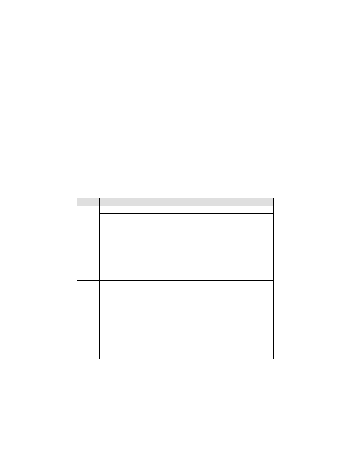
LED Indicators
LED
Color
Description
PWR 1,
PWR 2
Green
Power is on
Off
Power is off
Ready
Green
Steady on: Power is on, and the unit is functioning
normally
Blinking: The unit is responding to the software’s
Locate function
Red
Steady on: Power is on, and the unit is booting up
Blinking: Indicates an IP conflict, or the DHCP or
BOOTP server is not responding properly
Flashing quickly: the microSD card failed
LAN Green
(Flashing
only)
The Ethernet port is receiving or transmitting data
Modbus TCP Client:
Modbus communication in progress
Modbus TCP Server:
Modbus communication in progress
EtherNet/IP Adapter:
EtherNet/IP communication is exchanging data
PROFINET IO Device:
PROFINET communication is exchanging data
Page 3

- 3 -
LED
Color
Description
Red
(Flashing
only)
A communication error occurred
Modbus TCP Client:
1. Received an exception code or framing error
(parity error, checksum error)
2. Command timeout (slave device is not
responding)
3. TCP connection timeout
Modbus TCP Server:
1. Received an invalid function code or framing
error
(parity error, checksum error)
2. Accessed invalid register address or coil address
EtherNet/IP Adapter:
The connection was refused due to incorrect
configuration
Off
No communication
MB*
Green
(Flashing
only)
Modbus is receiving or transmitting data
Red
(Flashing
only)
A communication error occurred
Master Mode:
1. Received an exception code or framing error
(parity error, checksum error)
2. Command timeout (the slave device is not
responding)
Slave Mode:
1. Received an invalid function code or framing
error
(parity error, checksum error)
2. Accessed invalid register address or coil address
Off
No communication
PBS
Green
(Flashing
only)
PROFIBUS is receiving or transmitting data
Red
(Steady)
Error in the configuration or parameter data.
Off
PROFIBUS offline or Slave ID is wrong.
Eth1,
Eth2
Green
Indicates an 100 Mbps Ethernet connection
Amber
Indicates a 10 Mbps Ethernet connection
Off
The Ethernet cable is disconnected
*Only indicates serial communication status; for Modbus TCP status,
please refer to LAN LED indicator.
Page 4

- 4 -
Dimensions
Unit = mm (inch)
Reset Button
Restore the MGate to factory default settings by using a pointed object
(such as a straightened paper clip) to hold the reset button down until the
Ready LED stops blinking (approximately five seconds).
Pull-Up, Pull-Down, and Terminator for RS-485 (Modbus)
On the MGate 5111’s left side panel, you will find DIP
switches to adjust each serial port’s pull
-up resistor,
pull
-down resistor, and terminator.
SW
MODBUS
1 2 3
Pull-up
resistor
Pull-down
resistor
Terminator
ON
1 kΩ
1 kΩ
120 Ω
OFF
150 kΩ
(default)
150 kΩ
(default)
– (default)
Rotary Switch
Before communicating, you must assign a slave ID to the
PROFIBUS slave, If you would like to assign an address
between 0 to 99, you need to change the rotary switch to
the desired address. If you would like to assign an
address which is over 99, you must s
et it via web
console.
Page 5

- 5 -
Hardware Installation Procedure
1. Connect the power adapter. Connect the 12-48 VDC power line or
DIN-rail power supply to the MGate 5111’s terminal block.
2. Use a PROFIBUS cable to connect the MGate to a PROFIBUS PLC or
other PROFIBUS master.
3. Use an Ethernet cable to connect the MGate to the Modbus TCP client,
Modbus TCP server device, PROFINET IO controller, or EtherNet/IP
scanner device.
4. The MGate 5111 is designed to be attached to a DIN rail or mounted
on a wall. For DIN-rail mounting, push down the spring and properly
attach it to the DIN rail until it “snaps” into place. For wall mounting,
install the wall-mount kit (optional) first and then screw the device
onto the wall. The following figure illustrates the two mounting
options:
Software Installation Information
Please download the user's manual and DSU (Device Search Utility) from
Moxa’s website: www.moxa.com
. Insert the CD and follow the on-screen
instructions. Please refer to the User’s Manual for additional details on
using the Device Search Utility.
The MGate 5111 also supports login via a web browser.
Default IP address: 192.168.127.254
Default account: admin
Default password: moxa
Pin Assignments
Ethernet Port (RJ45)
Pin
Signal
1
Tx+
2
Tx-
3
Rx+
6
Rx-
Page 6

- 6 -
Modbus Serial Port (Male DB9)
Pin RS-232
RS-422/
RS-485 (4W)
RS-485 (2W)
1
DCD
TxD-(A)
–
2
RXD
TxD+(B)
–
3
TXD
RxD+(B)
Data+(B)
4
DTR
RxD-(A)
Data-(A)
5*
GND
GND
GND
6
DSR – –
7
RTS – –
8
CTS – –
9 – –
–
*Signal ground
PROFIBUS Serial Port (Female DB9)
Pin
Signal
1 - 2 - 3
PROFIBUS D+
4
RTS
5
Signal common
6
5V 7 -
8
PROFIBUS D-
9
-
Console Port (RS-232)
The MGate 5111 Series can use an RJ45 serial port to connect to a PC to
configure the device.
Pin
Signal
1
DSR
2
RTS
3
GND
4
TXD
5
RXD
6
DCD
7
CTS
8
DTR
Power Input and Relay Output Pinouts
V2+ V2-
V1+ V1-
Shielded
Ground
DC
Power
Input 2
DC
Power
Input 2
N.O. Common N.C.
DC
Power
Input 1
DC
Power
Input 1
Page 7

- 7 -
Specifications
Power Requirements
Power Input
12 to 48 VDC
Power Consumption
416mA@12VDC, 195mA@24VDC,
110mA@48VDC
Operating Temperature
Standard model:
0 to 60°C (32 to 140°F)
Wide temperature model:
-40 to 75°C (-40 to 167°F)
Ambient Relative Humidity
5 to 95% RH
Dimensions
45.8 x 105 x 134 mm (1.80 x 4.13 x 5.28 in)
Reliability
Alert Tools
Built-in buzzer and RTC
MTBF
718,131 hrs
1. DEMKO Certificate number: 17 ATEX 1848X
IECEx Certificate number: IECEx UL 17.0019X
2. Ambient Temperature Range:
0°C to 60°C (for models without suffix –T)
-40°C to 75°C (for models with suffix –T only)
3. Certification String: Ex nA nC IIC T4 Gc
4. Standards Covered: EN 60079-0:2012+A11:2013/IEC 60079-0 6th
Ed. AND EN 60079-15:2010/IEC 60079-15 4th Ed.
5. The conditions of safe use:
a. Ethernet Communications Devices are intended for mounting in a
tool-accessible IP54 enclosure and use in an area of not more
than pollution degree 2 as defined by IEC/EN 60664-1.
b. Conductors suitable for use in an ambient temperature greater
than 86°C must be used for the power supply terminal.
c. A 4 mm
2
conductor must be used when a connection to the
external grounding screw is utilized.
d. Provisions shall be made, either in the equipment or external to
the equipment, to prevent the rated voltage from being exceeded
by the transient disturbances of more than 140% of the
peak-rated voltage.
When wiring the relay contact (R), digital input (DI), and power inputs
(P1/P2), we suggest using AWG (American Wire Gauge) 16-24 as a cable
and the corresponding pin-type cable terminals. The connector can
withstand a maximum torque of 5 pound-inches. The wire temperature
rating should be at least 105°C.
ATTENTION
For installations in hazardous locations (Class 1, Division 2):
These devices are to be installed in an enclosure with a
tool-removable cover or door, suitable for the environment.
Page 8

- 8 -
NOTE
This equipment is suitable for use in Class 1, Division 2, Groups A,
B, C, D or nonhazardous locations only
WARNING
EXPLOSION HAZARD
Do not disconnect the equipment unless the power has been
switched off, or the area is known to be nonhazardous.
WARNING
EXPLOSION HAZARD
The substitution of any components may impair suitability for
Class 1, Division 2.
WARNING
EXPOSURE TO SOME CHEMICALS MAY DEGRADE THE
SEALING
PROPERTIES OF MATERIALS USED IN THE FOLLOWING DEVICE:
Sealed Relay Device U21.
WARNING
EXPLOTION HAZARD
Indoor use and Pollution degree 2.
WARNING
EXPLOTION HAZARD
The equipment and label must be wiped by a dry cloth.
WARNING
EXPLOTION HAZARD
The device may only be connected to the supply voltage
connections
compliant with UL60950, or UL61010-1, or
UL61010-2-201 Safety Extra-Low Voltages (SELV).
Moxa Inc.
Fl. 4, No. 135, Lane 235, Baoqiao Rd.
Xindian Dist., New Taipei City, 23145
Taiwan, R.O.C.
 Loading...