

Page 1

MGate 5109 User’s Manual
Edition 2.2, March 2018
www.moxa.com/product
© 2018 Moxa Inc. All rights reserved.
Page 2

MGate 5109 User’s Manual
The software described in this manual is furnished under a license agreement and may be used only in accordance with
the terms of that agreement.
Copyright Notice
© 2018 Moxa Inc. All rights reserved.
Trademarks
The MOXA logo is a registered trademark of Moxa Inc.
All other trademarks or registered marks in this manual belong to their respective manufacturers.
Disclaimer
Information in this document is subject to change without notice and does not represent a commitment on the part of
Moxa.
Moxa provides this document as is, without warranty of any kind, either expressed or implied, including, but not limited
to, its particular purpose. Moxa reserves the right to make improvements and/or changes to this manual, or to the
products and/or the programs described in this manual, at any time.
Information provided in this manual is intended to be accurate and reliable. However, Moxa assumes no responsibility for
its use, or for any infringements on the rights of third parties that may result from its use.
This product might include unintentional technical or typographical errors. Changes are periodically made to the
information herein to correct such errors, and these changes are incorporated into new editions of the publication.
Technical Support Contact Information
www.moxa.com/support
Moxa Americas
Toll
-free: 1-888-669-2872
Tel:
+1-714-528-6777
Fax:
+1-714-528-6778
Moxa Chi
na (Shanghai office)
Toll
-free: 800-820-5036
Tel:
+86-21-5258-9955
Fax:
+86-21-5258-5505
Moxa Europe
Tel:
+49-89-3 70 03 99-0
Fax: +49-89-3 70 03 99-99
Moxa Asia
-Pacific
Tel:
+886-2-8919-1230
Fax: +886-2-8919-1231
Moxa India
Tel:
+91-80-4172-9088
Fax:
+91-80-4132-1045
Page 3

Table of Contents
1. Introduction ...................................................................................................................................... 1-1
Overview ........................................................................................................................................... 1-2
Package Checklist ............................................................................................................................... 1-2
Product Features ................................................................................................................................ 1-2
2. Hardware .......................................................................................................................................... 2-1
Power Input and Relay Output Pinouts................................................................................................... 2-2
LED Indicators .................................................................................................................................... 2-2
Dimensions ........................................................................................................................................ 2-3
Pin Assignments ................................................................................................................................. 2-3
Mounting the Unit ............................................................................................................................... 2-4
Specifications ..................................................................................................................................... 2-5
Reset Button ...................................................................................................................................... 2-7
Pull-high, Pull-low, and Terminator for RS-485 ....................................................................................... 2-7
MicroSD ............................................................................................................................................. 2-8
3. Getting Started.................................................................................................................................. 3-1
Connecting the Power ......................................................................................................................... 3-2
Connecting Serial Devices .................................................................................................................... 3-2
Connecting to a Network ..................................................................................................................... 3-2
Installing DSU Software ....................................................................................................................... 3-2
Logging in to the Web Console ............................................................................................................. 3-3
Quick Setup ....................................................................................................................................... 3-4
Quick Setup—System Setting ........................................................................................................ 3-4
Quick Setup—Select Protocol ........................................................................................................ 3-5
4. Web Console Configuration and Troubleshooting .............................................................................. 4-1
Overview ........................................................................................................................................... 4-2
Basic Settings .................................................................................................................................... 4-2
Network Settings ................................................................................................................................ 4-3
Serial Settings .................................................................................................................................... 4-3
Protocol Settings (Agent Mode) ............................................................................................................ 4-4
Protocol Settings—Protocol Conversion .......................................................................................... 4-5
Protocol Settings—Configure MGate’s Role 1 and Role 2 ................................................................... 4-6
Protocol Settings (Transparent Mode) .................................................................................................. 4-27
Modbus Transparent .................................................................................................................. 4-27
Protocol Settings—Modbus Transparent—Mode ............................................................................. 4-28
Protocol Settings—Modbus Transparent—Slave ID Map .................................................................. 4-29
Protocol Settings—Modbus Transparent—Priority Control ................................................................ 4-31
Protocol Settings—Modbus Transparent—Advanced Settings ........................................................... 4-31
DNP3 Transparent ..................................................................................................................... 4-32
Protocol Settings—DNP3 Transparent—Advanced Settings .............................................................. 4-34
System Management ......................................................................................................................... 4-34
System Management—Accessible IP List....................................................................................... 4-34
System Management—DoS Defense ............................................................................................ 4-35
System Management—System Log Settings .................................................................................. 4-35
System Management—Auto Warning Settings ............................................................................... 4-36
System Management—Email Alert ............................................................................................... 4-37
System Management—SNMP Trap ............................................................................................... 4-37
System Management—SNMP Agent ............................................................................................. 4-38
System Management—LLDP Settings ........................................................................................... 4-39
System Management—Certificate ................................................................................................ 4-39
System Management—Misc. Settings ........................................................................................... 4-40
System Management—Maintenance ............................................................................................. 4-42
System Monitoring (Troubleshooting) .................................................................................................. 4-44
System Monitoring—System Status ............................................................................................. 4-44
System Monitoring—Protocol Status............................................................................................. 4-45
Status Monitoring ............................................................................................................................. 4-50
5. Configuration (Text Mode Console) ................................................................................................... 5-1
6. Network Management Tool (MXstudio) ............................................................................................. 6-1
Overview ........................................................................................................................................... 6-2
Page 4

1
1. Introduction
Welcome to the MGate 5109 line of Modbus-to-DNP3 gateways. All models feature easy protocol conversion
between Modbus RTU/ASCII, Modbus TCP, and DNP3 protocols. This chapter is an introduction to the MGate
5109.
The following topics are covered in this chapter:
Overview
Package Checklist
Product Features
Page 5

MGate 5109 Introduction
1-2
Overview
The MGate 5109 is an industrial Ethernet gateway for Modbus RTU/ASCII/TCP and DNP3 serial/TCP/UDP
protocol conversion. All models are protected with a rugged metallic casing, DIN-rail mountable, and offer
built-in serial isolation. The rugged design is suitable for industrial applications such as oil/gas, power, process
automation, and factory automation.
Package Checklist
All models of the MGate 5109 series are shipped with the following items:
Standard Accessories:
• 1 MGate 5109 gateway
• 1 serial cable: DBL-RJ45F9-150
• Documentation and software CD
• Quick installation guide (printed)
• Warranty card
Please notify your sales representative if any of the above items are missing or damaged.
Optional Accessories (can be purchased separately)
• CBL-F9M9-150: DB9-female-to-DB9-male serial cable, 150 cm
• CBL-F9M9-20: DB9-female-to-DB9-male serial cable, 20 cm
• CBL-RJ45SF9-150: RJ45-to-DB9-female shielded serial cable, 150 cm
• ADP-RJ458P-DB9F: DB9-female-to-RJ45 connector
• ADP-RJ458P-DB9F-ABC01: DB9-female-to-RJ45 connector
• Mini DB9F-to-TB: DB9-female-to-terminal-block connector
Product Features
• Gateway function to transfer data between Modbus RTU/ASCII/TCP and DNP3 serial/TCP/UDP
• Support for both DNP3 master and outstation
• Up to 31 Modbus serial slaves or DNP3 serial outstations
• Up to 32 Modbus TCP slaves or DNP3 TCP/UDP outstations
• Support DNP 3.0 subset level 2
• DNP3 master mode support up to 18800 points
• Effortless configuration via Web console
• Complete packet analysis and diagnosis information for maintenance
• Redundant dual DC power inputs and relay output supported
• MicroSD card supported for configuration backup
• -40 to 75°C wide operating temperature range models available
• Serial port with 2 kV built-in isolation protection
• Built-in Ethernet cascading for easy wiring
Page 6

2
2. Hardware
The following topics are covered in this chapter:
Power Input and Relay Output Pinouts
LED Indicators
Dimensions
Pin Assignments
Mounting the Unit
Specifications
Reset Button
Pull-high, Pull-low, and Terminator for RS-485
MicroSD
Page 7
MGate 5109 Hardware
2-2
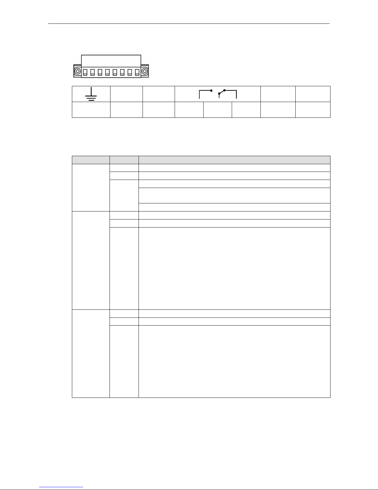
Power Input and Relay Output Pinouts
V2+ V2-
V1+ V1-
Shielded
Ground
DC Power
Input 2
DC Power
Input 2
N.O. Common N.C.
DC Power
Input 1
DC Power
Input 1
LED Indicators
Agent Mode:
LED Color Description
Ready Off Power is off or a fault condition exists
Green
Steady: Power is on, and the MGate is functioning normally
Red Steady: Power is on, and the MGate is booting up
Blinking slowly: Indicates an IP conflict, or the DHCP or BOOTP server is not
responding properly
Flashing quickly: microSD card failed
MB*
Off
No serial communication with Modbus device
Green Normal Modbus serial communication in progress
Red Serial communication error
When MGate 5109 acts as Modbus Master:
1. Slave device returned an error (exception)
2. Received frame error (parity error, checksum error)
3. Timeout (slave device no response)
When MGate 5109 acts as Modbus Slave:
1. Received invalid function code
2. Master accessed invalid register addresses or coil addresses
3. Received frame error (parity error, checksum error)
DNP3* Off No serial communication with DNP3 device
Green Normal DNP3 serial communication in progress
Red Serial communication error
When MGate 5109 acts as DNP3 Master:
1. Received outstation exception (format error, checksum error, invalid data,
outstation responds not support)
2. Timeout (outstation no response)
When MGate 5109 acts as DNP3 outstation:
1. Received master exception (format error, checksum error, invalid data)
2. Timeout (master no response)
*Only indicates serial communication status; for Ethernet status, refer to the LED indicator on the Ethernet
port.
Page 8
MGate 5109 Hardware
2-3
Transparent Mode:
LED Color Description
Ready Off Power is off, or a fault condition exists
Green Steady: Power is on, and the MGate is functioning normally
Red Steady: Power is on, and the MGate is booting up
Blinking slowly: Indicates an IP conflict, or the DHCP or BOOTP server is not
responding properly
Flashing quickly: microSD card failed
MB Off No communication with Modbus device
Green Modbus communication in progress**
DNP3 Off No communication with DNP3 device
Green DNP3 communication in progress**
**The LED will light up (green) only during the period when the MGate is receiving data on a serial port (Rx);
this does not include transmitted data (Tx).
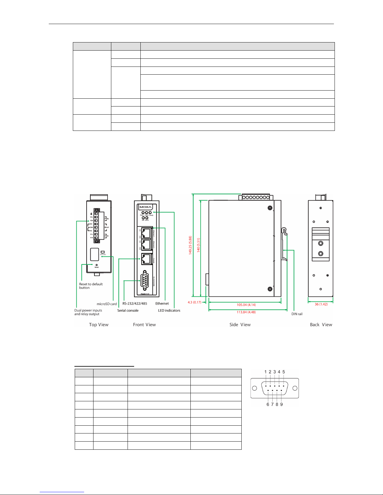
Dimensions
Unit: mm (inch)
Pin Assignments
Serial Port (Male DB9)
Pin RS-232 RS-422/RS-485 (4W) RS-485 (2W)
1 DCD TxD-(A) –
2
RXD
TxD+(B)
–
3 TXD RxD+(B) Data+(B)
4 DTR RxD-(A) Data-(A)
5* GND GND GND
6 DSR – –
7 RTS – –
8 CTS – –
9 – – –
*Signal ground
Page 9
MGate 5109 Hardware
2-4
Ethernet Port (RJ45)
Pin Signal
1 Tx+
2 Tx-
3 Rx+
6 Rx-
Console Port (RS-232)
The MGate 5109 series can use an RJ45 serial port to connect to a PC for device configuration.
Pin RS-232
1 DSR
2 RTS
3 GND
4 TXD
5 RXD
6 DCD
7
CTS
8 DTR
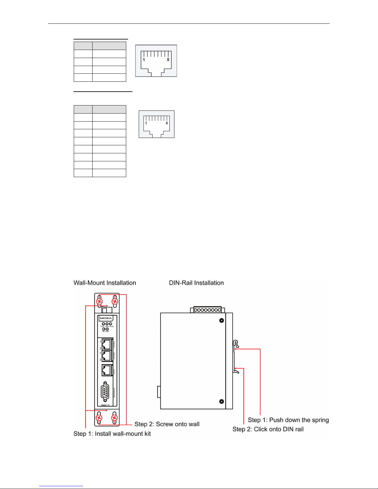
Mounting the Unit
1. Connect the power adapter. Connect the 12-48 VDC power line or DIN-rail power supply to the MGate
5109’s terminal block.
2. Use a serial cable to connect the MGate to the Modbus or DNP3 device.
3. Use an Ethernet cable to connect the MGate to the Modbus or DNP3 device.
4. The MGate 5109 is designed to be attached to a DIN rail or mounted on a wall. For DIN-rail mounting, push
down the spring and properly attach it to the DIN rail until it snaps into place. For wall mounting, install the
wall-mounting kit (optional) first and then screw the device onto the wall.
The following figure illustrates the two mounting options:
Page 10

MGate 5109 Hardware
2-5
Specifications
Ethernet Interface
Protocols:
Modbus TCP client/server, DNP 3.0 TCP/UDP master/outstation
Number of Ports:
2 (1 IP, Ethernet cascade)
Speed:
10/100 Mbps, Auto MDI/MDIX
Connector:
8-pin RJ45
Magnetic Isolation Protection:
1.5 kV (built-in)
Serial Interface
Protocols:
Modbus RTU/ASCII master/slave, DNP 3.0 serial master/outstation
Number of Ports:
1
Serial Standards: RS-232/422/485, software selectable
Connectors:
DB9 male
RS
-485 Data Direction Control: ADDC® (automatic data direction control)
Pull High/Low Resistor for RS
-485: 1 kΩ, 150 kΩ
Terminator for RS
-485: 120 Ω
Isolation:
2 kV (built-in)
Serial Communication Parameters
Data Bits:
7, 8
Stop Bits:
1, 2
Parity:
None, Even, Odd, Space, Mark
Flow Control:
RTS/CTS, RTS Toggle (RS-232 only)
Baudrate:
50 bps to 921.6 kbps
Serial Signals
RS
-232: TxD, RxD, RTS, CTS, DTR, DSR, DCD, GND
RS
-422: Tx+, Tx-, Rx+, Rx-, GND
RS
-485-4w: Tx+, Tx-, Rx+, Rx-, GND
RS-485-2w: Data+, Data-, GND
Modbus
Functions Supported:
1, 2, 3, 4, 5, 6, 15, 16, 23
Max. No. of Commands:
100
Max. No. of Connections:
MGate
as Modbus TCP Master: 32 slave connections
MGate as Modbus TCP slave: 16 master connections
Page 11

MGate 5109 Hardware
2-6
DNP3
Max. No. of Connections:
• Transparent mode:
16 DNP3 TCP master connections or 32 DNP3 TCP outstation connections
• Agent mode:
MGate as DNP3 TCP/UDP master: 32 outstation connections
MGate as DNP3 TCP/UDP outstation: 1 master connection
DNP3 Internal Database:
• For each outstation:
Binary Inputs: 256 points
Analog Inputs: 64 points
Counters: 64 points
Binary Outputs: 256 points
Analog Outputs: 64 points
• When the MGate 5109 is configured as a DNP3 outstation
Binary Inputs: 8192 points
Counters: 2048 points
Binary Outputs: 8192 points
Analog Outputs: 2048 points
Binary Input Events: 1024
Analog Input Events: 1024
Counter Events: 1024
Software
Configuration Options:
Web Console, Serial Console Utility
Configuration:
MXconfig, MXview, SNMP (v1, v2c, v3), Private MIB
Physical Characteristics
Housing:
Metal, IP30
Weight:
507 g (1.12 lb)
Dimensions:
36 x 105 x 140 mm (1.42 x 4.14 x 5.51 in)
Storage Card Slot:
1 microSD (SDHC) card slot supports up to 32 GB
Relay Alarm Circuit:
3-pin circuit with current carrying capacity of 2 A @ 30 VDC
Environmental Limits
Operating Temperature:
Standard Models: 0 to 60°C (32 to 140°F)
Wide Temp. Models:
-40 to 75°C (-40 to 167°F)
Storage Temperature:
-40 to 85°C (-40 to 185°F)
Ambient Relative Humidity:
5 to 95% (non-condensing)
Vibration: IEC 60068-2-6, IEC 60068-2-64
Shock:
IEC 60068-2-27
Drop:
IEC 60068-2-32
Power Requirements
Input Voltage:
12 to 48 VDC
Input Current:
455 mA max., Class 2
Power Connector:
Terminal block
Page 12
MGate 5109 Hardware
2-7
Standards and Certifications
Safety:
UL 508, EN 60950-1
Hazardous Location:
Class 1 Division 2, ATEX, IECEx
EMC:
EN 55022/24
EMI:
CISPR 22, FCC Part 15B Class B
EMS:
IEC 61000
-4-2 ESD: Contact: 8 kV; Air: 15 kV
IEC 61000
-4-3 RS: 80 MHz to 1 GHz: 10 V/m
IEC 61000
-4-4 EFT: Power: 4 kV; Signal: 2 kV
IEC 61000
-4-5 Surge: Power: 2 kV; Signal: 2 kV
IEC 61000
-4-6 CS: 150 kHz to 80 MHz: 10 V/m
IEC 61000
-4-8 PFMF
MTBF (mean time between failures)
Time:
859,422 hrs
Standard:
Telcordia SR332
Warranty
Warranty Period:
5 years
Details:
See www.moxa.com/warranty
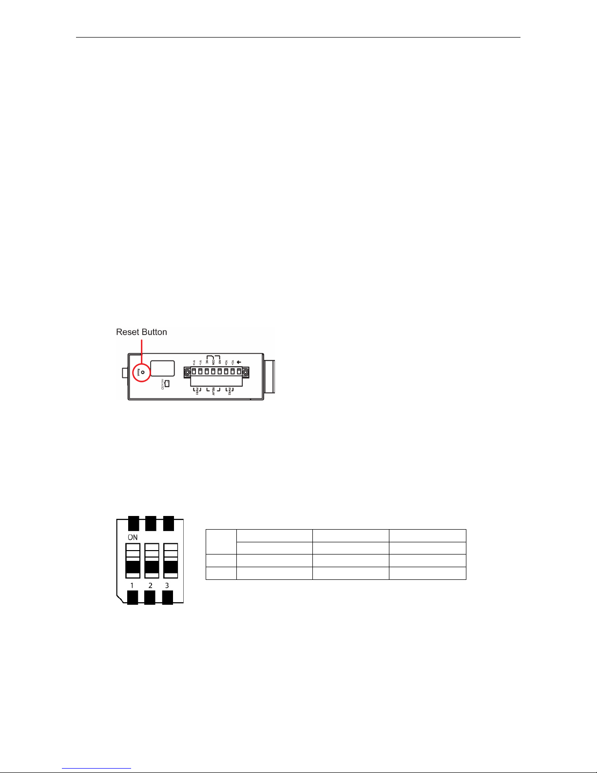
Reset Button
Restore the MGate to factory default settings by using a pointed object (such as a straightened paper clip) to
hold the reset button down until the Ready LED stops blinking (approx. five seconds).
Pull-high, Pull-low, and Terminator for RS-485
Remove the MGate 5109’s top cover, and you will find DIP switches to adjust each serial port’s pull-high resistor,
pull-low resistor, and terminator.
SW
1 2 3
Pull-high resistor Pull-low resistor Terminator
ON 1 kΩ 1 kΩ 120 Ω
OFF 150 kΩ* 150 kΩ* –*
*Default
Page 13

MGate 5109 Hardware
2-8
MicroSD
The MGate 5109 provides users with an easy way to backup, copy, replace, or deploy. The MGate is equipped
with a microSD card slot. Users can plug in a microSD card to backup data, including the system configuration
setting, and system data log.
First time using the MGate gateway with a new microSD card
1. Format the microSD card as FAT file system through a PC.
2. Power off the MGate and insert the microSD card (ensure that the microSD card is empty).
3. Power on the MGate. The default settings will be copied to the microSD card.
4. Manually configure the MGate via web console, and all the stored changes will copy to the microSD card for
synchronization.
First time using the MGate with a microSD card containing a configuration file
1. Power off the MGate and insert the microSD card.
2. Power on the MGate.
3. The configuration file stored in the microSD card will automatically copy to the MGate.
Duplicating current configurations to another MGate gateway
1. Power off the MGate and insert a new microSD card.
2. Power on the MGate.
3. The configuration will be copied from the MGate to the microSD card.
4. Power off the MGate and insert the microSD card to the other MGate.
5. Power on the second MGate.
6. The configuration file stored in the microSD card will automatically copy to the MGate.
Malfunctioning MGate replacement
1. Replace the malfunctioning MGate with a new MGate.
2. Insert the microSD card into the new MGate.
3. Power on the MGate.
4. The configuration file stored on the microSD card will automatically copy to the MGate.
MicroSD card writing failure
The following circumstances may cause the microSD card to experience a writing failure:
1. The microSD card has less than 20 Mbytes of free space remaining.
2. The microSD card is write-protected.
3. The file system is corrupted.
4. The microSD card is damaged.
The MGate will stop working in case of the above events, accompanied by a flashing Ready LED and beeping
alarm. When you replace the MGate gateway’s microSD card, the microSD card will synchronize the
configurations stored on the MGate gateway. Note that the replacement microSD card should not contain any
configuration files on it; otherwise, the out-of-date configuration will copy to the MGate device.
Page 14

3
3. Getting Started
The following topics are covered in this chapter:
Connecting the Power
Connecting Serial Devices
Connecting to a Network
Installing DSU Software
Logging in to the Web Console
Quick Setup
Quick Setup—System Setting
Quick Setup—Select Protocol
Page 15

MGate 5109 Getting Started
3-2
Connecting the Power
The unit can be powered by connecting a power source to the terminal block:
1. Loosen or remove the screws on the terminal block.
2. Turn off the power source and then connect a 12–48 VDC power line to the terminal block.
3. Tighten the connections, using the screws on the terminal block.
4. Turn on the power source.
Note that the unit does not have an on/off switch. It automatically turns on when it receives power. The PWR
LED on the top panel will glow to indicate that the unit is receiving power. For power terminal block pin
assignments, refer to the Power Input and Relay Output Pinout section in chapter 2.
Connecting Serial Devices
MGate 5109 support Modbus serial and DNP3 serial devices. Before connecting or removing the serial
connection, first make sure the power is turned off. For the serial port pin assignments, see the Pin
Assignments section in chapter 2.
Connecting to a Network
Connect one end of the Ethernet cable to the MGate’s 10/100M Ethernet port and the other end of the cable to
the Ethernet network. The MGate will indicate a valid connection to the Ethernet in the following ways:
• The Ethernet LED maintains a solid green color when connected to a 100 Mbps Ethernet network.
• The Ethernet LED maintains a solid orange color when connected to a 10 Mbps Ethernet network.
• The Ethernet LED will flash when Ethernet packets are being transmitted or received.
Installing DSU Software
If you do not know the MGate gateway’s IP address when setting it up for the first time (default IP is
192.168.127.254); use an Ethernet cable to connect the host PC and MGate gateway directly. If you connect
the gateway and host PC through the same Ethernet switch, make sure there is no router between them. You
can then use Device Search Utility to detect the MGate gateways on your network.
The following instructions explain how to install the Device Search Utility (DSU), a utility to search for MGate
5109 units on a network.
1. Insert the Document and Software CD into the CD-ROM drive. Locate and run the following setup program
to begin the installation process:
dsu_setup_[Version]_Build_[DateTime].exe
The latest version might be named dsu_setup_Ver2.0_Build_xxxxxxxx.exe, for example:
2. You will be greeted by the Welcome window. Click Next to continue.
3. When the Select Destination Location window appears, click Next to continue. You may change the
destination directory by first clicking on Browse....
4. When the Select Additional Tasks window appears, click Next to continue. You may select Create a
desktop icon if you would like a shortcut to the DSU on your desktop.
5. Click Install to start copying the software files.
6. A progress bar will appear. The procedure should take only a few seconds to complete.
7. A message will indicate that the DSU is successfully installed. You may choose to run it immediately by
selecting Launch DSU.
8. You may also open the DSU through Start Programs MOXA DSU.
Page 16
MGate 5109 Getting Started
3-3
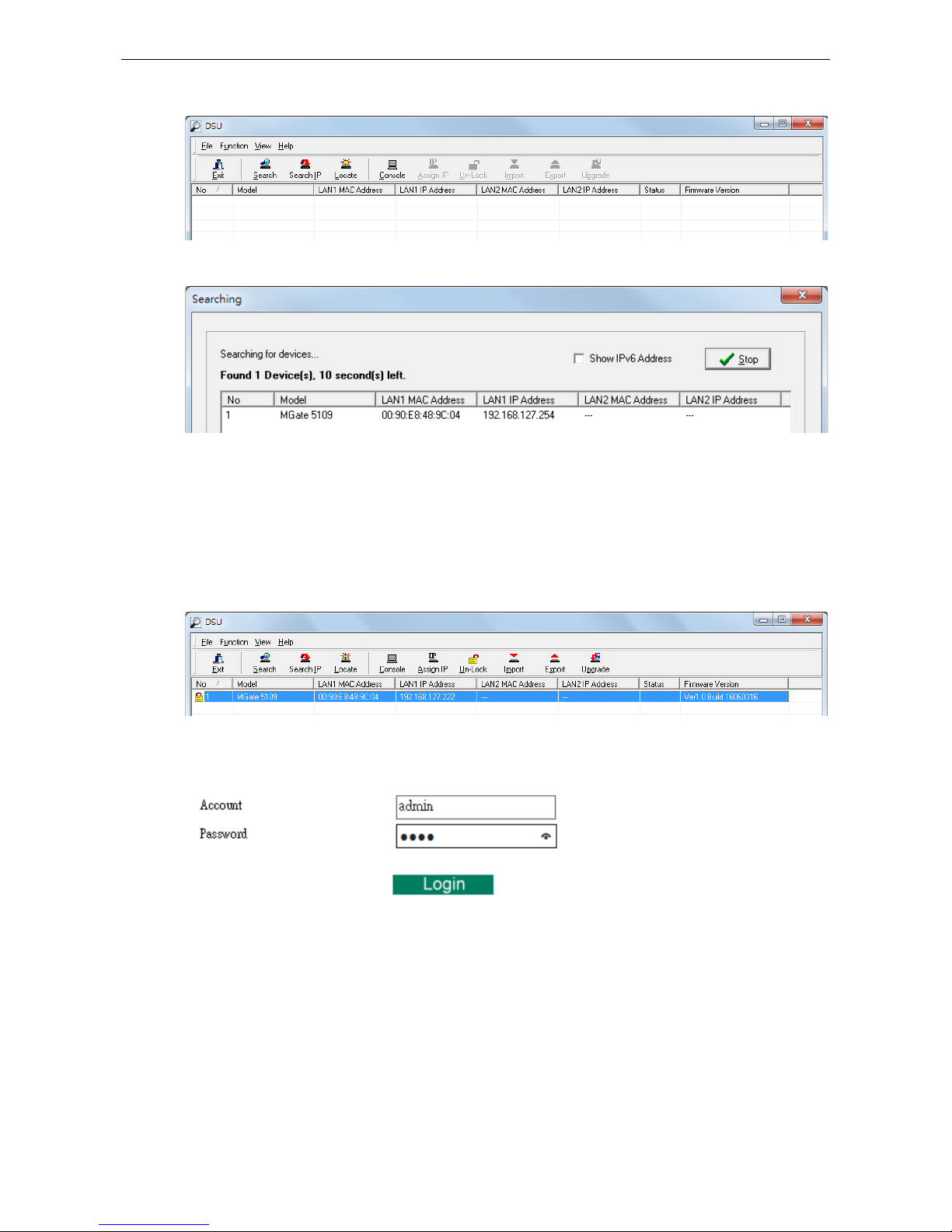
The DSU window should appear as shown below.
Click Search and a new Search window will pop up.
Logging in to the Web Console
Use the Web console to configure the MGate through Ethernet or verify the MGate’s status. Use a web browser,
such as Microsoft Internet Explorer or Google Chrome to connect to the MGate, using the HTTP/HTTPS protocol.
When the MGate gateway appears on the DSU device list, select the gateway and use the right-click the mouse
button to open a web console to configure the gateway.
On the first page of the web console, enter the
admin for the default Account name and moxa for the default
Password.
Page 17
MGate 5109 Getting Started
3-4
Quick Setup
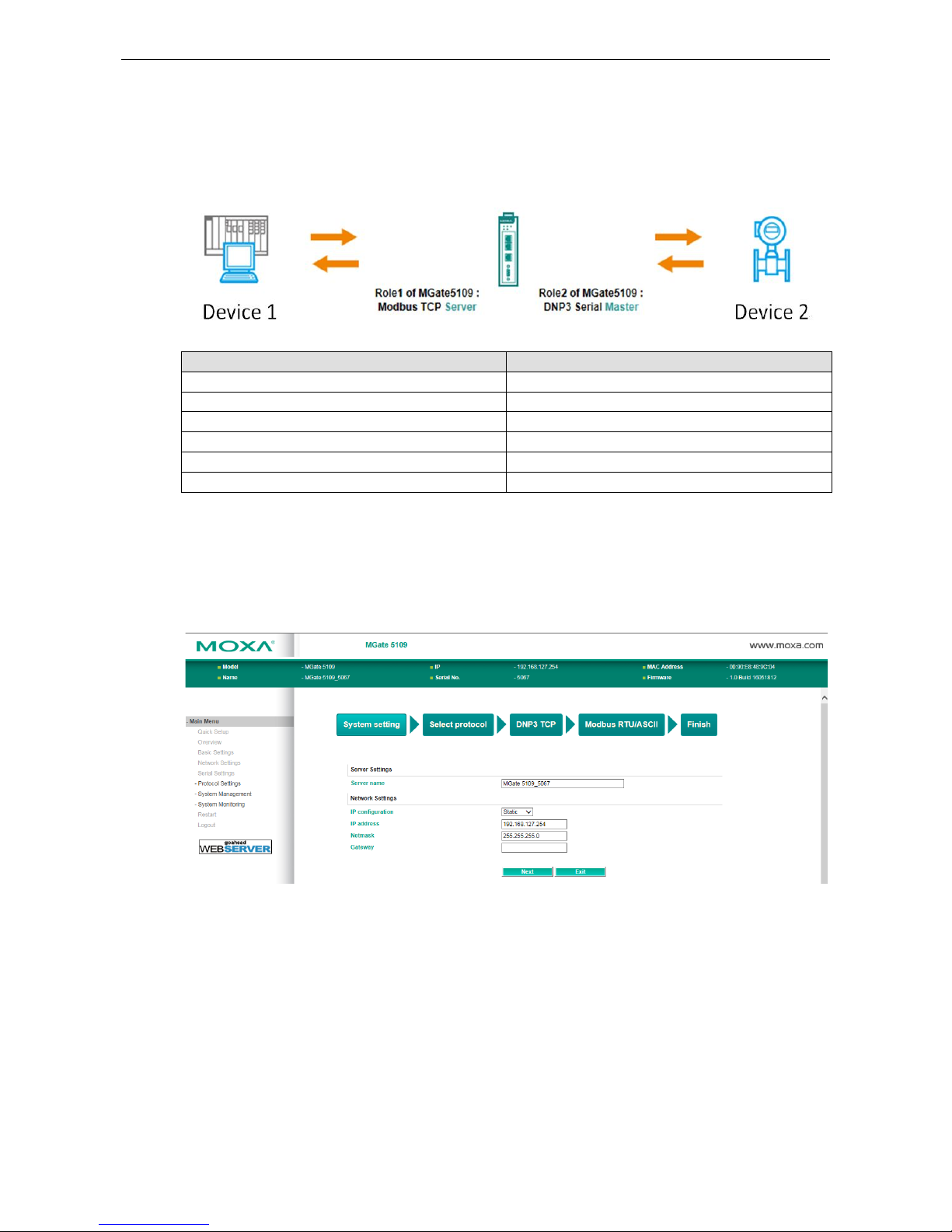
The MGate series now provides a Quick Setup wizard, an illustrated guide specifically designed to make the
configuration process easy. The Quick Setup wizard takes you through the configuration process from start to
finish so that you do not miss any step. The following agent modes are supported in the Quick Setup:
Device 1 Device 2
MB RTU/ASCII Master DNP3 TCP Outstation
MB TCP Client DNP3 serial Outstation
MB TCP Client DNP3 TCP/UDP Outstation
DNP3 serial Master MB TCP server
DNP3 TCP/UDP Master MB RTU/ASCII slave
DNP3 TCP/UDP Master MB TCP slave
Except for above agent modes, other combinations can be configured in Protocol Settings > Protocol
Conversion. For more information, refer to chapter 4.
Quick Setup—System Setting
First, configure the Server Settings to identify the units and Network Settings of the MGate.
Page 18
MGate 5109 Getting Started
3-5
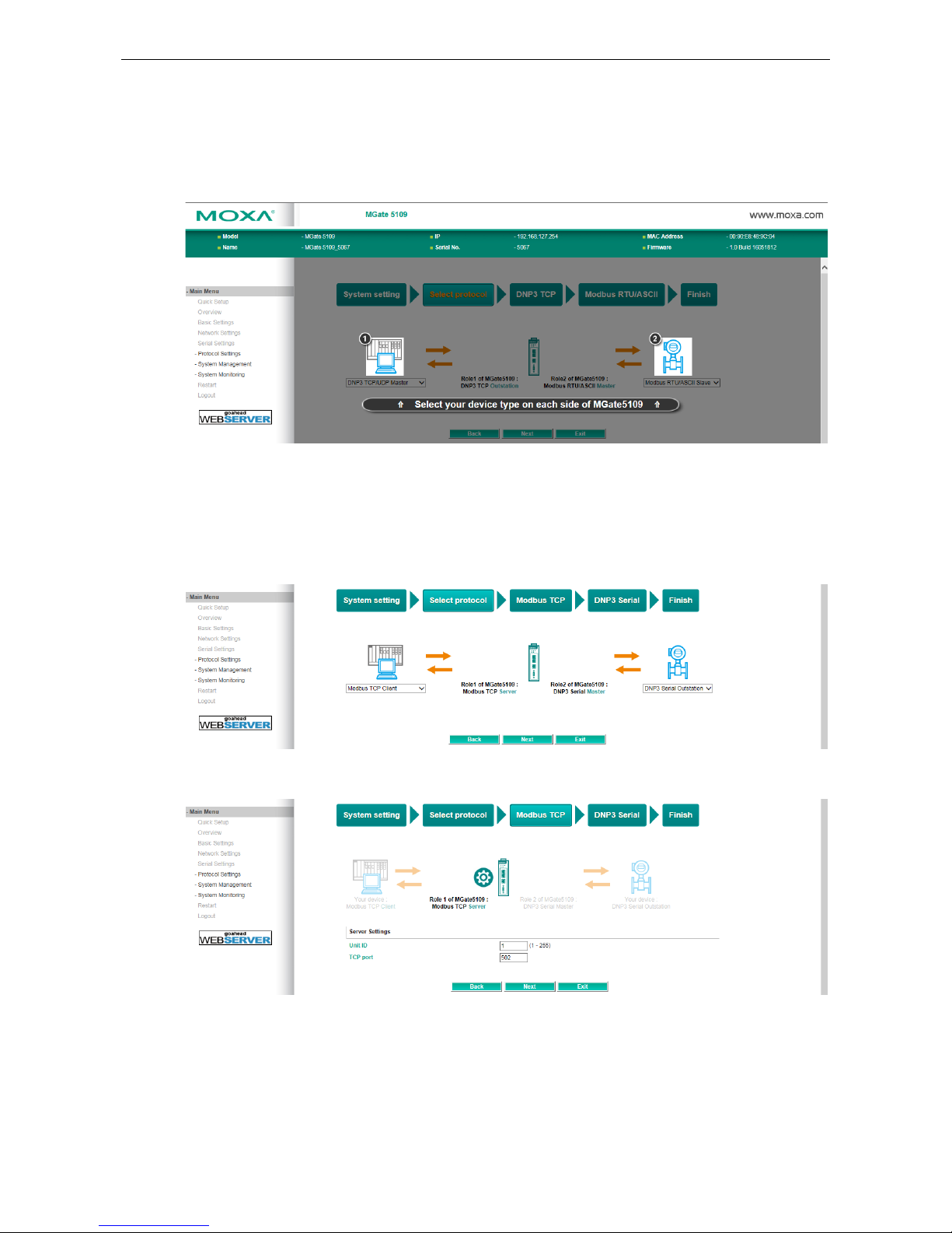
Quick Setup—Select Protocol
Then, you should select your devices' protocols on each side. After selection, MGate will change its role to the
correct one. For example, if the device is set as a DNP3 TCP/UDP Master, MGate will then automatically
configure as a DNP3 TCP/UDP Outstation by itself. Regarding protocol configuration, refer to chapter 4.
Quick Setup—Role 1 and Role 2 of MGate 5109 (Example 1)
After finishing the device protocol selection, Role 1 and Role 2 of MGate will be confirmed. You will need to
configure the roles on each side by the following steps. Here is an example of Role 1 as a Modbus TCP Server,
and Role 2 as a DNP3 Serial Master.
Modbus TCP settings: Set MGate Unit ID and TCP port.
Page 19

MGate 5109 Getting Started
3-6
DNP3 serial settings: Set MGate DNP3 Master ID address.
DNP3 serial settings: Add DNP3 Outstation List. For configuration details, refer to chapter 4.
Quick Setup—Finish (Example 1)
Once all the configurations are done, you can check if the parameters are correct on this webpage. Click Save
to make the parameters effective. To view DNP3 mapping data go to the Protocol Settings > I/O Data
Mapping page. For additional details, refer to chapter 4, Protocol Settings—I/O Data Mapping.
Page 20
MGate 5109 Getting Started
3-7
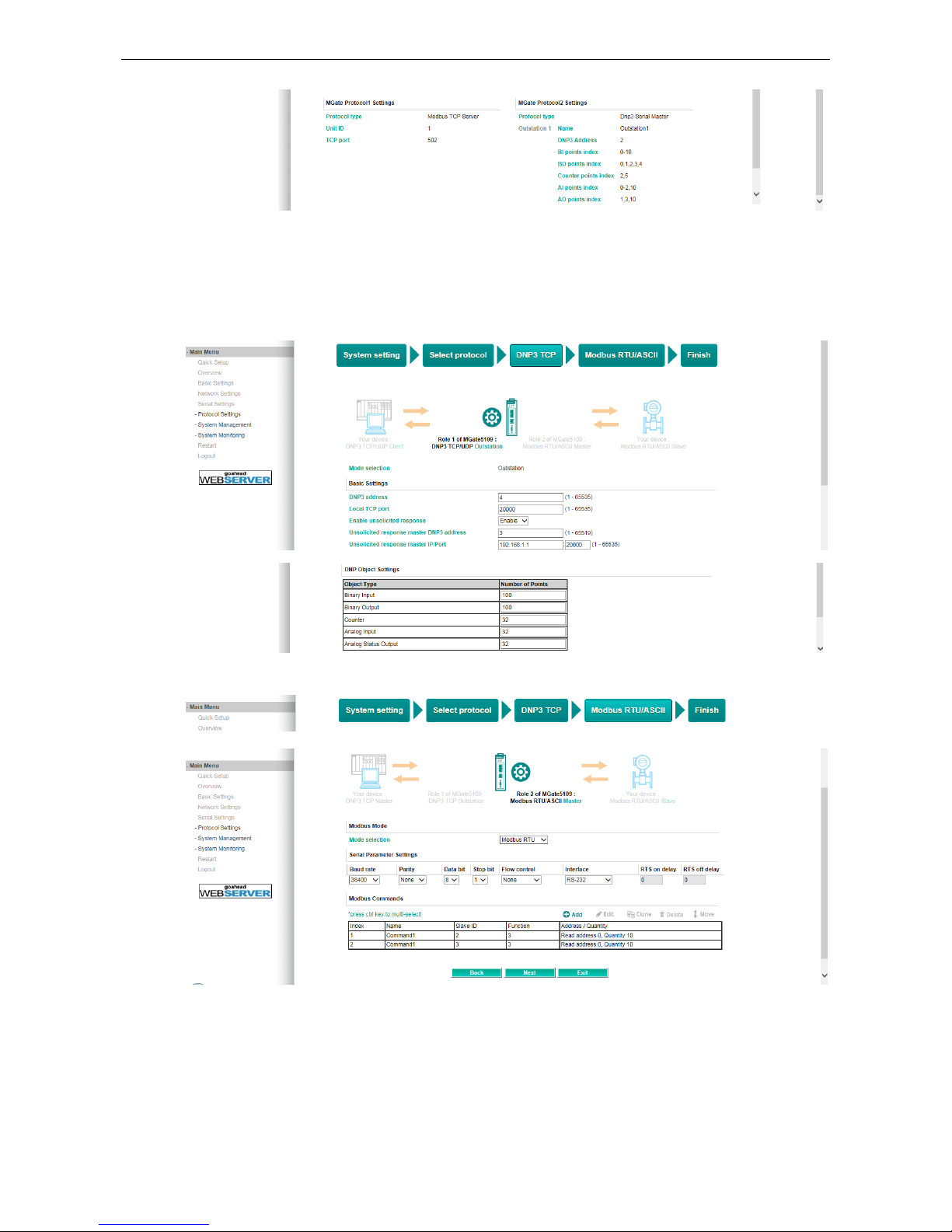
Quick Setup—Role 1 and Role 2 of MGate 5109 (Example 2)
Here is an example of Role 1 as a DNP3 TCP/UDP Outstation, and Role 2 as a Modbus RTU/ASCII Master.
DNP3 TCP settings: For configuration details, refer to chapter 4.
Modbus RTU/ASCII settings: For configuration details, refer to chapter 4.
Page 21
MGate 5109 Getting Started
3-8
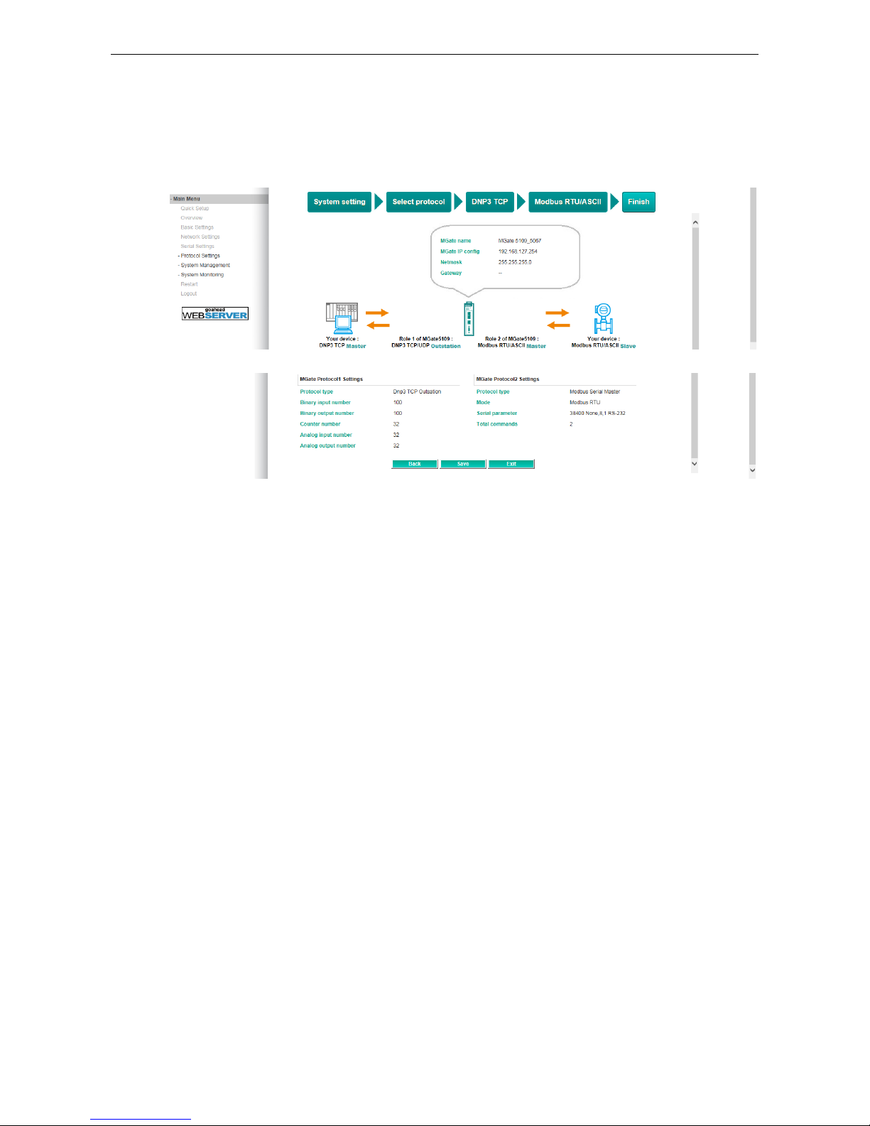
Quick Setup—Finish (Example 2)
Once all the configurations are done, you can check if all the parameters are correct on this webpage. Moreover,
if you want to determine the data mapping status, you can click the View I/O data mapping to know more
details. If all of them are correct, press Save to make the parameters effective.
Page 22

4
4. Web Console Configuration and
Troubleshooting
This chapter provides a quick overview of how to configure the MGate 5109 by web console.
The following topics are covered in this chapter:
Overview
Basic Settings
Network Settings
Serial Settings
Protocol Settings (Agent Mode)
Protocol Settings—Protocol Conversion
Protocol Settings—Configure MGate’s Role 1 and Role 2
Protocol Settings (Transparent Mode)
Modbus Transparent
Protocol Settings—Modbus Transparent—Mode
Protocol Settings—Modbus Transparent—Slave ID Map
Protocol Settings—Modbus Transparent—Priority Control
Protocol Settings—Modbus Transparent—Advanced Settings
DNP3 Transparent
Protocol Settings—DNP3 Transparent—Advanced Settings
System Management
System Management—Accessible IP List
System Management—DoS Defense
System Management—System Log Settings
System Management—Auto Warning Settings
System Management—Email Alert
System Management—SNMP Trap
System Management—SNMP Agent
System Management—LLDP Settings
System Management—Certificate
System Management—Misc. Settings
System Management—Maintenance
System Monitoring (Troubleshooting)
System Monitoring—System Status
System Monitoring—Protocol Status
Status Monitoring
Page 23
MGate 5109 Web Console Configuration and Troubleshooting
4-2
Overview
This section gives an overview of the MGate 5109 hardware.
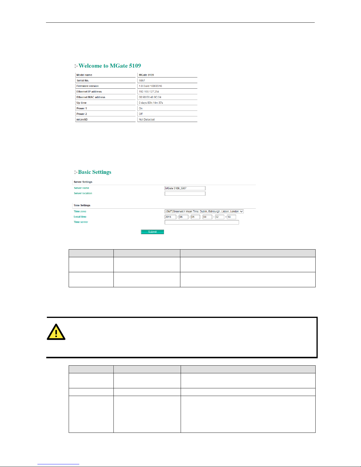
Basic Settings
On this webpage, you can change the name of the device and time zone settings.
Server Setting
Parameter Value Description
Server Name (an alphanumeric string)
You can enter a name to help you identify the unit, such as
the function, etc.
Server Location (an alphanumeric string)
You can enter a name to help you identify the unit location.
Such as “Cabinet A001.”
Time Settings
The MGate 5109 has a built-in Real-Time Clock for time calibration functions. Functions such as the log function
can add real-time information to the message.
ATTENTION
First-time users should select the time zone first. The console will display the “real time” according to the time
zone relative to GMT. If you would like to modify the real
-time clock, select Local time.
MGate’s firmware will
modify the GMT time according to the Time Zone.
Parameter Value Description
Time Zone User’s selectable time zone This field shows the currently selected time zone and allows
you to select a different time zone.
Local Time User’s adjustable time. (1900/1/1-2037/12/31)
Time Server IP or Domain address
(e.g., 192.168.1.1 or
time.stdtime.gov.tw)
This optional field specifies your time server’s IP address or
domain name if a time server is used on your network. The
module supports SNTP (RFC-1769) for automatic time
calibration. The MGate will request time information from
the specified time server every 10 minutes.
Page 24

MGate 5109 Web Console Configuration and Troubleshooting
4-3
ATTENTION
If the dispersion
of the time server is higher than the client (MGate), the client
will not accept NTP messages
from the
time server. MGate's dispersion is 1 second. You must configure your time server
with a dispersion
value
lower than 1 sec for the NTP process to complete.
Network Settings
The Network Settings is where the unit’s network settings are configured. You can modify the IP Configuration,
IP Address, Netmask, Default Gateway, and DNS.
Parameter Value Description
IP Configuration Static IP, DHCP, BOOTP Select Static IP if you are using a fixed IP address. Select
one of the other options if the IP address is set dynamically.
IP Address 192.168.127.254
(or other 32-bit number)
The IP (Internet Protocol) address identifies the server on
the TCP/IP network.
Netmask 255.255.255.0
(or other 32-bit number)
This identifies the server as belonging to a Class A, B, or C
network.
Gateway 0.0.0.0
(or other 32-bit number)
This is the IP address of the router that provides network
access outside the server’s LAN.
DNS Server 1 0.0.0.0
(or other 32-bit number)
This is the IP address of the primary domain name server.
DNS Server 2 0.0.0.0
(or other 32-bit number)
This is the IP address of the secondary domain name server.
Serial Settings
The MGate 5109 serial interface supports RS-232, 2-wire RS-485, 4-wire RS-485, and RS-422 interfaces. You
must configure the baudrate, parity, data bits, and stop bits before using the serial interface with Modbus
RTU/ASCII protocol. Incorrect settings will result in communication failures.
Parameter Value Description
Baudrate 50 bps to 921600 bps
Parity None, Odd, Even, Mark, Space
Data bits 8
Stop bits 1, 2
Page 25

MGate 5109 Web Console Configuration and Troubleshooting
4-4
Parameter Value Description
Flow control None,
RTS/CTS,
RTS Toggle
The RTS Toggle will turn off RTS
signal when there is no data to be
sent. If there is data to be sent, the
RTS toggle will turn on the RTS
signal before a data transmission
and off after the transmission is
completed.
FIFO Enable, Disable The internal buffer of UART.
Disabling FIFO can reduce the
latency time when receiving data
from serial communications, but
this will also slow down the
throughput.
Interface RS-232, RS-422,
RS-485 2 wire,
RS-485 4 wire
RTS on delay 0-100 ms Only available for RTS Toggle
RTS off delay 0-100 ms Only available for RTS Toggle
RTS Toggle
The RTS Toggle function is used for RS-232 mode only. This flow-control mechanism is achieved by toggling
the RTS pin in the transmission direction. When activated, data will be sent after the RTS pin is toggled ON for
the specified time interval. After the data transmission is finished, the RTS pin will toggle OFF for the specified
time interval.
Protocol Settings (Agent Mode)
A typical MGate 5109 application consists of SCADA/PLC as client/master and RTU/IED as server/slave. Both these
components use different protocols and hence need a gateway in between to exchange data. The MGate can do the role
of a gateway by acting as the server/slave when it is connected to SCADA/PLC and the client/master when it is connecting
to RTU/IED. Therefore, to configure an MGate, you must:
1. Select the correct protocols in the Protocol Conversion setting after which the details of both sides of the
MGate’s role is shown below the selection.
2. Configure MGate’s roles for both sides. Configure the master side first followed by the slave side.
3. After the MGate configuration is completed, click I/O data mapping to view details on exchanging data
with the SCADA/PLC.
The following sections contain detailed MGate configuration instructions organized as per the above outline.
Page 26

MGate 5109 Web Console Configuration and Troubleshooting
4-5
Protocol Settings—Protocol Conversion
The MGate 5109 supports Modbus RTU/ASCII, Modbus TCP, and DNP3 serial/TCP/UDP protocols. MGate fulfills
a different role on each of its sides. Each role is determined by your device’s settings. Therefore, set the role of
each of your devices correctly. DNP3 serial master/outstation, DNP3 TCP master/outstation, Modbus TCP
Client/Server, Modbus RTU/ASCII Master/Slave can be selected. Below is the selection table of the MGate
5109.
Device 1
Device 2
Modbus RTU
Master
Modbus RTU
Slave
Modbus TCP
Client
Modbus TCP
Server
DNP3 Serial
Master
DNP3 Serial
Outstation
DNP3
TCP/UDP
Master
DNP3
TCP/UDP
Outstation
Modbus RTU
Master
Modbus RTU
Slave
Modbus TCP
Client
Agent
Transparent
Agent
Agent
Modbus TCP
Server
Transparent
Agent
DNP3 Serial
Master
Agent Agent
DNP3 Serial
Outstation
Agent
DNP3
TCP/UDP
Master
Agent Agent Agent Agent
Transparent
Agent
DNP3
TCP/UDP
Outstation
Agent Agent
Transparent
Agent
When using MGate 5109 for various different protocol conversions, it should be set to agent mode. In agent
mode, the MGate 5109 uses an internal memory to exchange data between Modbus and DNP3.
Page 27

MGate 5109 Web Console Configuration and Troubleshooting
4-6
The MGate’s internal memory is divided into two parts—one for input and the other for output as shown in the
illustration below. The internal memory concept is shown in the figure below:
To learn more about MGate’s internal memory, refer to Protocol Settings- I/O Data Mapping.
Protocol Settings—Configure MGate’s Role 1 and Role 2
After protocol selection, we have to configure each side of MGate’s role. In a typical application, one side of
MGate will be set as a server/slave and the other side will be set as a client/master. The following configuration
settings are possible:
A1. Modbus TCP Client (Master) Settings
A2. Modbus RTU/ASCII Master Settings
A3. DNP3 TCP/UDP Master Settings
A4. DNP3 Serial Master Settings
A5. Modbus TCP Server (Slave) Settings
A6. Modbus RTU/ASCII Slave Settings
A7. DNP3 TCP/UDP Outstation Settings
A8. DNP3 Serial Outstation Settings
Page 28

MGate 5109 Web Console Configuration and Troubleshooting
4-7
A1. Modbus TCP Client (Master) Settings
Client Settings
Parameter Value Default Description
Initial delay 0-30000 ms 0 Some Modbus slaves may take more time to boot up than other
devices. In some environments, this may cause the entire system to
suffer from repeated exceptions during the initial boot-up. After
booting up, you can force the MGate to wait before sending the first
request with the Initial Delay setting.
Max. retry 0-5 3 This is used to configure how many times the MGate will try to
communicate with the Modbus slave.
Response
timeout
10-120000 ms 1000 The time taken by
a slave device to respond to a request is defined by
the device manufacturer based on the Modbus standard. A Modbus
master can
be configured to wait a certain amount of time for a slave’s
response. If no response is received within the specified time, the
master will disregard the request and continue operation. This allows
the Modbus system to continue the operation even if a slave device is
disconnected or faulty. On the MGate 5109, the Response timeout
field is used to configure how long
the gateway will wait for a response
from a Modbus slave. Refer to your device manufacturer’s
documentation to manually set the response timeout
Add Modbus Commands
Page 29

MGate 5109 Web Console Configuration and Troubleshooting
4-8
Parameter Value Default Description
Name (an alphanumeric string) Command1 Max. 32 characters
Slave IP address 0.0.0.0 -
255.255.255.255
0.0.0.0 The IP address of a remote slave device.
Port 1-65535 502 The TCP port number of a remote slave
device.
Slave ID 1-255 1 The Modbus slave ID
Function 1 – Read Coils
2 – Read Discrete Inputs
3 – Read Holding Registers
4 – Read Input Registers
5 – Write Single Coil
6 – Write Single Register
15 – Write Multiple Coils
16 – Write Multiple Registers
23 – Read/Write Multiple
Registers
When a message is sent from a Client to a
Server device, the fu
nction code field tells
the server what kind of action to perform.
Trigger Cyclic
Data Change
Disable
Disable: The command is never sent
Cyclic: The command is sent cyclically at
the interval specified in the Poll Interval
parameter.
Data change: The data area is polled for
changes at the time interval defined by
Poll Interval. A command is issued when a
change in data is detected.
Poll interval 100-1200000 ms 1000
Polling intervals are in milliseconds. Since
the module sends all requests in turns,
the actual polling interval also depends on
the number of requests in the queue and
their parameters. The range is from 100
to 1,200,000 ms.
Endian swap None
Byte
Word
Byte and Word
None Data Byte Swapping
None: Don't need to swap
Byte: 0x0A, 0x0B, 0x0C, 0x0D becomes
0x0D, 0x0C, 0x0B, 0x0A.
Word
: 0x0A, 0x0B, 0x0C, 0x0D becomes
0x0C, 0x0D, 0x0A, 0x0B.
ByteWord: 0x0A, 0x0B, 0x0C, 0x0D
becomes 0x0D, 0x0C, 0x0B, 0x0A.
There are two phases in changing
ByteWord:
1) 0x0A, 0x0B, 0x0C, 0x0D becomes
0x0B, 0x0A, 0x0D, 0x0C
2) 0x0B, 0x0A, 0x0D, 0x0C becomes
0x0D, 0x0C, 0x0B, 0x0A
Read starting
address
0-65535 0 Modbus register address.
Read quantity 10 Specifying how many items to read.
Write starting
address
0-65535 0 Modbus register address.
Write quantity 1 Specifying how many items to write into.
Fault protection Keep latest data
Clear all data bits to 0
Set to user defined value
If MGate’s connection to the other side
(server/slave) fails, the gateway will not
be able to receive data, but the gateway
Page 30

MGate 5109 Web Console Configuration and Troubleshooting
4-9
Parameter Value Default Description
will continuously send output data to the
Modbus TCP server device. To avoid
problems in this case, the MGate 5109 can
be configured to react in one the following
three ways: Keep latest data, clear data
to zero, set the data bits to user-defined
values.
Fault value 00 00 The user-defined values to write into the
data bits when the Set to user defined
value option is selected.
Fault timeout 1-86400 s 3600 Defines the communication timeout for
the opposite side.
A2. Modbus RTU/ASCII Master Settings
Master Settings
Parameter Value Default Description
Mode RTU or ASCII RTU The Modbus protocol type
Initial delay 0-30000 ms 0
Some Modbus slaves may take more time to boot up than
other devices. In some environments, this may cause the
entire system to suffer from repeated exceptions during
the initial boot-up. After booting up, you can force the
MGate to wait before sending the first request with the
Initial Delay setting.
Max. retry 0-5 3 The number of times the master will retry the same
request when the response times out.
Response
timeout
10-120000 ms 1000 According to the Modbus standard, the time it takes for a
slave device to respond to a request is defined by the
device manufacturer. Based on this response time, a
master can be configured to wait a certain amount of time
for a slave’s response. If no response is received within the
specified time, the master will disregard the request and
continue operation. This allows the Modbus system to
continue operations even if a slave device is disconnected
or faulty. On the MGate 5109, the Response timeout
field
is used to configure how long the gateway will wait for a
Page 31

MGate 5109 Web Console Configuration and Troubleshooting
4-10
Parameter Value Default Description
response
from a Modbus ASCII or RTU slave. Refer to your
device manufacturer’s documentation to manually set the
response time.
Inter-frame
delay
(only for Modbus
RTU)
10-500 ms 0 Use this function to determine the timeout interval
between characters for Modbus devices that cannot receive
Rx signals within an expected time interval. If the response
is timed out, all received data will be discarded. The MGate
5109 will automatically determine the timeout interval if
the timeout value is set to 0.
Inter-character
timeout
(only for Modbus
RTU)
10-500 ms 0 The users can determine the time delay to transmit the
data frame received from the slave device to the upstream.
The MGate 5109 will automatically determine the time
interval if it is set to 0.
Add Modbus Commands
Refer to A1. Modbus TCP Client (Master) Settings.
A3. DNP3 TCP/UDP Master Settings
Configuration of a DNP3 TCP/UDP master consists of two parts: Master settings and Outstation List. The
Master settings specify the MGate's Master address and connection type with outstation. The Outstation
List is a list of all the outstations that the MGate connects to.
Master Settings
Parameter
Value
Default
Description
DNP3 master address 0-65519 1 DNP3 master address
Network Type TCP
UDP
TCP Network Type
Page 32

MGate 5109 Web Console Configuration and Troubleshooting
4-11
After configuring the Master Settings, click on Add in the Outstation List section.
Adding an Entry to the Outstation List (Outstation Settings)
Click on Add option to open the Outstation Settings page, which consists of three sections: Basic Settings,
Advanced Settings, and DNP3 Object Setting.
Basic Settings
Page 33

MGate 5109 Web Console Configuration and Troubleshooting
4-12
Parameter Value Default Description
Name an alphanumeric string Outstation1 Max. 32 characters
IP address 0.0.0.0 to
255.255.255.255
0.0.0.0
The IP addresses of a remote
slave device.
Port 1-65535 20000 The TCP port number of a
remote slave device.
DNP3 data link address 0-65519 0 DNP3 ID / Outstation address
Unsolicited Message Enable
Disable
Disable Enables to accept
outstation’s unsolicited
responses.
Polling all class 0 static
points
None
At start up only
Cyclic
(100-600000 ms)
Cyclic (10000 ms) The method to poll point’s
current value.
Polling class 1 events None
At start up only
Cyclic
(100-600000 ms)
Cyclic (5000 ms) The method to poll class-1
events.
Polling class 2 events None
At start up only
Cyclic
(100-600000 ms)
Cyclic (5000 ms) The method to poll class-2
events.
Polling class 3 events None
At start up only
Cyclic
(100-600000 ms)
Cyclic (5000 ms) The method to poll class-3
events.
Advanced Settings
Parameter
Value
Default
Description
Data link confirm mode Enable
Disable
Disable This value specifies whether data link
frames sent to the remote device require a
data link confirmation. This parameter
should be set to Disable for almost all
applications.
Data link confirm timeout 0-65535 ms 2000 This parameter specifies the required time
fora data link confirmation from the remote
device before a retry is attempted
Data link max retry 0-5 1 The maximum number of retries at the Data
Link level to obtain a confirmation. If this
value is set to 0, retries are disabled at the
data link level of the protocol. This
parameter is only used if the frame is sent
when a confirmation is requested.
Application response
timeout
0-65535 ms 10000 During the timeout period, the master will
wait for each response message If Data
link confirm mode is enabled, make sure
Page 34

MGate 5109 Web Console Configuration and Troubleshooting
4-13
Parameter Value Default Description
the timeout period is set long enough to
permit data link retries.
Auto Time Sync Enable
Disable
Enable When an outstation anticipates that its
timing reference (such as a crystal
oscillator) will drift beyond the required
accuracy, it should set the IIN1.4
[NEED_TIME] bit in responses. The master
must send the time promptly after receiving
a response with this bit set when enabling
Auto Time Sync.
Outstations that set the IIN1.4
[NEED_TIME] bit at unreasonably short
intervals will adversely impact system
operation by dedicating a disproportionate
amount of processing to non-data collection
activities.
DNP3 Object Setting
In this section you can configure Points Index for each DNP3 object. Be sure to include a reference to your
DNP3 outstation device here. MGate uses the information in this section to determine how to exchange data
with a DNP3 outstation.
The general DNP3 settings can be found just above the DNP3 Master configuration. In addition to polling all
Class Static Points and Class Events in the outstation, you can create commands to trigger specific actions
such as Binary Input, Binary Output, Counter, Analog Input, and Analog Output.
Binary Input
Page 35

MGate 5109 Web Console Configuration and Troubleshooting
4-14
Command
Parameters
Group Variation Qualifier
Select Read Binary
Input method
1: binary input 0: Any variation 06: all
2: binary input event 0: Any variation
1: Without time
2: With absolute time
3: With relative time
06: all
07/08: limited quantity
(1-65535)
Binary Output
Default CROB Parameters
Parameter Value Default Description
Function code 3/4: Select-Operate
5: Direct Operate
6: Direct Operate, No Ack
The method of CROB (Control Relay
Output Blocks) control request
Control models Latch on-off model
Close-trip model
Activation model
With regard to control models, refer
to DNP3 device attributes.
Object count 0-65535 1 The count number of pulse on/off
with on time and off time for
close-trip model and activation
model.
On time (ms) 0-4294967295 100 Pulse on time
Off time (ms) 0-4294967295 100 Pulse off time
Fault protection type Keep latest data
On
Off
Close
Trip
Keep
latest data
When the communication on the
opposite side stops, users can select
a protection method to write a CROB
request to the end device.
Fault protection 1-86400 second 60000 Available for ON-OFF(latch on-off
Page 36

MGate 5109 Web Console Configuration and Troubleshooting
4-15
Parameter Value Default Description
timeout (sec) model), Close-trip (close-trip model)
Advance Commands
Read current Binary Output value.
Command Parameters Group Variation Qualifier
Select Read Binary Output
method
10: Binary Output 0: Any variation 06: all
Counter Settings
Default freeze function (options 7, 8, 9, and 10)
The purpose of this function is to copy the value of the current point of an outstation counter to a second and
separate memory location associated with the same point. The copied value is referred to as the frozen value
and remains constant until the next freeze operation for the same point of the outstation counter is performed.
Parameters Value Description
Default freeze function 7: Freeze (Default) Sends the IMMED_FREEZE function code to the
outstation.
Result: A null response from the outstation.
8: Freeze No Ack Sends the IMMED_FREEZE_NR function code to the
outstation. This function code is recommended for
broadcast freezing.
Result: No response from the outstation.
9: Freeze Clear Sends the IMMED_FREEZE function code to the
outstation.
Result: The current value of the outstation counter is
immediately reset to 0 and a null response is received
from the outstation.
10: Freeze Clear No Ack Sends IMMED_FREEZE_NR function code to the
outstation.
Result: The current value of the outstation counter
is
immediately set to 0 and no response is received from
the outstation.
Page 37

MGate 5109 Web Console Configuration and Troubleshooting
4-16
Advanced Commands
Command used to read the current data in the Counter.
Command Parameters Group Variation Qualifier
Select Read Counter method 20: counter 0: Any variation 06: all
21: frozen counter 0: Any variation 06: all
22: counter event 0: Any variation 06: all
07/08: limited quantity
(1-65535)
To send a freeze request, press the Control button on the I/O mapping page as shown below:
Modbus master writes a value of 256 to a relative Register Address (40000 based); the MGate will trigger a
freeze request to outstation according to the configuration. After sending out the command, the MGate will
reset the relative Modbus address value to 0.
Analog Input
Page 38

MGate 5109 Web Console Configuration and Troubleshooting
4-17
Advanced Commands:
Command Parameters Group Variation Qualifier
Select Read Analog Input
method
30: analog input 0: Any variation 06: all
32: analog input event 0: Any variation 06: all
07/08: limited quantity
(1-65535)
Analog Output
Fault protection
parameters
Fault protection type Fault protection timeout (sec)
When communication on
the opposite side stops,
users can select a
protection method to write
a request to the end
device.
Keep latest data -
Clear data to zero 60000, (1-86400 second)
User-define value
(-32768 to32767)
Page 39

MGate 5109 Web Console Configuration and Troubleshooting
4-18
Advanced Commands:
Read current analog output value.
Command Parameters Group Variation Qualifier
Select Read Analog Input
method
40: analog output 0: Any variation 06: all
A4. DNP3 Serial Master Settings
Master Settings
Parameter Value Default Description
DNP3 master address 0-65519 1 DNP3 master address
Outstation List
Refer to A3. DNP3 TCP/UDP Master Settings
DNP3 Object Setting
Refer to A3. DNP3.TCP/UDP Master Settings.
Page 40

MGate 5109 Web Console Configuration and Troubleshooting
4-19
DNP3 serial Master supports an auto detection function, which can automatically detect DNP3 serial outstation
attributes, such as quantity of BI, BO, and so on.
A5. Modbus TCP Server (Slave) Settings
Server Settings
Parameter Value Default Description
Unit ID 1-255 1 The Modbus slave ID that this slave module will accept.
TCP port 1-65535 502 The TCP port number.
Page 41

MGate 5109 Web Console Configuration and Troubleshooting
4-20
A6. Modbus RTU/ASCII Slave Settings
Slave Settings
Parameter Value Default Description
Mode RTU or ASCII RTU The Modbus protocol type
Slave ID 1-255 2 The Modbus slave ID that this slave module will accept.
A7. DNP3 TCP/UDP Outstation Settings
The DNP3 TCP/UDP outstation configuration consists of three parts: Basic Settings, Advanced Settings, and
DNP3 Object Settings. The basic settings section is used to specify the outstation information for MGate. The
advanced settings section is for setting additional parameters, while the last section is for DNP3 object related
settings.
Page 42

MGate 5109 Web Console Configuration and Troubleshooting
4-21
Basic Settings
Parameter Value Default Description
DNP3 address 0-65519 4 Outstation address (MGate 5109)
Local port 1-65535 20000 The TCP port number
Network Type TCP
UDP
TCP Network Type
Enable unsolicited
response
Enable
Disable
Enable Enables the MGate to initiate unsolicited
responses.
Unsolicited response
master DNP3 address
1-65519 3 DNP3 master address to which the
MGate 5109 unsolicited response is
send to.
Unsolicited response
master IP/Port
(for TCP mode)
192.168.1.1:
(1-65535)
192.168.1.1: 20000 DNP3 master IP address/Port to which
the MGate 5109 unsolicited response is
send to.
Remote master IP/Port
(for UDP mode)
192.168.1.1:
(1-65535)
192.168.1.1: 20000 DNP3 master IP address/Port to which
the MGate 5109 unsolicited response is
send to.
After configuring the Basic Settings, you may need to configure some advanced parameters, which you can
find in the Advanced Settings section.
Advanced Settings
Parameter Value Default Description
Maximum
fragment size
2048-4096 2048 A fragment is a block of octets containing request or
response information transported between a master and
an outstation. DNP3 limits the amount of memory devices
employed to send a
nd receive messages. It achieves this
by specifying the maximum length of each fragment and
allowing response messages to be divided into one or
multiple fragments. Small messages, requiring only a few
octets, can fit into a single fragment, whereas larger
messages may require multiple fragments.
Application layer
timeout
1000-1000000
ms
10000 DNP3 application layer timeout.
Enable
self-address
support
Enable
Disable
Enable Devices that support this address, and have the
self-address feature enabled, must process frames with
destination address 0xFFFC as if the message has used
the device’s unique individual address.
This feature can simplify the commissioning,
troubleshooting, and maintenance of devices because it is
not necessary to know the receiving device’s address
ahead of time. Only enable a single device at a time for
processing messages with the self-
address destination so
that multiple devices do not respond.
Page 43

MGate 5109 Web Console Configuration and Troubleshooting
4-22
Parameter Value Default Description
Unsolicited
response hold
time
1-9999 ms 1000 The outstation keeps the unsolicited
message with a hold
time before DNP3 master requests a confirmation
message.
Unsolicited
response retry
0-100 5 Retry count
Event buffer
overflow
Drop the oldest
Drop the latest
Drop the
oldest
Behavior when MGate event buffer overflows.
Data link confi
rm
mode
Enable
Disable
Disable This value specifies whether data link frames sent
to the remote device require a data link
confirmation This parameter should be set to
Disable for almost all applications.
Data link
response
timeout
0-65535 ms 3000 This parameter specifies the required time for
a data link confirm from the remote device
before a retry is attempted
Data link max
retry
0-5 5 The maximum number of retries at the Data Link
level to obtain a confirmation. If this value is
set to 0, retries are disabled at the data link
level of the protocol. This parameter is only
used if the frame is sent when a confirmation
is requested.
Object status
timeout
5-3600 second
0: Disable
60
DNP3 Object Settings
You must configure the Number of Points for each object in the DNP3 Object Setting section of the DNP3
TCP/UDP Outstation Setting. The number of points that you must configure for an object depends on the
volume of data generated by a corresponding object on the other side of the MGate. Refer to chapter 4, Protocol
Settings—I/O Data Mapping section for additional information.
In addition to the Number of Points for an object, you can configure the Binary Input, Counter, and
Analog Input for an event class. Click on the corresponding links to configure these settings.
Page 44

MGate 5109 Web Console Configuration and Troubleshooting
4-23
Binary Input
The Binary Input parameters define the format of outstation’s response to DNP3 commands from the DNP3
Master.
Binary Input Setting Value Description
Default Static Variation 1: Packet Format
2: With Flags
1: Packet Format—Reports only
the state
of the inputs
2: With Flag—Reports the state of the
inputs and the status flags.
Default Event Variation 1: Without Time
2: With Absolute Time
3: With Relative Time
In Event Settings, you can set the value of each point index to Class 0/1/2/3 (Default: Class 0).
Counter Settings
The outstation monitors predefined data points and generates events. These events are each placed in one of
three classes—Class 1, 2, or 3. In addition, Class 0 is defined as the "static" state or the current status of the
monitored data. Counters are used to track the data points defined for the monitored data. This model of
event-oriented data reporting using a class improves bandwidth efficiency.
You can set the value of each point index to Class 0/1/2/3 (Default: Class 0) in the Event Settings section of
the Counter Settings page.
Page 45

MGate 5109 Web Console Configuration and Troubleshooting
4-24
Analog Input Settings
For analog inputs, in addition to setting the value of each point index to Class 0/1/2/3 (Default: Class 0), you
can also configure an event trigger method in the Event Settings section of the Analog Input Settings page.
When you classify a point as event class 1, 2, or 3, two event trigger methods can be selected as follows:
Event Trigger Method Value/Range Description
Change of state N/A An event is triggered when there is a change in value
Deadband 0-65535 An event is triggered when a value goes over the
deadband range.
A8. DNP3 Serial Outstation Settings
The DNP3 TCP/UDP outstation configuration consists of three parts: Basic Settings, Advanced Settings, and
DNP3 Object Settings. The basic settings section is used to specify the outstation information for MGate. The
advanced settings section is for setting additional parameters, while the last section is for configuring the DNP3
object related settings. For additional details, refer to the section A7. DNP3 TCP/UDP Outstation Settings.
Page 46

MGate 5109 Web Console Configuration and Troubleshooting
4-25
Protocol Settings—I/O Data Mapping
After you have configured Role 1 and Role 2 (client/master and server/slave) of the MGate settings, the
PLC/SCADA in the master role will start monitoring and controlling the remote slave device. MGate uses its
internal memory to facilitate data exchange. The I/O Data Mapping page shows the complete mapping
status.
The following examples illustrate Role 1 and Role 2 configurations of MGate:
Example 1—MGate 5109 as Modbus TCP Server (Role 1) and DNP3 Serial Master (Role 2)
The Modbus master must write the value 1 to the corresponding Coil Address, 1x0001 if the Modbus master
wants to set the DNP3 outstation value BO [0] to
1. The MGate will then trigger a BO [0] write request to the
outstation.
Page 47

MGate 5109 Web Console Configuration and Troubleshooting
4-26
Likewise, if the Modbus master wants to read the value in DNP3 outstation index AI [0], the Modbus master
must send a request to read the Modbus addresses 4x9217 and 4x9218, whose value will be periodically
updated as a result of cyclic polling to the outstation on the other side.
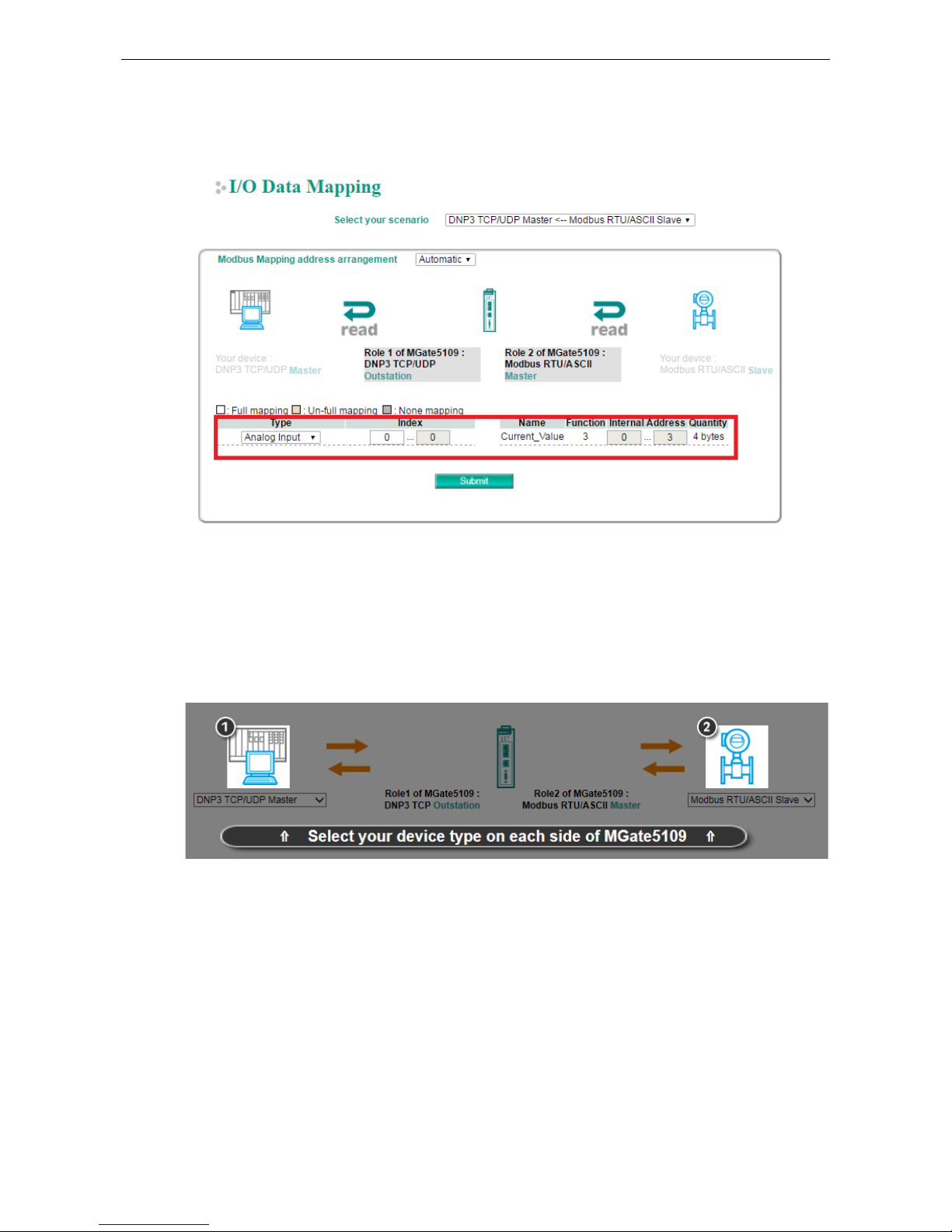
Example 2—MGate 5109 as DNP3 TCP Outstation (Role 1) and Modbus RTU Master (Role 2)
For the DNP3 master to control the Modbus coil command, we have created a command called Door_control.
The DNP3 type of the
Door_control command is set as Binary Output. BO [0] should be mapped to the
Door_control command as shown in the I/O Data Mapping table below. When the DNP3 TCP master sends
a write command to BO [0], MGate will trigger a
Door_control request to the Modbus slave.
Page 48
MGate 5109 Web Console Configuration and Troubleshooting
4-27
Likewise, if DNP3 TCP master wants to read the Modbus register command named Current_Value, the DNP3
type must first be set to Analog Input. The I/O Data Mapping table shows that AI [0] is mapped to the
Current_Value command. The DNP3 TCP master can read AI [0] of the outstation whose value will be
periodically updated because of the cyclic polling to the Modbus slave on the other side of the MGate.
Protocol Settings (Transparent Mode)
Modbus Transparent
Only the following combination can select transparent mode.
Page 49

MGate 5109 Web Console Configuration and Troubleshooting
4-28
Connected serial device's mode Device 1 Device 2
Master mode MB RTU/ASCII Master MB TCP Server
Slave mode MB TCP Client MB RTU/ASCII Slave
Protocol Settings—Modbus Transparent—Mode
Parameter Value Default Description
Transmission mode RTU
ASCII
RTU Modbus transmission mode
Response timeout 10-120000 ms 1000 According to the Modbus standard, the time it takes for a
slave device to respond to a request is defined by the
device manufacturer. Based on this response time, a
master can be configured to wait a certain amount of time
for a slave’s response. If no response is received within the
specified time, the master will disregard the request and
continue operation. This allows the Modbus system to
continue operation even if a slave device is disconnected or
faulty. On the MGate 5109, the Response timeout field is
used to configure how long the gateway will wait for a
response from a Modbus ASCII or RTU slave. R
efer to your
device manufacturer’s documentation to manually set the
response time.
The MGate 5109 can also auto-detect the response
timeout. Instead of manually figuring out the appropriate
setting, you can click Auto Detection to have the MGate
figure out the setting for you. Once a value has been
Slave mode Master mode
Modbus Serial
Slave
Modbus Serial
Master
Modbus TCP
Client
Modbus TCP
Server
Page 50

MGate 5109 Web Console Configuration and Troubleshooting
4-29
Parameter Value Default Description
recommended, you can fine-tune it to get the best
performance. You can specify the Modbus function and
starting address in the Auto Detection screen for different
devices. This function is only available when the MGate
5109 connects to Modbus RTU/ASCII slaves.
Inter-character
timeout
(only for Modbus RTU)
10-500 ms 0 Use this function to determine the timeout interval
between characters for Modbus devices that cannot receive
Rx signals within an expected time interval. If the response
is timed out, all the received data will be discarded. The
MGate 5109 will automatically determine the timeout
interval if the timeout value is set to 0.
Inter-frame delay
(only for Modbus RTU)
10-500 ms 0 The users can determine the time delay to transmit the
data frame received from the slave device to the upstream.
The MGate 5109 will automatically determine the time
interval if it is set to 0.
Protocol Settings—Modbus Transparent—Slave ID Map
In slave mode, the default slave ID mapping will define all Modbus IDs to serial port since the MGate 5109 only
has one serial port. In master mode, you have to add all the Modbus IDs manually.
You can add or modify the slave ID mapping via the Add or Edit button.
Parameter Value Default Description
Remote IP address 0.0.0.0 to 255. 255. 255.255 For Modbus TCP: the IP address of a
remote
slave device.
TCP Port 1-65535 For Modbus TCP: the TCP port number of a
remote slave device.
Slave ID Start 1-254 0 This specifies the range of IDs that will be
routed to the selected set of slave devices.
Slave ID End 1-254 0
Slave ID Offset -253 to 253 0 This specifies the difference between the
virtual slave ID and the actual slave ID. If a
slave’s virtual ID is 16 and the actual ID is
Page 51

MGate 5109 Web Console Configuration and Troubleshooting
4-30
Parameter Value Default Description
5, you would set the offset to -11. This
offset is applied to the entire range of
virtual slave IDs.
How Slave IDs are Mapped on the MGate 5109
With the slave ID table, smart routing is achieved for units with multiple serial ports. Since each virtual slave
ID is routed to a specific Modbus network, requests are not broadcast over all serial ports. This keeps
communication efficient and prevents devices on one port from slowing down the entire system.
When a Modbus master requests information from a Modbus slave device, the request is addressed to the
desired slave’s ID, which must be unique on the network. When Modbus networks are integrated by a Modbus
gateway, complications can arise if the same slave ID is being used on different networks. If this is not properly
addressed, a request sent to that slave ID would receive more than one response, causing communication
problems.
With the MGate 5109, this situation is addressed by using a slave ID map. While configuring the MGate, users
set up a range of “virtual” slave IDs that are mapped to slave devices on a specific Modbus network. To send
a request to a slave device that is on a different Modbus network, a Modbus master would address the request
to the appropriate (virtual) slave ID. The MGate then routes that request as specified by the slave ID map.
For example, if a TCP master needs information from an ASCII slave, it addresses the request to the
corresponding virtual slave ID as defined on the MGate’s slave ID map. The MGate identifies the request as
within its virtual slave ID range and forwards the request to the Modbus ASCII by the device’s actual slave ID.
Virtual slave IDs must not conflict with each other or with other TCP slave IDs.
When a serial port is set to RTU slave or ASCII slave mode, a virtual ID range will already be created for you.
Simply select the entry in the table and modify the range and offset as needed. For TCP slaves, you can add an
entry that assigns a range of virtual IDs to a specific IP address, using the Remote TCP Slave IP setting.
ATTENTION
The MGate 5109 will disregard any request that is not addressed to a virtual slave ID on its slave ID map. If a
device has not been assigned a virtual slave ID, it will not be accessible by masters on the other side of the
Modbus gateway.
Page 52

MGate 5109 Web Console Configuration and Troubleshooting
4-31
Protocol Settings—Modbus Transparent—Priority Control
The Priority Control tab is where emergency requests are enabled and configured.
Priority control is designed for requests that are sent to Modbus RTU/ASCII slaves. Since Modbus RTU/ASCII
slaves cannot handle multiple requests, the Modbus gateway must send each request individually and wait for
the response before sending the next request. As requests stack up, the response time can suffer. This can
cause problems for certain critical requests that require an immediate response.
With priority control, you can specify that certain requests are sent to the front of the queue for more
immediate response times. Priority requests can be specified by master (IP address or serial port), TCP port, or
command type (slave ID, function code, or data). When the Modbus gateway identifies a priority request, the
request will immediately be placed at the front of the queue.
To define a priority request, enable the appropriate priority scheme (i.e., Specified Masters, Specified TCP
Port, or Specified Requests). Then, specify the parameter(s) that will indicate a priority request. Finally,
click Add/Modify to apply this definition. (This last step is not necessary for Specified TCP Port.)
Protocol Settings—Modbus Transparent—Advanced Settings
The Advanced Settings tab is where certain adjustments can be made to fine-tune the communication between
different Modbus networks. You can configure Initial Delay, Modbus TCP Exception, Modbus TCP listen port,
Modbus TCP Response Time-out, and Self-Slave ID for digital I/O control.
Page 53

MGate 5109 Web Console Configuration and Troubleshooting
4-32
Parameter Value Default Description
Initial delay 0 – 3000ms 0
Some Modbus slaves may take more time to boot up than other
devices. For certain environments, this may cause the entire
system to suffer from repeated exceptions during the initial
boot-up. After booting up, you can force the MGate to wait
before sending the first request with the Initial Delay setting.
Modbus TCP
exception
Disable
Enable
Disable The MGate 5109 is a protocol gateway that transparently passes
requests and responses between the Ethernet and serial
interfaces. In some situations, it may be necessary for the
gateway to return an exception in response to a request from a
Modbus TCP master. This is enabled or disabled with the
Modbus TCP Exception setting. When enabled, the unit can
return two types of exception:
Modbus TCP
listen port
1-65535 502 Allow you to change Modbus TCP listen port from the default
value (502).
Modbus TCP
response
timeout
10-120000 1000 According to the Modbus standard, the time that it takes for a
slave device to respond to a request is defined by the device
manufacturer. Based on this response time, a master can be
configured to wait a certain amount of time for a slave’s
response. If no response is received within the specified time,
the master will disregard the request and continue operation.
This allows the Modbus system to continue operation even if a
slave device is disconnected or faulty.
On the MGate 5109, the Modbus TCP response timeout
field
is used to configure how long the gateway will wait for a
response from a Modbus ASCII or RTU slave. Refer to your
device manufacturer’s documentation to manually set the
response timeout.
Modbus TCP exception
Exception Conditions
Timeout There is no response from the slave. Maybe the device is off-line or the serial
cable is broken.
Request dropped There are two situations that will result in this exception:
The request queue is full (32 request queue for each master)
The destination ID is not included in the slave ID map.
Not all Modbus TCP masters require this exception, so it is up to you to determine if this setting should be
enabled.
DNP3 Transparent
The MGate 5109 series supports DNP3 transparent mode. Only the following combination can select
transparent mode:
Page 54

MGate 5109 Web Console Configuration and Troubleshooting
4-33
Connected serial device's mode Device 1 Device 2
Master mode DNP3 serial Master DNP3 TCP/UDP Outstation
Outstation mode DNP3 TCP/UDP Master DNP3 Serial Outstation
Add all DNP3 devices into the table, including master and all outstations.
Parameter Value Default Description
IP address 0.0.0.0 to
255.255.255.255
The IP address of remote DNP3 device.
Port 1-65535 20000 DNP3 default using port 20000.
DNP3 address Start
0-65519
0
This specifies the range of IDs that will be routed to
the selected set of slave devices.
DNP3 address End 0-65519 0
DNP3 address Offset 0-65519 0 This specifies the difference between the virtual
slave
ID and the actual slave ID. If a slave’s virtual
ID is 16 and the actual ID is 5, you would set the
offset to -11. This offset is applied to the entire
range of virtual slave IDs.
Page 55

MGate 5109 Web Console Configuration and Troubleshooting
4-34
For DNP3 packet frames from Ethernet side, you need to assign a serial port along with related ranges of DNP3
addresses to receive these DNP3 data packets. Similarly, for DNP3 packet frames coming from the serial side,
you need to assign the DNP3 device’s address and IP address. The default IP address is 192.168.1.1; modify
the IP address based on your DNP3 equipment settings. If there are multiple outstation devices on the Ethernet
side, you will need to add these devices’ IP addresses and DNP3 addresses to the routing table. The gateway
will drop a DNP3 packet frame if the destination DNP3 device address or IP address is not defined in the
gateway.
Protocol Settings—DNP3 Transparent—Advanced Settings
Allows you to change the default value (20000) of the DNP3 TCP listen port.
Parameter Value Default Description
Listen port 1-65535 20000 The default DNP3 TCP listen port is 20000; you can change
it to any number between 1 and 65535.
System Management
System Management—Accessible IP List
These settings are used to restrict access to the module by the IP address. Only IP addresses on the list will be
allowed access to the device. You may add a specific address or range of addresses by using a combination of
an IP address and a netmask as follows:
To allow access to a specific IP address: Enter the IP address in the corresponding field; enter
255.255.255.255 for the netmask.
To allow access to hosts on a specific subnet: For both the IP address and netmask, use 0 for the last digit
(e.g., “192.168.1.0” and “255.255.255.0”).
To allow access to all IP addresses: Make sure that Enable the accessible IP list is not checked.
Page 56

MGate 5109 Web Console Configuration and Troubleshooting
4-35
Additional configuration examples are shown in the following table:
Desired IP Range IP Address Field Netmask Field
Any host Disable Enable
192.168.1.120 192.168.1.120 255.255.255.255
192.168.1.1 to 192.168.1.254 192.168.1.0 255.255.255.0
192.168.1.1 to 192.168.255.254 192.168.0.0 255.255.0.0
192.168.1.1 to 192.168.1.126 192.168.1.0 255.255.255.128
192.168.1.129 to 192.168.1.254 192.168.1.128 255.255.255.128
System Management—DoS Defense
Users can select from several options to enable DoS Defense in order to fend off cybersecurity attacks. A
denial-of-service (DoS) attack is an attempt to make a machine or a network resource unavailable. Users can
select from the following options to counter DoS attacks.
System Management—System Log Settings
Page 57

MGate 5109 Web Console Configuration and Troubleshooting
4-36
The system log settings enable the MGate firmware to record important events for future verification. The
recorded information can only be displayed on the web console.
The available information that can be recorded includes the following events:
Event Group Description
System System Cold Start, System Warm Start
Network
DHCP/BOOTP Get IP/Renew, NTP Connect Fail, IP Conflict, Network Link Down
Configuration
Login Fail, IP Changed, Password Changed, Firmware Upgrade, SSL Certificate
Import, Configuration Import/Export
DNP3 TCP/UDP DNP3 TCP/UDP Communication logs
Modbus TCP Modbus TCP Communication logs
Local Log Settings Description
Enable log capacity warning
(%)
When the log amount exceeds the warning percentage, it will trigger an
event
to SNMP Trap or Email.
Warning by SNMP Trap
Email
Event log oversize action Overwrites the oldest event log
Stops recording event log
Syslog Settings Description
Syslog server IP IP address of a server which will record the log data.
Syslog server port 514
System Management—Auto Warning Settings
Auto Warning is triggered by different events. When a checked trigger condition occurs, the MGate can send
email alerts, SNMP Trap messages, or open/close the circuit of the relay output and trigger the Fault LED to
start blinking. To enable an email alert, configure the email address on the Email Alert page. Likewise, to
enable SNMP trap alerts, configure SNMP trap server on the SNMP Trap page.
Page 58

MGate 5109 Web Console Configuration and Troubleshooting
4-37
System Management—Email Alert
Parameters Description
Mail server (SMTP) The mail server’s domain name or IP address.
User name This field is for your mail server’s user name, if required.
Password This field is for your mail server’s password, if required.
From email address This is the email address from which automatic email warnings will be sent.
To email address 1 to 4 Email addresses to which automatic email warnings will be sent.
System Management—SNMP Trap
Parameters Description
SNMP trap server IP Use this field to indicate the IP address to use for receiving SNMP traps.
Trap version Use this field to select the SNMP trap version.
Trap community Use this field to designate the SNMP trap community.
Page 59

MGate 5109 Web Console Configuration and Troubleshooting
4-38
System Management—SNMP Agent
Parameters Description
SNMP To enable the SNMP Agent function, select the Enable option, and enter a
community name (e.g., public).
Contact name The optional SNMP contact information usually includes an emergency contact
name and telephone number.
Read community string This is a text password mechanism that is used to weakly authenticate queries to
agents of managed network devices.
Write community string This is a text password mechanism that is used to weakly authenticate changes to
agents of managed network devices.
SNMP agent version The MGate 5109 supports SNMP V1, V2c, and V3.
Read-only and Read/write access control
The following fields allow you to define user names, passwords, and authentication parameters for two levels
of access: read-only and read/write. The name of the field will indicate which level of access it refers to. For
example, Read-only authentication mode allows you to configure the authentication mode for read-only
access, whereas Read/write authentication mode allows you to configure the authentication mode for
read/write access. For each level of access, you may configure the following:
Parameters Description
User name Use this optional field to identify the user name for the specified level of access.
Authentication mode Use this field to select MD5 or SHA as the method of password encryption for the
specified level of access, or to disable authentication.
Privacy mode Use this field to enable or disable DES_CBC data encryption for the specified lev
el of
access.
Password Use this field to set the password for the specified level of access.
Privacy Use this field to define the encryption key for the specified level of access.
Page 60

MGate 5109 Web Console Configuration and Troubleshooting
4-39
System Management—LLDP Settings
The Link Layer Discovery Protocol (LLDP) standardizes the method that devices on a network use to periodically
send information on their configuration and status. This self-identification method keeps all LLDP devices on a
network informed of each other's status and configuration. You can use SNMP protocol to then send the LLDP
information on the network devices to Moxa's MXview to create auto network topology and for network
visualization.
The MGate web interface lets you enable or disable LLDP, and set the LLDP transmit interval. In addition, you
can go to System Monitoring–System Status–LLDP Table to view the MGate’s neighbor-list, which is
created based on the information reported by neighboring devices on the network.
Parameters Values Description
Message transmit interval 5–16383 secs (Default:30
secs)
MGate will send information on the configuration
and status of devices in a network at regular
intervals based on the value configured here.
System Management—Certificate
Use this function to load the Ethernet SSL certificate. Select or browse for the certificate file in the Select SSL
certificate/key file field. This function is only available in the web console.
Page 61

MGate 5109 Web Console Configuration and Troubleshooting
4-40
System Management—Misc. Settings
This page includes console settings, password and relay output.
System Management—Misc. Settings—Console Settings
Configuration Value Description
HTTP/HTTPS
Enable/Disable
This setting is to enable/disable the web console. For security
issues, users can only enable the HTTPS or just disable all
settings.
Telnet/SSH Enable/Disable
Serial console Enable/Disable
Reset button
protect
Disable after 60 sec,
Always enable
MGate provides the reset button to clear password or load
factory default settings. But for security issues, users can disable
this function. In disabled mode, MGate will still enable this
function within 60 seconds after boot-up, just in case users
really need to reset this function.
MOXA command Enable/Disable
Session Settings Value Description
Maximum Login User for
HTTP+HTTPS
1-10
Auto Logout Setting 0-1440 min. Sets the auto logout time period.
Page 62

MGate 5109 Web Console Configuration and Troubleshooting
4-41
System Management—Misc. Settings—Notification Message
Users can input a message for Login or for Login authentication failure message.
System Management—Misc. Settings—Account Management
Parameters Value Description
Account admin, user Users can modify the password for different accounts. MGate provides
two different level accounts: admin and user. Admin account can
access and modify all the settings through the web console. User
account can only view the setting and can’t change anything.
Page 63

MGate 5109 Web Console Configuration and Troubleshooting
4-42
System Management—Misc. Settings—Login Password Policy
Account Password Policy Value Description
Minimum length 4-16
Enable password complexity
strength check
Select how the MGate checks the password’s strength
Password lifetime
90-180 days
Set the password’s lifetime period.
Account Login Failure
Lockout
Value Description
Retry failure threshold 1-10 time
Lockout time 1-60 min
System Management—Maintenance
System Management—Maintenance—Ping
This network testing function is available only in the web console. The MGate gateway will send an ICMP packet
through the network to a specified host, and the result can be viewed in the web console immediately.
System Management—Maintenance—Firmware Upgrade
Firmware updates for the MGate 5109 are located at www.moxa.com. After you have downloaded the new
firmware onto your PC, you can use the web console to write it onto your MGate 5109. Select the desired unit
from the list in the web console and click Submit to begin the process.
Page 64

MGate 5109 Web Console Configuration and Troubleshooting
4-43
ATTENTION
DO NOT turn off the MGate power before the firmware upgrade process is completed. The MGate will be erasing
the old firmware to make room for the new firmware to flash memory. If you power off the MGate and
terminate the progress, the flash memory will contain corrupted firmware and the MGate will fail to boot. If this
happens, call Moxa RMA services.
System Management—Maintenance—Configuration Import/Export
There are three main reasons for using the Import and Export functions:
• Applying the same configuration to multiple units. The Import/Export configuration function is a
convenient way to apply the same settings to units located in different sites. You can export the
configuration as a file and then import the configuration file onto other units at any time.
• Backing up configurations for system recovery. The export function allows you to export configuration
files that can be imported onto other gateways to restore malfunctioning systems within minutes.
• Troubleshooting. Exported configuration files can help administrators to identify system problems that
provide useful information for Moxa’s Technical Service Team when maintenance visits are requested.
System Management—Maintenance—Load Factory Default
To clear all the settings on the unit, use the Load Factory Default to reset the unit to its initial factory default
values.
ATTENTION
Load Default
will completely reset the configuration of the unit, and all of the parameters you
have saved will
be discarded. Do not use this function unless you are sure you want to completely reset your unit.
Page 65

MGate 5109 Web Console Configuration and Troubleshooting
4-44
System Monitoring (Troubleshooting)
MGate 5109 provides easy-to-use and useful troubleshooting tools. If a communication issue occurs, we
suggest that you first check the Protocol Status > Diagnosis page for the status of the protocol. To analyze
the Modbus/DNP serial traffic in detail, view the network logs available at Protocol Status > Traffic.
System Monitoring—System Status
System Monitoring—System Status—Network Connections
Go to Network Connections under System Status to view network connection information.
System Monitoring—System Status—System Log
Go to Network Connections under System Status to view network connection information.
System Monitoring—System Status—Relay State
The MGate gateway includes a built-in relay circuit that is triggered in the event of a power failure or if the
Ethernet link is down. You can view the relay status on this page.
Page 66

MGate 5109 Web Console Configuration and Troubleshooting
4-45
System Monitoring—System Status—LLDP Table
You can see LLDP related information, including Port, Neighbor ID, Neighbor Port, Neighbor Port Description,
and Neighbor System.
System Monitoring—Protocol Status
System Monitoring—Protocol Status—I/O Data View
This page displays the internal memory information for input and output data transfers. View updated values
for communication verification here. This function is only available in the web console.
System Monitoring—Protocol Status—Diagnose
The MGate provides status information for DNP3, Modbus RUB/ASCII, and Modbus TCP troubleshooting. Verify
data or packet counters to make sure the communications are running smoothly.
Modbus RTU/ASCII Diagnose (Master)
Page 67

MGate 5109 Web Console Configuration and Troubleshooting
4-46
Modbus RTU/ASCII Diagnose (Slave)
Modbus TCP Diagnose (Client/Master)
Modbus TCP Diagnose (Slave/Server)
Page 68
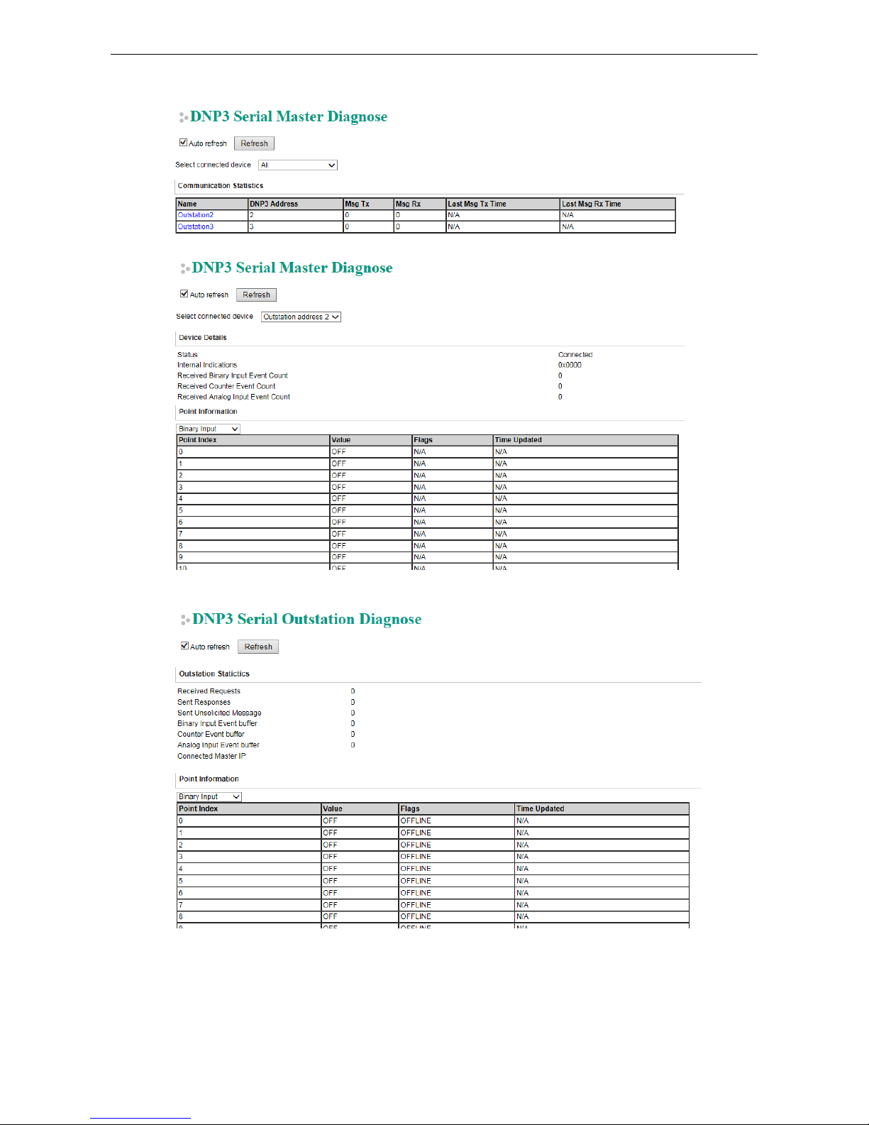
MGate 5109 Web Console Configuration and Troubleshooting
4-47
DNP3 Serial Master Diagnose
DNP3 Serial Outstation Diagnose
Page 69
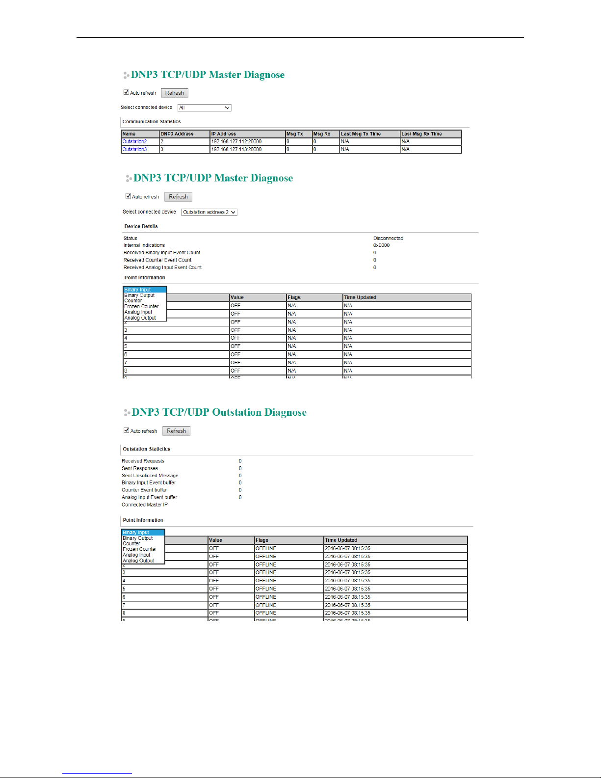
MGate 5109 Web Console Configuration and Troubleshooting
4-48
DNP3 TCP/UDP Master Diagnose
DNP3 TCP/UDP Outstation Diagnose
Page 70

MGate 5109 Web Console Configuration and Troubleshooting
4-49
System Monitoring—Protocol Status—Traffic
Modbus RTU/ASCII Traffic
For troubleshooting or management purposes, you can monitor the Modbus RTU/ASCII data passing through
the MGate 5109 on the network. Rather than simply echoing the data, MGate Manager presents the data in an
intelligent, easy-to-understand format with clearly designated fields, including source, type, destination,
contents, and more. Events can be filtered in different ways, and the complete log can be saved to a file for later
analysis.
DNP3 Serial Traffic
Page 71

MGate 5109 Web Console Configuration and Troubleshooting
4-50
Status Monitoring
Status Monitoring helps users monitor slave device communication status by PLC/SCADA master. (See
schematic diagram below.) The status monitoring only works when the MGate acts as the “Master”. This
function always works in the background while the MGate is operating. If there are no issues, MGate will not list
any monitored information. But when an error occurs, MGate will list the status into the specified memory,
which can be retrieved by PLC/SCADA via Ethernet/IP or Modbus protocol. Once the issue is solved, MGate will
eliminate the error status.
Format:
The maximum number of entries for Status Monitoring lists is 30. Each entry frame has eight bytes, which
contains the information of device ID, information group, and protocol information content. The format is:
4 bytes 1 byte 3 bytes
Device ID Information Group Type Protocol Information
Device ID:
The first four bytes of the status monitoring data represent the device ID, which could be an IPv4 address or a
Modbus slave ID (for example: Modbus slave ID).
Information Group Type:
The 5th byte is the information group, which is defined below:
0x00:
Reserved, currently not use.
0x01:
Connection info group, which represents for the connection drop or other error related to connection
step. 0x02:
Protocol related status information, which will be defined by each protocol.
0x03:
Moxa defined status
.
0x04:
Vendor specified.
Protocol Information:
The Protocol Information will be influenced by the Information Group.
If the value in the Information Group is 0x01, the three protocol information bytes will take the value 0x00,
0x00, 0xFF. This means a slave device was disconnected or unable to connect successfully.
Information Group Protocol Information
1 byte 1 byte 1 byte 1 byte
0x01 0x00 0x00 0xFF
If the Information Group is 0x02, different protocols of the format will be different.
Page 72

MGate 5109 Web Console Configuration and Troubleshooting
4-51
Modbus Master Error:
Information Group Protocol Information
1 byte 1 byte 1 byte 1 byte
0x02 Reserved
(should be all 0)
Modbus
Function code
Modbus
Exception code
For details regarding the Modbus function code and exception code, refer to Modbus protocol specification.
A slave device was disconnected or unable to connect success:
1
st
& 2nd bytes: Should be all 0.
3
rd
byte: Should be 0xFF.
After the slave device was connected:
1
st
byte: Reserved, should be all 0.
2
nd
byte: The function code of the Modbus command when an error occurs.
3
rd
byte: The Modbus exception code that the slave device responds to (refer to the specification of the
corresponding slave device). When the device disconnects or the connection times out, the exception code will
be 0xFF.
DNP3 Master Error:
Information Group Protocol Information
1 byte 1 byte 1 byte 1 byte
0x02 Reserved
(should be all 0)
DNP3
IIN2.X (MSB)
DNP3
IIN1.X (LSB)
The Slave device was disconnected or unable to connect success:
1st & 2nd bytes: should be all 0.
3rd byte: should be 0xFF.
After the slave device was connected:
1st byte: reserved, should be all 0.
2nd byte: the IIN2.X (MSB) from outstation response fragment.
3rd byte: the IIN1.X (LSB) from outstation response fragment.
When the IIN occurs below, field device status monitoring data will be generated:
IIN1.6 device trouble
IIN2.0 function code not support
IIN2.1 object unknown
IIN2.2 parameter error
IIN2.3 event buffer overflow
IIN2.5 configuration corrupt
Access method:
Modbus:
If user’s device is Modbus master (client), and MGate acts as a Modbus slave (server), user can get the status
monitoring information through function code 0x03, with protocol register address 10000 (in PLC view, the
address is 10001); Quantity 1 to 120 (total 240 bytes).
Page 73
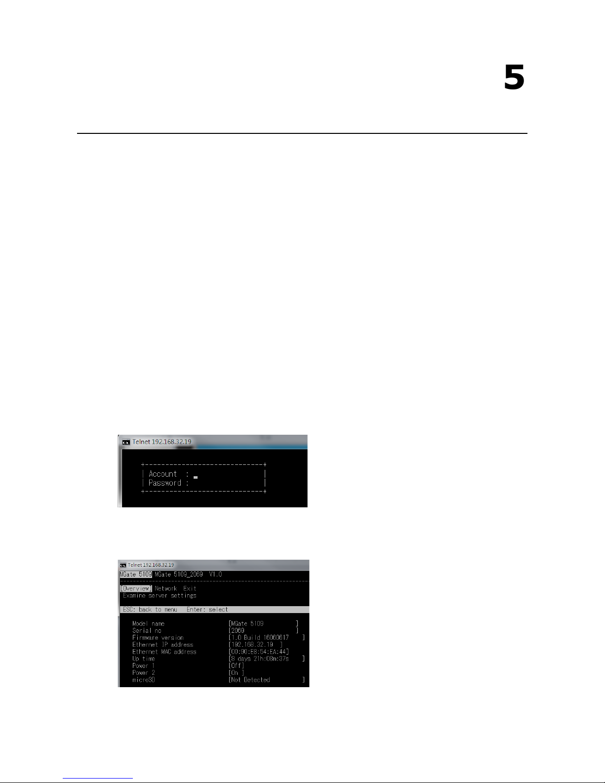
5
5. Configuration (Text Mode Console)
The MGate 5109 supports a text-mode console with serial interface, telnet, and SSH protocol. The user
interface is the same in all text mode consoles. Note that the text mode console does not support all
configuration items. Some parameters must be configured through the web console.
You must use a DB9-to-RJ45 cable to connect the serial console port on the MGate gateway’s front panel to the
serial port on the host. The serial console parameters are 115.2 kbps; parity: none; 8 data bits; and one stop
bit.
For telnet and SSH, use HyperTerminal or PuTTY to connect to the MGate. Note that the telnet protocol will
transfer the account and password information over the Internet using plain text, so telnet is essentially
obsolete and should be replaced by the SSH protocol.
To connect to the MGate telnet/SSH console, load the telnet/SSH program and connect to the MGate IP
address.
For the serial interface, use a null modem (crossover) cable to connect the serial port on the host to the serial
console port on the MGate’s front of panel. The serial console parameters are 115.2kbps, none for parity, 8 data
bits, and one stop bit. You can use a terminal program such as PComm Terminal Emulator or PuTTY to connect
to the MGate serial console.
On the first page, input the account and password. The account supports two types of users: admin and user.
An “admin” account can modify all of the settings, but a “user” account can only review the settings. A “user”
account cannot modify the configuration. The default password for admin is moxa.
The text mode console will display the menu driven interface. Users can use arrow key to move the menu bar.
To select the option, press the “Enter” key to go next level menu. To go previous level menu, press “Esc” key
to quit. If necessary, MGate will need to restart to activate the setting.
Page 74

6
6. Network Management Tool (MXstudio)
This chapter provides an overview of Moxa’s MXstudio industrial network management suite.
The following topics are covered in this chapter:
Overview
Page 75

MGate 5109 Network Management Tool (MXstudio)
6-2
Overview
Moxa’s MXstudio industrial network management suite includes tools that you might need throughout your
industrial network life cycle such as MXconfig industrial network configuration tool, MXview industrial
management software, and N-Snap industrial network snapshot tool. The MXstudio suite in MGate 5109
includes MXconfig and MXview, which are used for mass configuration of network devices and monitoring
network topology, respectively. The following functions are supported:
Tool Function Support
MXconfig 1. System name and login password modification
2. Network settings
3. Configuration import/export
4. Firmware upgrade
MXview 1. Configuration import/export
2. LLDP for topology analysis
3. Security View**
** Security features based on IEC-62443 standard.
 Loading...