

Page 1
– 1 – – 2 – – 3 –
P/N: 1802051050011
MGate 5105-MB-EIP
Quick Installation Guide
Second Edition, Jun e 2014
Overview
The MGate 5105-MB-EIP is an industrial Ethernet gateway for
Modbus RTU/ASCII/TCP and EtherNet/IP network communication.
Package Checklist
Before installin g the MGate 5105-MB-EIP, verify that the package
contains the fo llowing items:
• 1 MGate 5105-MB-EIP gateway
• RJ45 to DB9 cable (for console use)
• Documentation and softwar e CD
• Quick installation guide
• Warranty card
Optional Accessories:
• DR-45-24: 45W/2A DIN ra il 24 VDC power supply with
universal 85 to 2 64 VAC input
• DR-75-24: 75W/3.2A D IN rail 24 VDC pow er supply with
universal 85 to 2 64 VAC input
• DR-120-24: 120W/5A DIN rail 24 VDC power supply with 88 to
132 VAC/176 to 264 VAC input by switch
• WK-36-02: Wall moun ting kit
• Mini DB9F-to-TB Adaptor: DB9 female to terminal block
adapter
Please notify your sales representative if any of the above items
are missing or damaged.
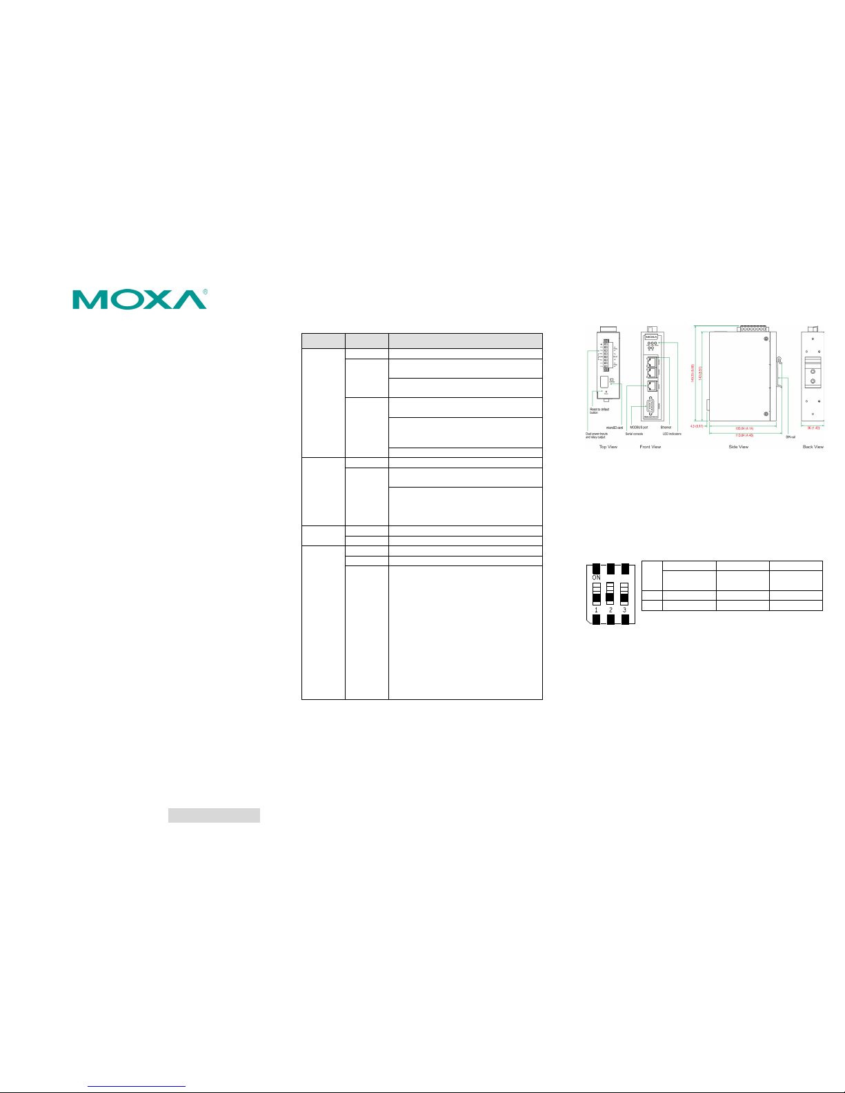
Hardware Introduction
LED Indicators
LED
Color
Description
Ready
Off
Power is off or fault condition exists
Green
Steady: Power is on and the MGate is
functioning normally
Blinking: The M Gate has been loc ated by
the MGate Manager’s Location function
Red
Steady: Power is on and the MGate is
booting up
Blinking slowly: Indicates an IP conflict, or
DHCP or BOOTP server is not responding
properly
Flashing quickly : microSD card failed
EIP
(Scanner)
Off
No I/O data is exchanged
Green
Steady: I/O data is exchanged with all
devices
Blinking: I/O da ta is exchanged with at
least one device
(Not all configured device s can
communicate with gateway)
EIP
(Adapter)
Off
No I/O data is exchanged
Green
I/O data is exchanged with all devices
MB
Off
No communication with Modbus device
Green
Modbus communication progress
Red
Communication error
When MGate 5105 acts as Master:
1. Slave device returned an error
(exception)
2. Received frame error
(parity error,
checksum error)
3. Timeout (slave device no
response)
When MGate 5105 acts as Slave:
1. Rece ived invalid func tion code
2. Master accessed inv alid register
address or coil addresses
3. Received frame error
(parity error,
checksum error)
Dimensions
Unit: mm (inch)
Reset Button
Restore the MGate to factory default settings by using a pointed
object (such as a straightened paper clip) to hold the reset button
down until the Ready LED stops blinking (approx. 5 seconds).
Pull-high, Pull-low, and Terminator for RS-485
Remove the MGate 5105-MB-EIP’s top cover and you will find DIP
switches to adjust each serial port’s pull-high resistor, pull-low
resistor, and terminator.
SW
1 2 3
Pull-high
resistor
Pull-low
resistor
Terminator
ON
1 kΩ
1 kΩ
120 Ω
OFF
150 kΩ*
150 kΩ*
–*
*Default
Page 2
– 4 – – 5 – – 6 –
www.moxa.com/support
The Americas:
+1-714-528-6777 (toll-free: 1-888-669-2872)
Europe:
+49-89-3 70 03 99-0
Asia-Pacific:
+886-2-8919-1230
China:
+86-21-5258-9955 (toll-free: 800-820-5036)
2014 Moxa Inc. All rights reserved.
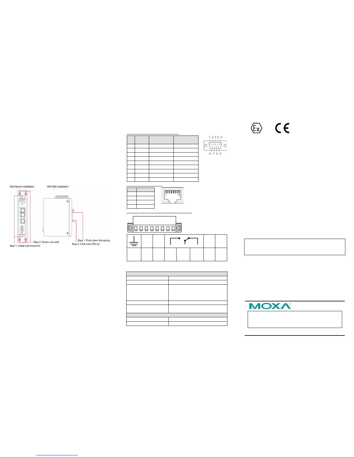
Hardware Installation Procedure
1. Connect the power adap ter. Connect the 12-48 VDC power line
or DIN rail power supply to the MGate 5105-MB-EIP de vice’s
terminal block.
2. Use a Modbus serial cable to connect the MGa te to a Modbus
slave device.
3. Use an Ethernet cable to connect the MGate to the EtherNet/IP
controller.
4. The MGate 5105-MB-E IP is designed to be attached to a
DIN rail or mounted on a wall. For DIN rail mounting, push
down the spring and properly attach it to the DIN rail until it
“snaps” into place. For wall mounting, ins tall the wall mount kit
(optional) first, and then screw the device onto the wall. The
following figur e illustrates the two mounting options:
Software Installation Information
To install MGate Manager, insert the MGate Documentation and
Software CD into your PC’s CD-ROM drive, and then run the
following setup program to begin the installation process from the
“Software” directory:
MGM_Setup_[Ver sion]_Build_[D ateTime].exe
The filename of the latest version may have the following format:
MGM_Setup_Ver x.x.x_Build_xxxxxxxx.exe.
For detailed information about MGate Manager, refer to the MGate
5105-MB-EIP User's Manual, which can be found in the “Document”
directory .
Pin Assignments
Modbus Serial Port (Male DB9)
Pin
RS-232
RS-422/
RS-485 (4W)
RS-485 (2W)
1
DCD
TxD-(A)
– 2 RXD
TxD+(B)
–
3
TXD
RxD+(B)
Data+(B)
4
DTR
RxD-(A)
Data-(A)
5
GND
GND
GND
6
DSR – –
7
RTS – –
8
CTS – –
9 – –
–
Ethernet Port (RJ45)
Pin
Signal
1
Tx+
2
Tx-
3
Rx+
6
Rx-
Power Input and Relay Output Pinouts
V2+ V2-
V1+ V1-
Shielded
Ground
DC
Power
Input 2
DC
Power
Input 2
N.O.
Common
N.C.
DC
Power
Input 1
DC
Power
Input 1
Specifications
Power Requirements
Power Input
12 to 48 VDC
Power Consumption
455 mA @ 12 VDC, 125 mA @ 48 VDC
Operating Temperature Standard models: 0 to 60°C (32 to
140°F)
Wide temp. models: -40 to 75°C (-
40
to 167°F) for –T model
Ambient Rela tive Humidity
5 to 95% RH
Dimensions
36 x 105 x 140 mm
(1.42 x 4.13 x 5.51 in)
Reliability
Alert Tools
Built-in buzzer and RTC
MTBF
513,139 hrs
1. DEMKO Certifica tion number: 13 ATEX 1307610X
IEC Certificat ion Number: IECE x UL 13.0051X;
2. Ambient Temperature Range (-40°C ≤ Tamb ≤ 75°C)
3. Certification String: Ex nA nC IIC T3 Gc
4. Standards Covered: EN 60079-0:2012/IEC 60079-0 6th Ed.
AND EN 60079-15:2010/IEC 60079-15 4th Ed.
5. The conditions of safe usage:
a. The Ethernet Communications Devices are intended for
mounting in a tool-accessible IP54 enclosure and used in
an area of not more than pollution degree 2 as defined by
IEC 60664-1.
b. Conductors suitable for use in an ambient temperature
greater than 86°C must be used for the power supply
terminal.
c. A 4mm
2
conductor must be used when connection to the
external ground ing screw is util ized.
d. Provisions shall be made, either in the equipment or
external to the equipment, to prevent the peak rated
voltage being exceeded by the transient disturbances of
more than 140%.
Terminal Block (P lug mated with Socket): Rated 300 V, 10 A,
105°C, 12-28 AWG (0.0804 mm
2
- 3.31 mm2) wire size, torq ue
value 4.5 lb- in (0.509 N-m). The input terminal c able size 14 AWG
(2.1 mm
2
).
Moxa Inc.
Fl. 4, No. 135, Lane 235, Baoqiao Rd.
Xindian Dist., N ew Taipei City, 23145
Taiwan, R.O .C.
 Loading...