

Page 1

P/N: 1802051030010
*1802051030010*
Technical Support Contact Information
www.moxa.com/support
Moxa Americas:
Toll
Tel:
Fax:
Moxa China (Shanghai office):
Toll
Tel:
Fax:
Moxa Europe:
Tel:
Fax:
Moxa Asia-Pacific:
Tel:
Fax:
Moxa India:
Tel:
Fax:
2017 Moxa Inc. All rights reserved.
MGate 5103
Quick Installation Guide
Edition 1.0, December 2017
-free: 1-888-669-2872
1-714-528-6777
1-714-528-6778
+49-89-3 70 03 99-0
+49-89-3 70 03 99-99
+91-80-4172-9088
+91-80-4132-1045
-free: 800-820-5036
+86-21-5258-9955
+86-21-5258-5505
+886-2-8919-1230
+886-2-8919-1231
Page 2

Overview
The MGate 5103 is an industrial Ethernet gateway for Modbus
RTU/ASCII/TCP, EtherNet/IP, and PROFINET network co mmunication s.
Package Checklist
Before installing the MGate 5103, verify that the package contains the
following items:
• 1 MGate 5103 gateway
• 1 serial cable: DBL-RJ45F9-150
• Documentation
• Quick insta llation guide (printed)
• Warranty card
Please notify your sales representative if any of the above items is
missing or damaged.
Optional Accessories (can be purchased separately)
• CBL-F9M9-150: DB9-female-to-DB9-male serial cable, 150 cm
• CBL-F9M9-20: DB9-female-to-DB9-male serial cable, 20 cm
• CBL-RJ45SF9-150: RJ45-to-DB9-fema le shielded serial cable, 150
cm
• ADP-RJ458P-DB9F: DB9-female-to-RJ45 connector
• ADP-RJ458P-DB9F-ABC01: DB9-female-to-RJ45 connector
• Mini DB9F-to-TB: DB9-female-to-terminal-block connector
- 2 -
Page 3
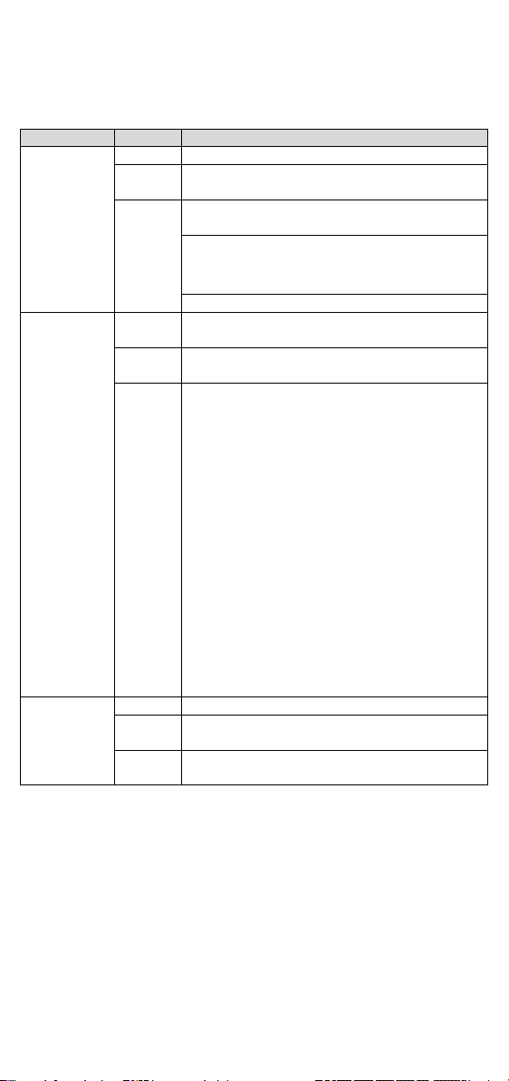
LED
Color
Description
Ready
Off
Power is off or a fault condition exists
Green
Steady: Power is on, and the MGate is
functioning normally
up
Blinking slowly: Indicates an IP conflict, or the
Flashing quickly: the microSD card failed
MB/EIP
Off
Modbus: No communication with Modbus dev ice
EtherNet/IP: No I/O data exchange
Green
(Blinking)
Modbus: Communication in progress
EtherNet/IP: I/O data is exchanging
(Blinking)
3. Timeout (slave device is not responding or
hecksum
configuration
Off
No connection with PROFINET I/O contro ller
Green
(Blinking)
controller is
in RUN mode
Red
(Blinking)
PROFINET I/O is connected, but the controller is
in STOP mode
Hardware Introduction
LED Indicators
Red Steady: Power is on, and the MGate is booting
DHCP or BOOTP server is not responding
properly
Red
PN
Communication error
When MGate 5103 acts as Modbus
Client/Master:
1. Slave device returned an error (exception)
2. Received a frame error (parity error,
checksum error)
TCP connection timed out)
When MGate 5103 acts as Modbus
Server/Slave:
1. Received invalid function code
2. Master accessed invalid register address or
coil addresses
3. Received frame error (parity error, c
error)
When MGate 5103 acts as EtherNet/IP adapter:
1. Refuses connection due to incorrect
PROFINET I/O is connected and the
- 3 -
Page 4

1 2 3
resistor
resistor
ON
1 kΩ
1 kΩ
120 Ω
OFF
150 kΩ*
150 kΩ*
–*
*Default
Dimensions
Unit: mm (inch)
Reset Button
Restore the MGate to factory default settings by using a pointed object
(such as a straightened paper clip) to hold the reset button down until the
Ready LED stops blinking (approximately five seconds).
Pull-up, Pull-down, and Terminator for RS-485
Beneath the MGate 5103’s top cover, you will find DIP switches to adjust
each serial port’s pull-up resistor, pull-down resistor, and terminator.
SW
Pull-up
Pull-down
Terminator
Hardware Installation Procedure
1. Connect the power adapter. Connect the 12-48 VDC power line or
DIN-rail power supply to the MGate 5103’s terminal block.
2. Use a serial cable to connect the MGate to the Modbus device.
3. Use an Ethernet cable to connect the MGate to the PROFINET IO
controller.
4. The MGate 5103 is designed to be attached to a DIN rail or mounted
on a wall. For DIN-rail mounting, push down the spring and properly
attach it to the DIN rail until it “snaps” into place. For wall mounting,
install the wall-mounting kit (optional) first and then screw the device
onto the wall.
The following figure illustrates the two mounting options:
- 4 -
Page 5

RS-422/
RS-485 (4W)
1
DCD
TxD-(A)
–
2
RXD
TxD+(B)
–
3
TXD
RxD+(B)
Data+(B)
4
DTR
RxD-(A)
Data-(A)
5*
GND
GND
GND
6
DSR – –
7
RTS – –
8
CTS – – 9 – – –
Pin
Signal
1
Tx+ 2 Tx- 3 Rx+ 6 Rx-
Software Installation Information
The MGate 5103 also supports login via a web browser.
Default IP address: 192.168.127.254
Default account: admin
Default password: moxa
Pin Assignments
Modbus Serial Port (Male DB9)
Pin RS-232
RS-485 (2W)
*Signal ground
Ethernet Port (RJ45)
Power Input and Relay Output Pinouts
- 5 -
Page 6

DC
Input 2
DC
Input 2
DC
Input 1
DC
Input 1
Power Requirements
Power Input
12 to 48 VDC
Power Consumption
455 mA @ 12 VDC, 125 mA @ 48 VDC
Operating Temperature
Standard models:
-40 to 75°C (-40 to 167°F)
Ambient Relative Humidit y
5 to 95% RH
Dimensions
36 x 105 x 140 mm (1.42 x 4.13 x 5.51 in)
Reliability
Alert Tools
Built-in buzzer and RTC
MTBF
859,422 hrs.
V2+ V2-
V1+ V1-
Shielded
Ground
Power
Power
N.O. Common N.C.
Power
Power
Specifications
0 to 60°C (32 to 140°F)
Wide temp. models:
1. DEMKO Certification number: 13 ATEX 1307610X
IEC Certification Number: IECEx UL 13.0051X;
2. Ambient Temperature Range:
0°C to 60°C (for models without suffix –T)
-40°C to 75°C (for models with suffix –T only)
3. Certification String: Ex nA nC IIC T3 Gc
4. Standards Covered: EN 60079-0:2013+A11:2013/IEC 60079-0 6th
Ed. AND EN 60079-15:2010/IEC 60079-15 4th Ed.
5. The conditions of safe use:
a. Ethernet Communications Devices are intended for mounting in a
tool-accessible IP54 enclosure and use in an area of not more
than pollution degree 2 as defined by IEC/EN 60664-1.
b. Conductors suitable for use in an ambient temperature greater
than 86°C must be used for the power supply terminal.
c. A 4mm
d. Provisions shall be made, either in the equipment or external to
Terminal block (plug matched with socket): rated at 300 V, 15 A, 105°C,
12-28 AWG (0.0804 mm
(0.509 N-m). The input terminal cable size: 14 AWG (2.1 mm
2
conductor must be used when a connection to the
external grounding screw is utilized.
the equipment, to prevent the rated voltage from being exceeded
by the transient disturbances of more than 140% of the
peak-rated voltage.
2
to 3.31 mm2) wire size, torque value 4.5 lb-in
2
).
- 6 -
Page 7

ATTENTION
For installation
These devices are to be installed in an enclosure with
tool-removable cover or door, suitable for the environment.
NOTE
This equipment is suitable for use in Class
2, Groups A,
B, C, D or nonhazardous locations only
WARNING
EXPLOSION HAZARD
Do not disconnect
switched off, or the area is known to be nonhazardous.
WARNING
EXPLOSION HAZARD
The s
Class 1, Divis ion 2.
WARNING
EXPOSURE TO SOME CHEMICALS MAY DEGRADE THE SEALING
PROPERTIES OF MATERIALS USED IN THE FOLLOWING DEVICE:
Sealed Relay Device U21.
Moxa Inc.
Taiwan, R.O.C.
s in hazardous locations (Class 1, Div ision 2):
a
1, Division
the equipment unless the power has been
ubstitution of any components may impair suitability for
Fl. 4, No. 135, Lane 235, Baoqiao Rd.
Xindian Dist., New Taipe i City, 23145
- 7 -
 Loading...