

Page 1
– 1 – – 2 – – 3 –
P/N: 1802041010014
MGate 4101-MB-PBS
Quick Installation Guide
Fifth Edition, October 2014
Overview
The MGate™ 4101-MB-PBS and 4101I-MB-PBS are 1 -port Modbus
serial to PROFIBUS slave gateways that provide protocol
conversion for users who need to connect Modbus devices to
Siemen s PLC s.
Package Checklist
Before install ing the MGate 4101-MB -PBS or 4101I-MB- PBS, verify
that the package contains the following items:
• 1 MGate 4101-MB-PBS or 4101I-MB-PBS Modbus to PROFIBUS
slave gateway
• RJ45 to DB9 cable (for use with the console)
• Documentation & Software CD
• Quick Installat ion Guide
• Product Warranty Statement
Optional Accessories
• DR-4524: 45W/2A DIN rail 24 VDC power supply with
universal 85 to 2 64 VAC input
• DR-75-24: 75W/3.2A D IN rail 24 VDC pow er supply with
universal 85 to 2 64 VAC input
• DR-120-24: 120W/5A D IN rail 24 VDC po wer supply with 88
to 132 VAC/176 to 264 VAC input by switch
• WK-36-02: Wall mou nting kit
• Mini DB9F-to-TB Adaptor: DB9 fema le to terminal blo ck
adapter
Please notify your sales representative if any of the above items
are missing or damaged.
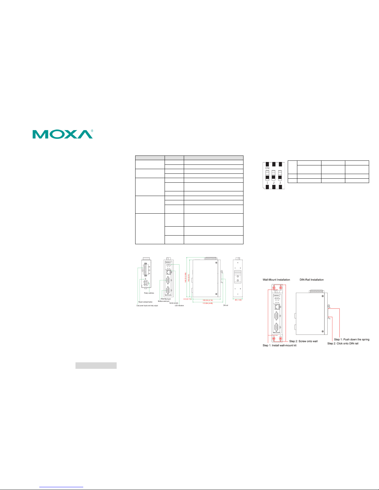
Hardware Introduction
LED Indicators
LED
Color
Function
PWR1
Green
Power is on
Off
Power is off
PWR2
Green
Power is on
Off
Power is off
Ready
Green
Gateway is operational
Red
Check Configu ration failed or Set
Parameter failed
Off
Power is off or fault condition exists
P1 TX/RX
(Modbus Seria l)
Green
Serial device is transmitting da ta
Orange
Serial device is receiving data
Off
No data is flowing to or from the
serial port
P2 Status
(PROFIBU S)
Green
Steady:
Gateway is waiting for data
exchange
Blinking: Data is exchanging
Orange
Steady: Configuration error
Blinking: Error in Parameter data
Off
PROFIBUS offline or Slave ID is
incorrect
The MGate 4101-MB-PBS and 4101I-MB-PBS both come with an
RJ45 to DB9 cable for connecting to a serial console.
Reset Button
The reset button is used to load factory defaults. Use a pointed
object such as a straightened paper clip to hold the reset button
down for five seconds. Release the reset button when the Ready
LED stops blinkin g.
Pull-high, Pull-low, and Terminator for RS-485
Remove the MGate 4101-MB-PBS’s top cover to adjust the DIP
switches for each serial port’s pull-high resistor, pull-low resistor,
and terminator.
SW
1 2 3
Pull-high
resistor
Pull-low
resistor
Terminator
ON
1 kΩ
1 kΩ
120 Ω
OFF
150 kΩ*
150 kΩ*
–*
*Default
Hardware Installation Procedure
STEP 1:
Connect the power adapter. Connect the 12-48 VDC
power line with the
MGate 4101-MB-PBS/4101I-MB-
PBS
series’ terminal block, or connect the
DIN rail power
supply with t he
MGate 4101-MB-PBS/4101I-MB-PBS
device’s termina l block.
STEP 2:
Use a
PROFIBUS cable to connect the unit to a
PROFIBUS
PLC
or other PROFIBUS master.
STEP 3:
Connect your device to the unit’s serial port.
STEP 4:
Attach the device to a DIN rail or the wall. The MGate
4101
-MB-PBS/4101I-MB-PBS series is designed to be
attached to a DIN rail or mounted on a wall. For DIN rail
mounting, push down the spring and properly attach it to
the
DIN rail until it snaps into pla ce. For wall
mounting,
install the wall mount kit (optional) first, and then screw
the device onto th e wall. The follo wing figure il lustrates
the two
mounting options:
Page 2
– 4 – – 5 – – 6 –
www.moxa.com/support
The Americas:
+1-714-528-6777 (toll-free: 1-888-669-2872)
Europe:
+49-89-3 70 03 99-0
Asia-Pacific:
+886-2-8919-1230
China:
+86-21-5258-9955 (toll-free: 800-820-5036)
2014 Moxa Inc. All rights reserved.
Software Installation Information
To install MGate Manager, insert the MGate Documentation &
Software CD into your PC’s CD-ROM d rive. Once the in stallation
window opens, click the Installation button and follow the onscreen
instructions. For more detailed information about MGate Manager,
click the Documents button and select the MGate 4101-MB-PBS
User’s Manual.
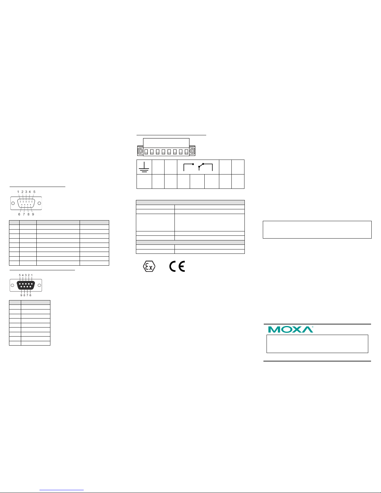
Pin Assignments
Modbus Serial Port (Male DB9)
Pin
RS-232
RS-422/RS-485 (4W)
RS-485 (2W)
1
DCD
TxD-(A)
–
2
RXD
TxD+(B)
– 3 TXD
RxD+(B)
Data+(B)
4
DTR
RxD-(A)
Data-(A)
5
GND
GND
GND
6
DSR – –
7
RTS – –
8
CTS – – 9 – – –
PROFIBUS Serial Port (Female DB9)
PIN
Signal Name
1 – 2 – 3
PROFIBUS D+
4
RTS
5
Signal common
6
5V 7 –
8
PROFIBUS D-
9
–
Power Input and Relay Output Pinouts
V2+ V2-
V1+ V1-
Shielded
Ground
DC
Power
Input 2
DC
Power
Input 2
N.O.
Common
N.C.
DC
Power
Input 1
DC
Power
Input 1
Specifications
Power Requirements
Power Input
12 to 48 VDC
Power Consumption
375 mA @ 12 VDC, 140 mA @ 48 VDC
Operating
Temperature
Standard Model:
0 to 60°C (32 to 140°F)
Wide Temp. Model:
-40 to 75°C (-40 to 167°F)
Operating Humid ity
5 to 95% RH
Dimensions
36 x 105 x 140 mm (1.42 x 4.13 x 5.51 in)
Reliability
Alert Tools
Built-in buzzer and RTC
MTBF
513,139 hrs
1. ATEX Certificate No.: DEMKO 14 ATEX 1311X
2. Protection Method: ε II 3G Ex nA nC IIC T4 Gc
3. IECEx Certificate No: IECEx UL 14.0065X
4. Stand ards: EN 60079 -0:2012+A11:2013; EN 60079-15:2010;
IEC 60079-0 Ed.6; IEC 60079-15 Ed.4.
5. Conditions of safe usage:
• This equipment shall only be used in an area of not more
than pollution degree 2, as def ined in IEC/EN 60 664-1.
• This equipment shall be installed in an enclosure that
provides a degree of protection not less than IP54 in
accordance with IEC/EN 60079-15. The enclosure should
only be accessible by using a tool (wren ch, screw driver,
etc.).
• Transient protection shall be provided that is set at a level
not exceeding 140% of the peak rated voltage value at the
equipment’s power supply terminals.
• The Terminal Blo ck (J1) is suita ble for 28-12 AWG
(0.0804-3.31 mm
2
), and a torque of 4.5 lb-in (0.509 N-m).
The input termin al cable size is sp ecified as 14 AWG (2.1
mm
2
).
• Terminal blocks mu st not accommodate more than one
individual conductor at a clamping point.
• Conductors suitable for use in an ambient temperature of
84°C must be used for the Power Supply Terminal.
6. Ambient Temperature:
-40°C ≤ Ta ≤ +75°C for MGate 4 101X-MB-PBS-T mode ls;
-10°C ≤ Ta ≤ +60°C for MGate 4 101X-MB-PBS models.
Terminal Block Torque Value and Wire Gauge :
• Terminal block Header (J1)—Cat. No. 5EHDRM-08P,
manufactured by Dinkle Enterprise Co., Ltd. Rated 300 V, 15 A,
105°C, FW-1.
• Terminal block P lug—Cat. No. 5ESDV-04P, manufactured by
Dinkle Enterprise Co., Ltd. Rated 300 V, 15 A, 105°C, FW-2,
suitable for 28 -12 AWG wire size, and torque of 4.5 lb-in.
• The cross sectional area of the earthing conductors shall be
3.31-0.0804 mm² (28-12 AWG).
• The earthing conductor shall be at least equal to 14 AWG (2.1
mm²).
Moxa Inc.
Fl. 4, No. 135, Lane 235, Baoqiao Rd.
Xindian Dist., New Taipei Cit y, 23145
Taiwan, R.O .C.
 Loading...