

Page 1

P/N: 1802000100010
ME-10-T
Quick Installation Guide
1-slot chassis
Edition 1.1, May 2017
Technical Support Contact Information
www.moxa.com/support
Moxa Americas:
Toll
-free: 1-888-669-2872
Tel:
1-714-528-6777
Fax:
1-714-528-6778
Moxa China (Shanghai office):
Toll
-free: 800-820-5036
Tel:
+86-21-5258-9955
Fax:
+86-21-5258-5505
Moxa Europe:
Tel:
+49-89-3 70 03 99-0
Fax:
+49-89-3 70 03 99-99
Moxa Asia-Pacific:
Tel:
+886-2-8919-1230
Fax:
+886-2-8919-1231
Moxa India:
Tel:
+91-80-4172-9088
Fax:
+91-80-4132-1045
2017 Moxa Inc. All rights reserved.
Page 2
- 2 -
Introduction
Overview
Moxa’s NRack System includes the ME-10-T, which is a 1-slot chassis for
selected Moxa media converter slide-in modules. The ME-10-T allows
network administrators to connect various copper and fiber-optic network
media over different protocols. The ME-10-T provides installation space
for up to 1-slot media converter slide-in modules at the front of the unit.
Package Checklist
The Moxa ME-10-T products are shipped with the following items:
Standard Accessories
• ME-10-T x 1
• Quick installation guide (printed)
• Warranty card
NOTE
If any of these items are missing or damaged, please contact
your customer service representative for assistance.
Features
• Redundant 24 VDC (12 to 48 VDC) power inputs, DIN-rail or panel
mountable
• Relay Output alarm for when a port breaks or the power fails
• Operating temperature range from -40 to 75°C (T models)
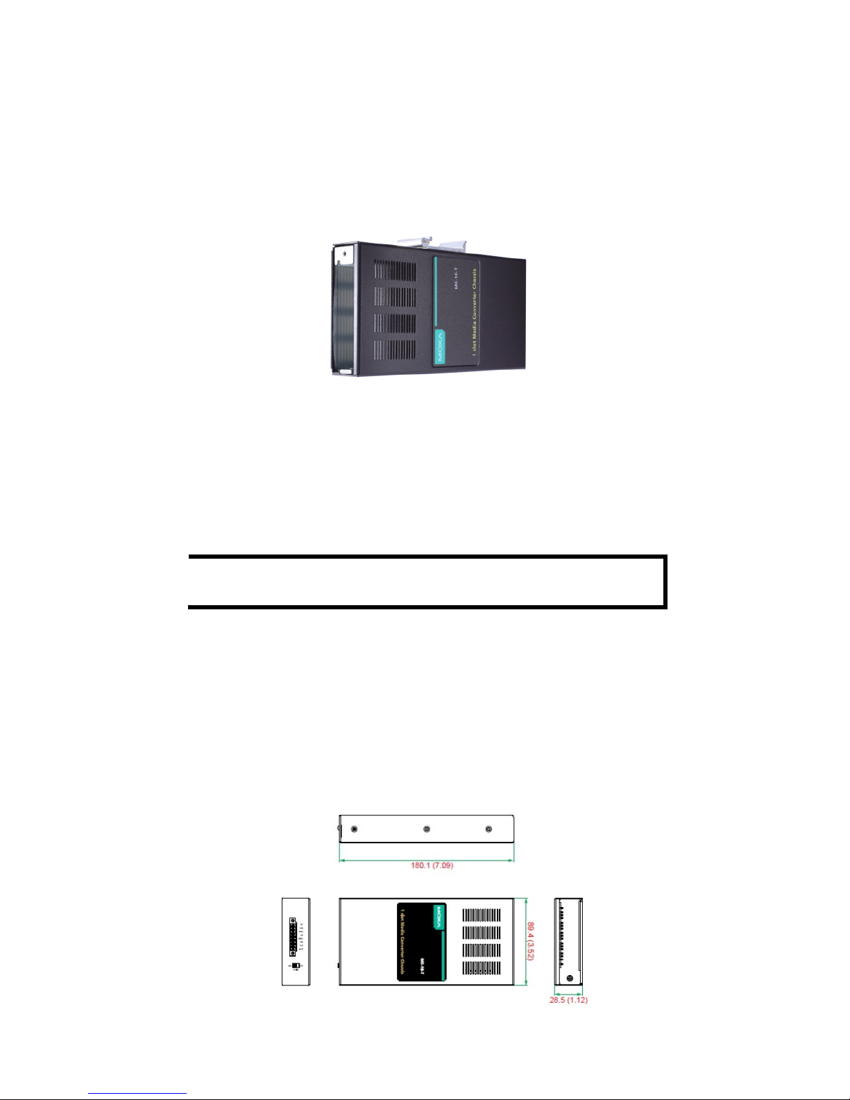
Mounting Dimensions
Page 3

- 3 -
DIN-Rail Mounting
The aluminum DIN-rail attachment plate should be fixed to the back panel
of the ME-10-T when you take it out of the box. If you need to reattach
the DIN-rail attachment plate to the ME-10-T, make sure the stiff metal
spring is situated at the top.
Wiring Requirements
ATTENTION
Safety First!
•
Be sure to disconnect the power cord before installing
and/or wiring your Moxa ME
-10-T.
•
Calculate the maximum possible current allowed in each
power wire and common
wire. Observe all electrical codes
dictating the maximum current allowed for each wire size.
•
If the current goes above the allowed maximum, the
wiring could overheat, causing serious damage to your
equipment.
• Use separate paths to route wiring for power and the devices. If
power wiring and device wiring paths must cross, make sure the wires are
perpendicular at the intersection point.
• Do not run signal or communications wiring and power wiring in
the same wire conduit. To avoid interference, wires with different signal
characteristics should be routed separately.
• You can use the type of signal transmitted through a wire to
determine which wires should be kept separate. The rule of thumb is that
wiring that shares similar electrical characteristics can be bundled
together.
• Keep input wiring and output wiring separated. We strongly advise
that you label the wiring to all the devices in the system.
Page 4
- 4 -
Grounding the ME-10-T
Grounding and wire routing help limit the effects of noise caused by
electromagnetic interference (EMI). Run the ground connection from the
ground screw to the grounding surface before connecting the devices.
ATTENTION
This product
should be mounted to a well-grounded mounting
surface, such as a metal panel.
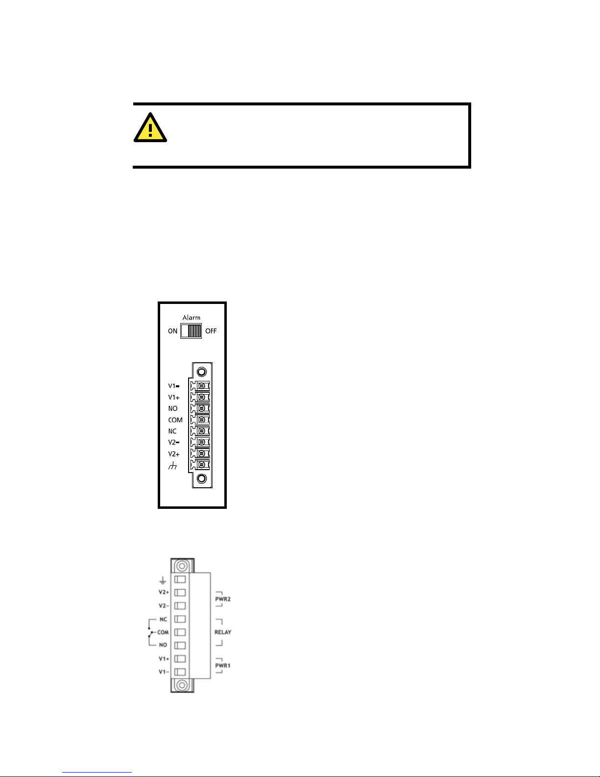
Wiring the Alarm Contact
The alarm contact is made up of the three middle contacts of the terminal
block on the ME-10-T’s top panel. Refer to the next section for detailed
instructions on how to connect the wires to the terminal block connector,
and how to attach the terminal block connector to the terminal block
receptor.
In this section, we explain the meaning of the three contacts used to
connect the alarm contact.
RELAY: The three middle contacts of the
8-contact terminal block connector are used to
detect both power faults and port faults. The two
wires attached to the fault contacts form an open
circuit when:
1. The ME-10-T has lost power from one of the DC
power inputs.
OR
2. One of the ports for which the corresponding
PORT ALARM Dip Switch is set to ON is not
properly connected.
If neither of these two conditions occurs, the fault
circuit will close.
Wiring the Redundant Power Inputs
STEP 1: Insert the negative/positive DC wires
into the V-/V+ terminals.
STEP 2: To keep the DC wires from pulling loose,
use a small flat-blade screwdriver to tighten the
wire-clamp screws on the front of the terminal
block connector.
STEP 3: Insert the plastic terminal block
connector prongs into the terminal block
receptor.
Page 5

- 5 -
ATTENTION
Before
connecting the ME-10-T to the DC power inputs, make
sure the DC power source voltage is stable.
Slide-in Modules Installation
Installing the Media Converter Slide-in Modules
The instructions to install the media converter slide-in modules into the
ME-10-T chassis are as follows:
1. The slide-in modules can be installed in an empty slot of the
chassis.
2. Before installing a slide-in module, make sure the front plate has
been removed.
3. Align the slide-in module with the chassis installation slot so that
the panel fastener screw is at the top of the module.
4. Carefully insert the slide-in module into the slot while aligning the
module’s circuit board as per the installation guide.
5. Ensure that the slide-in module is firmly fitted inside the chassis.
6. Push in and rotate the attached panel fastener screw clockwise to
secure the module to the chassis.
Replacing the Media Converter Slide-in Modules
To replace a media converter slide-in module in the ME-10-T chassis:
1. The media converter slide-in module can be hot-swapped, which
means the chassis doesn’t have to power off during the installation or
when the module is being removed.
2. Remove the slide-in module that needs to be replaced by loosening
the panel fastener screw that secures the module to the chassis. Slide the
module out from the chassis.
3. Align the replacement slide-in module with the chassis installation
slot so that the panel fastener screw is at the top of the module.
4. Carefully insert the slide-in module into the slot while aligning the
module’s circuit board as per the installation guide.
5. Ensure the slide-in module is firmly fitted inside the chassis.
6. Push in and rotate the attached panel fastener screw clockwise to
secure the module to the chassis.
Page 6

- 6 -
Specifications
Physical Characteristics
Housing
SECC (1.2 mm)
Dimensions
180.1 x 89.4 x 28.5 mm (7.09 x 3.52 x 1.12 in)
Weight
0.53 kb (1.17 lb)
Number of Slots
1 slot on the front for slide-in modules
Environmental Limits
Operating
Temperature
-40 to 75°C (-40 to 167°F)
Storage
Temperature
-40 to 85°C (-40 to 185°F)
Ambient Relative
Humidity
5 to 95% (non-condensing)
Power Requirements
Input Voltage
12 to 48 VDC
Input Current
0.43 A @ 12 VDC
Standards and Certifications
Safety
UL 60950-1, EN 60950-1
EMC
CE, FCC
EMI
EN 55032 Class A, FCC Part 15 Subpart B Class A
EMS EN 61000-4-2 ESD: Contact: 4 kV; Air: 8 kV
EN 61000-4-3 RS: 80 MHz to 1 GHz: 3 V/m
EN 61000-4-4 EFT: Power: 1 kV
EN 61000-4-5 Surge: Power: 1 kV
EN 61000-4-6 CS: 150 kHz to 80 MHz: 3 V/m
Green Product
RoHS, CRoHS, WEEE
MTBF (mean time between failures)
Time
1,055,112 hrs.
Standard
Telcordia (Bellcore), GB
Warranty
Warranty Period
5 years
Details
See www.moxa.com/warranty
 Loading...