

Page 1

MD-219 Hardware Manual
First Edition, October 2014
www.moxa.com/product
© 2014 Moxa Inc. All rights reserved.
Page 2

MD-219 Hardware Manual
The software described in this manual is furnished under a license agreement and may be used only in accordance with
the terms of that agreement.
Copyright Notice
© 2014 Moxa Inc. All rights reserved.
Trademarks
The MOXA logo is a registered trademark of Moxa Inc.
All other trademarks or registered marks in this manual belong to their respective manufacturers.
Disclaimer
Information in this document is subject to change without notice and does not represent a commitment on the part of
Moxa.
Moxa provides this document as is, without warranty of any kind, either expressed or implied, including, but not limited
to, its particular purpose. Moxa reserves the right to make improvements and/or changes to this manual, or to the
products and/or the programs described in this manual, at any time.
Information provided in this manual is intended to be accurate and reliable. However, Moxa assumes no responsibility for
its use, or for any infringements on the rights of third parties that may result from its use.
This product might include unintentional technical or typographical errors. Changes are periodically made to the
information herein to correct such errors, and these changes are incorporated into new editions of the publication.
Technical Support Contact Information
www.moxa.com/support
Moxa Americas
Toll
-free: 1-888-669-2872
Tel:
+1-714-528-6777
Fax:
+1-714-528-6778
Moxa China (Shanghai office)
Toll
-free: 800-820-5036
Tel:
+86-21-5258-9955
Fax:
+86-21-5258-5505
Moxa Europe
Tel:
+49-89-3 70 03 99-0
Fax: +49-89-3 70 03 99-99
Moxa Asia
-Pacific
Tel:
+886-2-8919-1230
Fax: +886-2-8919-1231
Moxa India
Tel:
+91-80-4172-9088
Fax:
+91-80-4132-1045
Page 3

Table of Contents
1. Introduction ...................................................................................................................................... 1-1
Overview ........................................................................................................................................... 1-2
Ordering Information .......................................................................................................................... 1-2
Package Checklist ............................................................................................................................... 1-2
Product Features ................................................................................................................................ 1-3
MD-219 Hardware Specifications .......................................................................................................... 1-3
2. Hardware Introduction...................................................................................................................... 2-1
Appearance and Layout ....................................................................................................................... 2-2
Dimensions ........................................................................................................................................ 2-3
SavvyTouch Display Control Buttons ..................................................................................................... 2-3
3. Hardware Connection Description ..................................................................................................... 3-1
Placement Guidelines .......................................................................................................................... 3-2
Installation Notes ............................................................................................................................... 3-2
Desktop Mounting ....................................................................................................................... 3-3
Panel Mounting ........................................................................................................................... 3-4
VESA Mounting ........................................................................................................................... 3-5
Safety Precautions .............................................................................................................................. 3-6
Grounding the MD-219 Series .............................................................................................................. 3-6
Powering on/off the MD-219 Series ....................................................................................................... 3-7
SavvyTouch Display Control Buttons .............................................................................................. 3-7
Connecting Data Transmission Cables ................................................................................................... 3-9
Connecting the MD-219 to a Computer .......................................................................................... 3-9
Enabling the Touch Screen Interface (Z models only) .............................................................................. 3-9
Connecting Video Input Cables ........................................................................................................... 3-10
Connecting the Built-in Buzzer............................................................................................................ 3-11
4. Touch Function .................................................................................................................................. 4-1
Installing Touch Function Driver ........................................................................................................... 4-2
Performing Screen Calibration .............................................................................................................. 4-7
5. Display Control Interface .................................................................................................................. 5-1
Connecting to the UART Control Interface .............................................................................................. 5-2
UART Command Format ...................................................................................................................... 5-4
Command Format Details ............................................................................................................. 5-4
Downloading RGB Files ........................................................................................................................ 5-6
VGA ........................................................................................................................................... 5-6
DVI ........................................................................................................................................... 5-6
A. Regulatory Approval Statement ........................................................................................................ A-1
B. On-Screen Display (OSD) Controls .................................................................................................... B-1
Opening the Configuration Screen ......................................................................................................... B-2
OSD Menu Map and Items Explained ..................................................................................................... B-2
Source – Auto Source .................................................................................................................. B-2
Image Setting – Auto Setup ......................................................................................................... B-2
Image Setting – Display ............................................................................................................... B-3
Color Mode – Color Temperature ................................................................................................... B-3
Color Mode – Color Temperature – User ......................................................................................... B-3
Management – Communication ..................................................................................................... B-4
OSD Misc – OSD position .............................................................................................................. B-4
OSD Misc – Language .................................................................................................................. B-5
OSD Misc – Preset Save ............................................................................................................... B-5
OSD Misc – OSD Lock Mode .......................................................................................................... B-5
Service ...................................................................................................................................... B-6
Service – Test Pattern .................................................................................................................. B-6
C. Display UART Commands .................................................................................................................. C-1
OSD Control Command ........................................................................................................................ C-2
BRI (Brightness Minimum Value) ................................................................................................... C-2
BRL (Set LED Brightness of Touch Keypad) ..................................................................................... C-2
BRM (Brightness Maximum Value) ................................................................................................. C-2
BRT (User Brightness Control) ...................................................................................................... C-2
BRU (Glass Display Control-Brightness Button) ............................................................................... C-3
BZZ (Buzzer Control) ................................................................................................................... C-3
DLN (Download ECDIS RGB File) ................................................................................................... C-3
DL? (ECDIS RGB Package Query) .................................................................................................. C-4
D2N (Download ECDIS RGB File (Second)) ..................................................................................... C-4
D2? (ECDIS RGB Package Query (Second)) .................................................................................... C-4
ETC (Elapsed Time Counter Query) ................................................................................................ C-4
GMB (Glass Display Control - Minimum Brightness) ......................................................................... C-5
Page 4

POT (Potentiometer Control) ......................................................................................................... C-5
SWI (Scalar Firmware Version Query) ............................................................................................ C-5
SWK (Touch Keypad Firmware Version Query) ................................................................................ C-5
ADF (AC Input Power Detect Function) ........................................................................................... C-5
AD? (Query AC Input Power Detect Function Status) ........................................................................ C-6
DDF (DC Input Power Detect Function) .......................................................................................... C-6
DD? (Query DC Input Power Detect Function Status) ....................................................................... C-6
BLI (Brightness Control) ............................................................................................................... C-6
DUF (Disable UART Command Function) ......................................................................................... C-7
EMS (ECDIS Mode Select) ............................................................................................................ C-7
CT? (Current Temperature Query) ................................................................................................. C-8
SS? (System Status Query) .......................................................................................................... C-8
MCC (OSD Control Command) ...................................................................................................... C-8
Page 5

1
1. Introduction
The MD-219 series displays are designed to fit the great demands of the marine industry. The 19-inch wide
viewable image size with 5:4 aspect ratio and 1280 x 1024 pixel resolution make the displays ideal for a variety
of marine applications. With full range dimming, optical bonding (optional), and wide angle viewing, these
computer display terminals meet required marine standards and are perfectly suited for a variety of marine
applications, both indoors and outdoors.
These displays use either AC or DC power inputs, simplifying the installation of the displays at field sites.
MD-219 displays are compliant with a wide variety of industrial marine standards, including IEC 60945, DNV,
and IACS-E10, lending greater credence to their suitability for maritime operations.
The following topics are covered in this chapter:
Overview
Ordering Information
Package Checklist
Product Features
MD-219 Hardware Specifications
Page 6

MD-219 Hardware Manual Introduction
1-2
Overview
The MD-219 Series is the 19-inch version of our marine display series. Designed for durably reliable service as
an ECDIS (Electronic Chart Display and Information System) display component, the MD-219 Series has a 5:4
aspect ratio, alongside full range dimming and optional optical bonding, making the displays well-suited not
only for ECDIS applications, but for a variety of other bridge applications, as well.
The MD-219 Series features both AC and DC power inputs, and may be conveniently installed on any bridge,
without the need for extra hardware.
Moxa’s marine displays are compliant with the most important industrial marine standards, including IEC
60945, DNV, and IACS-E10, giving strong assurance of their suitability for marine applications.
Ordering Information
Available Models
MD-219X: 19-inch, 5:4 aspect ratio display (1280x1024), LED backlight, DVI-D/VGA, RS-232 & RS-422/485
serial ports, AC/DC dual power
MD-219Z: 19-inch, 5:4 aspect ratio display (1280x1024), projected capacitive multi-touch, LED backlight,
DVI-D/VGA, RS-232 & RS-422/485 serial ports, AC/DC dual power
Optional Accessories (can be purchased separately)
• Desktop mounting kit
• Panel mounting clamps
• VESA mounting kit
Package Checklist
Each model is shipped with the following items:
• MD-219 display
• VGA cable
• DVI-D cable
• 2-pin terminal block x 1
• 5-pin terminal block x 2
• Documentation and software CD
• Quick installation guide (printed)
• Warranty card
NOTE
Please notify your sales
representative if any of the above items are missing or damaged.
Page 7

MD-219 Hardware Manual Introduction
1-3
Product Features
The MD-219 display has the following features:
• 19-inch display
• Color calibrated for ECDIS compliance
• Fanless design
• SavvyTouch display controls
• RS-232 and RS-422/485 serial ports for sending UART commands to configure display settings
• Dual AC/DC power supply units
• Optically bonded and touch panel models available on request
MD-219 Hardware Specifications
Display
Panel Size:
19” viewable image size
Panel
Type: MVA
Aspect Ratio:
5:4
Pixels:
1280 x 1024 (SXGA)
Response Time:
20 ms (gray to gray)
Contrast Ratio:
2000:1
Light Intensity:
300 cd/m2
Viewing Angles:
178˚/178˚
Active Display Area:
376.32 (H) x 301.06 (V) mm
Max Colors:
16.7M / 8-bit color
Display Interface:
VGA input x 1, DVI-D input x 1
Resolution:
• VGA: 640 x 480
• SVGA: 800 x 600
• XGA: 1024 x 768
•
XGA+: 1152 x 864
•
WXGA: 1280 x 768
• SXGA: 1280 x 1024
Serial Interface
Serial Standards:
1 RS-232 port (DB9), 1 RS-422/485 port (terminal block)
Optical Isolation Protection:
4 kV
Serial Signals
RS
-232: TxD, RxD, DTR, DSR, RTS, CTS, DCD, GND
RS
-422: TxD+, TxD-, RxD+, RxD-, GND
RS
-485-2w: Data+, Data-, GND
Front Panel
LEDs:
MENU, Brightness, INFO, ECDIS, Day/Dusk/Night
Smart OSD:
Yes
Physical Characteristics
Housing:
Aluminum sheet metal
Weight:
7.8 kg
Dimensions:
429 x 387 x 75 mm (16.89 x 15.24 x 2.95in)
Mounting:
VESA, panel, and dektop (temporary)
Environmental Limits
Operating Temperature:
-15 to 55°C (5 to 131°F)
Storage Temperature:
-20 to 60°C (-4 to 140°F)
Ambient Relative Humidity: 5 to 95% (non-condensing)
Page 8

MD-219 Hardware Manual Introduction
1-4
IP Rating:
• Front: IP 54
• Rear: IP 22
Anti
-Vibration:
• 0.7 g @ DNV 2.4 (Class A), sine wave, 2
-100 Hz, 1 Oct./min., 1.5 hr per axis
• 1 Grms @ DNV 2.4, random wave, 3
-100 Hz, 2.5 hr per axis
• 2.1 g @ DNV 2.4 (Class C), sine wave, 2
-50 Hz, 1 Oct./min., 1.5 hr per axis
Power Requirements
Input Voltage:
•
DC: 24 VDC (with tolerance from 18 to 30 VDC, 2-pin terminal block)
• AC: 100 to 240 VAC
Power Consumption:
40 W (max.)
Standards and Certifications
Safety:
UL/cUL, CCC
EMC:
EN 55022 Class B, EN 55024-4-2, EN 55024-4-3, EN 55024-4-4, FCC Part 15 Subpart B Class A
Marine Standard:
IEC-60945 4th, IEC-61162, IEC-61174
Marine Type Approval:
DNV 2.4 and IACS E10, ABS
Green Product:
RoHS, cRoHS, WEEE
Warranty
Warranty
Period: 1 year
Details:
See www.moxa.com/warranty
We recommend taking the following precautions to minimize heat build-up within the display:
• Position the display within ±40° of the vertical
• If (a) the display is not positioned within ±40° of the vertical, (b) the ambient temperature exceeds 25°C,
or (c) the display is used in a location with minimal ventilation, then install an external fan to increase
airflow upwards through the chassis
Important Safety Precaution:
Even though the display is rated to operate within the IEC 60945standard of -15 to 55°C for bridge applications,
it is best to ensure that the ambient temperature does not exceed 25°C. Doing so will significantly increase the
lifespan of your display and reduce service costs.
Page 9

2
2. Hardware Introduction
The MD-219 Series display is compact, well-designed, and ruggedized for marine applications. The intelligent
SavvyTouch display control buttons allow you to see control buttons easily in low light environments and
identify system hardware failures easily. Multiple serial ports allow you to configure display parameters, and
the reliable and stable hardware platform lets you devote your attention to developing your applications.
The following topics are covered in this chapter:
Appearance and Layout
Dimensions
SavvyTouch Display Control Buttons
Page 10

MD-219 Hardware Manual Hardware Introduction
2-2
Appearance and Layout
Page 11
MD-219 Hardware Manual Hardware Introduction
2-3
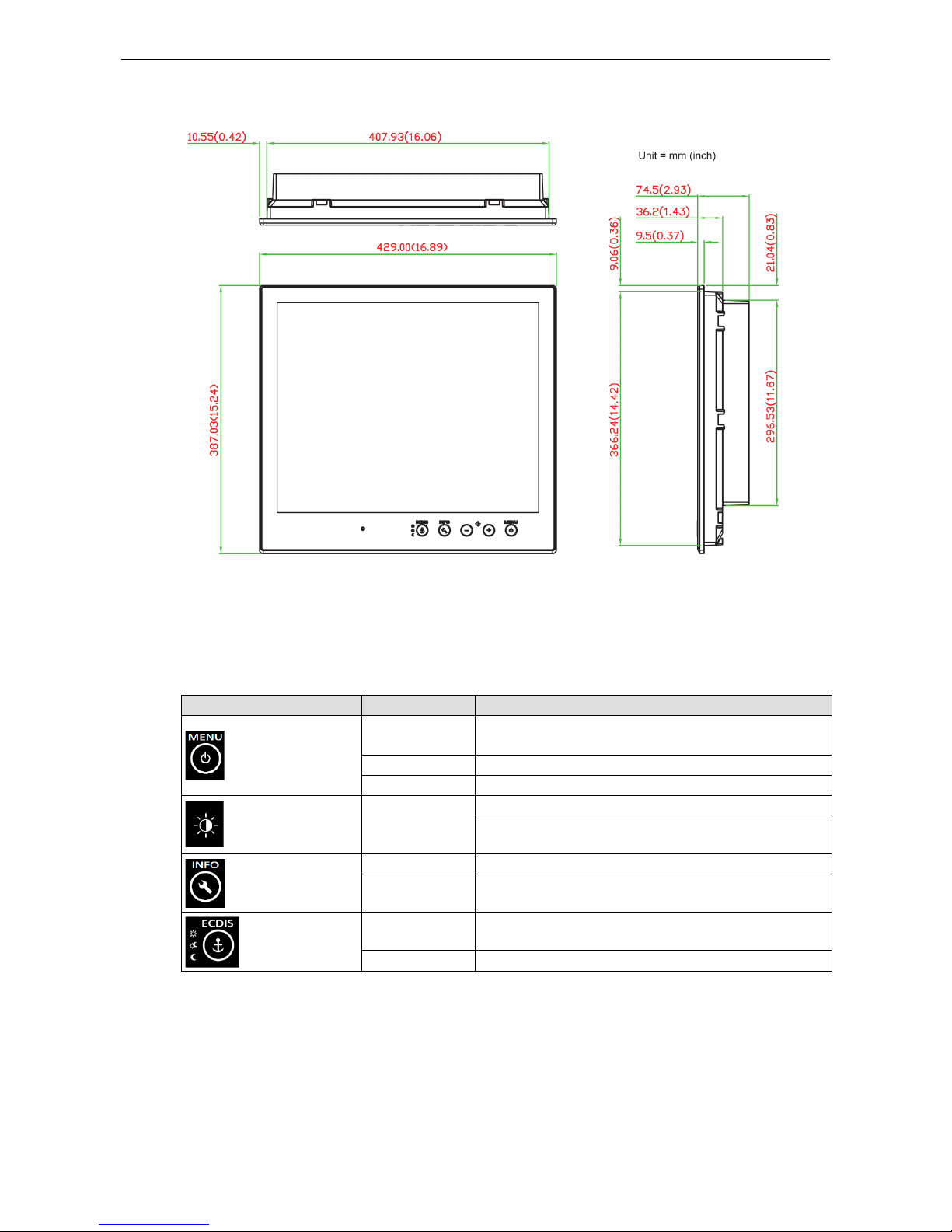
Dimensions
SavvyTouch Display Control Buttons
The MD-219 comes with SavvyTouch display control buttons located at the lower right corner of the front
surface. These intelligent buttons will light up automatically when your fingers draw near. Refer to the following
table for the function of each button.
Name Display Color Control Function / Color Legend
Menu/Power
Green
Display is powered on and functioning normally.
Touch the button to show the OSD settings menu.
Red No input signal detected. Display on standby.
Off Power is down and the display is off.
Brightness
White
+: To increase brightness of panel
-: To decrease brightness of panel
Info
Off AC/DC power fuSnctioning normally
Red AC/DC power error
Display mode
White Switch between DAY/DUSK/NIGHT brightness modes
Off Panel brightness out of default range
Page 12

3
3. Hardware Connection Description
In this chapter, we show how to correctly install the MD-219 display using various mounting kits, how to
connect the different types of cables, and how to enable functions.
The following topics are covered in this chapter:
Placement Guidelines
Installation Notes
Desktop Mounting
Panel Mounting
VESA Mounting
Safety Precautions
Grounding the MD-219 Series
Powering on/off the MD-219 Series
SavvyTouch Display Control Buttons
Connecting Data Transmission Cables
Connecting the MD-219 to a Computer
Enabling the Touch Screen Interface (Z models only)
Connecting Video Input Cables
Connecting the Built-in Buzzer
Page 13
MD-219 Hardware Manual Hardware Connection Description
3-2
Placement Guidelines
Before installing and mounting the MD-219 display, please read the following notes:
1. The MD-219 series is designed for various installation or mounting methods, including desktop mounting,
panel mounting, and VESA mounting. Please refer to the relevant mechanical drawings in the next sections.
2. Good ventilation is necessary to prolong the life of the product. The chassis heat-sink area MUST keep clear
from other heat generating items, or the motherboard could be damaged. The minimum distance is 150
mm.
3. Keep sufficient space for ventilation improvement, cable inlet or wiring installation, and maintenance
purposes.
4. DO NOT install the unit in a horizontal position (laying down), since the heat from inside the unit will not
dissipate effectively, resulting in damage to the LCD panel. We recommend installing the unit in a vertical
position (±30 degrees) for better heat dissipation.
5. Exposure to extreme direct sunlight may cause a considerable increase in the temperature of the unit, and
under certain circumstances might cause the temperature to increase beyond the recommended value. Be
sure to keep this point in mind when planning the placement of bridge equipment (sun shades, distance
from the windows, ventilation, etc.).
6. Exposure to strong vibration or acoustic noise might affect functionality and expected lifetime. During
system assembly and installation, be sure to mount the display carefully to avoid exposure to amplified
vibrations.
7. For maximum safety, at least two people should work together to lift, place, and fasten the display to its
mounting point. Before you lift or move the display, first verify that any power to the system is turned off.
In addition, make sure you have prepared the correct screws for panel mounting.
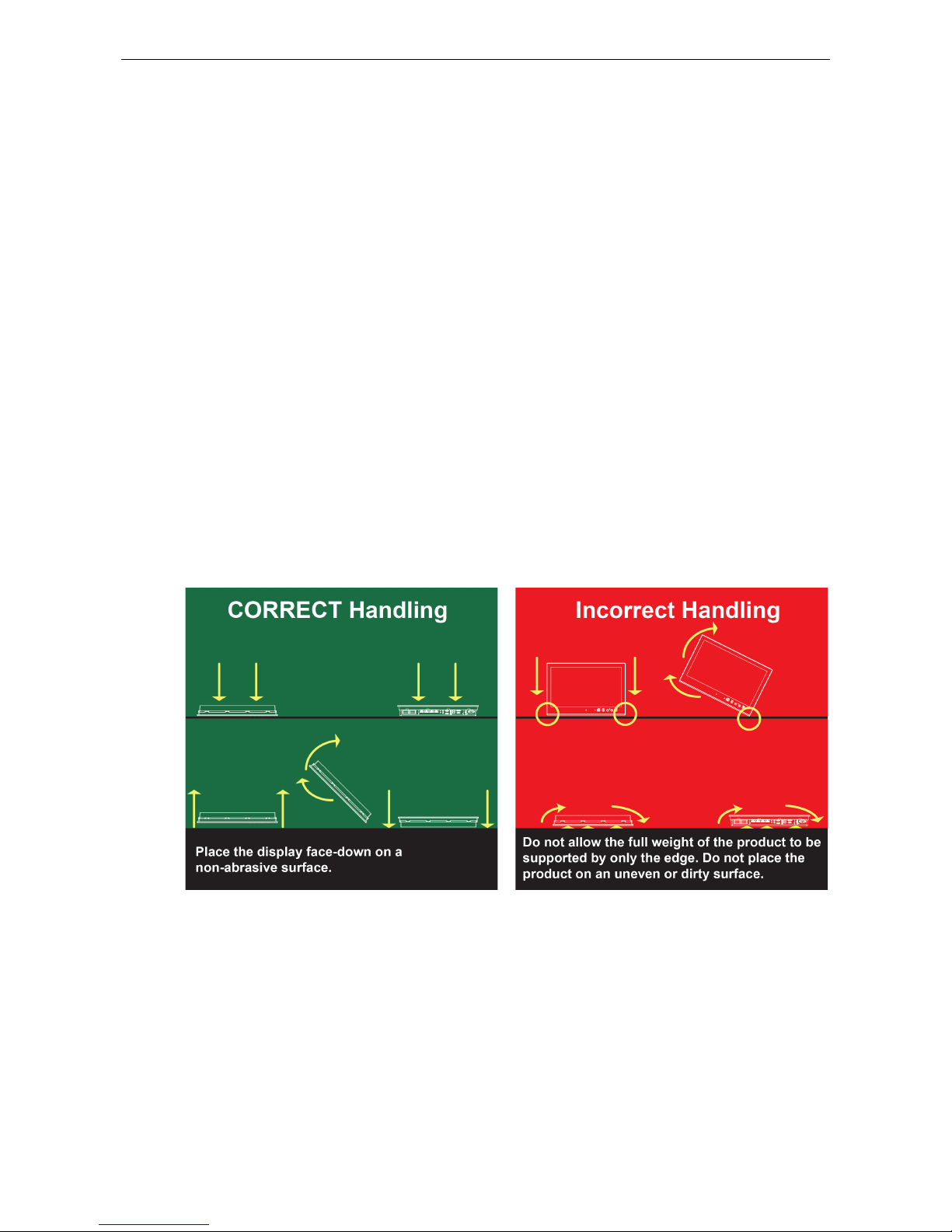
Installation Notes
Follow these steps when installing the MD-219:
1. Fasten the mounting kit on the display first, and then mount the display.
2. Connect cables (DVI-D, VGA, Power cord, etc).
3. Power on the MD-219 display, and then power on the computer.
Page 14
MD-219 Hardware Manual Hardware Connection Description
3-3
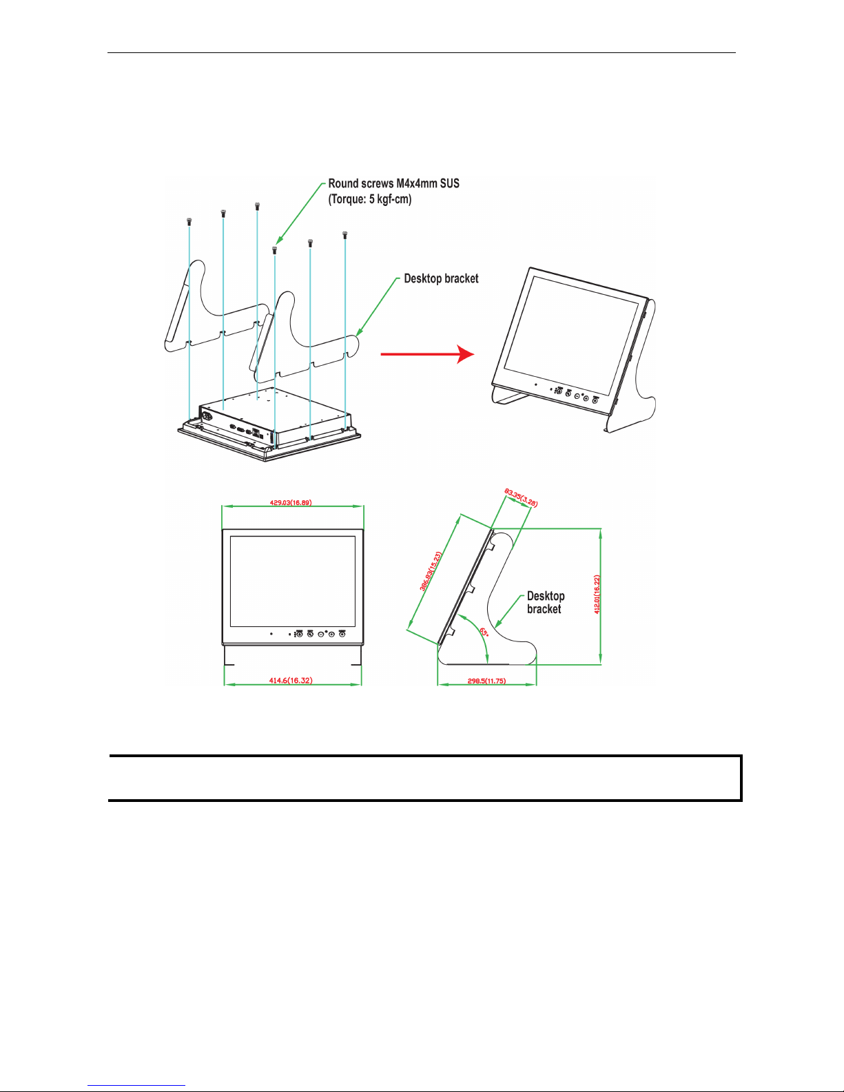
Desktop Mounting
The MD-219 comes with optional brackets that allow you to install it on a horizontal surface, such as a desktop.
Three round screws are required for each bracket. See the figure below for detailed screw specifications and
their torque values.
Place your MD-219 on a clean, flat, well-ventilated desktop. For better ventilation, leave some space between
the MD-219 Series and other equipment. Do not place equipment or objects on top of the MD-219, as this might
damage the display’s internal components.
NOTE
These desktop brackets are intended for temporary use when conducting lab tests, and are not intended to be
used in permanent deployments.
Page 15
MD-219 Hardware Manual Hardware Connection Description
3-4
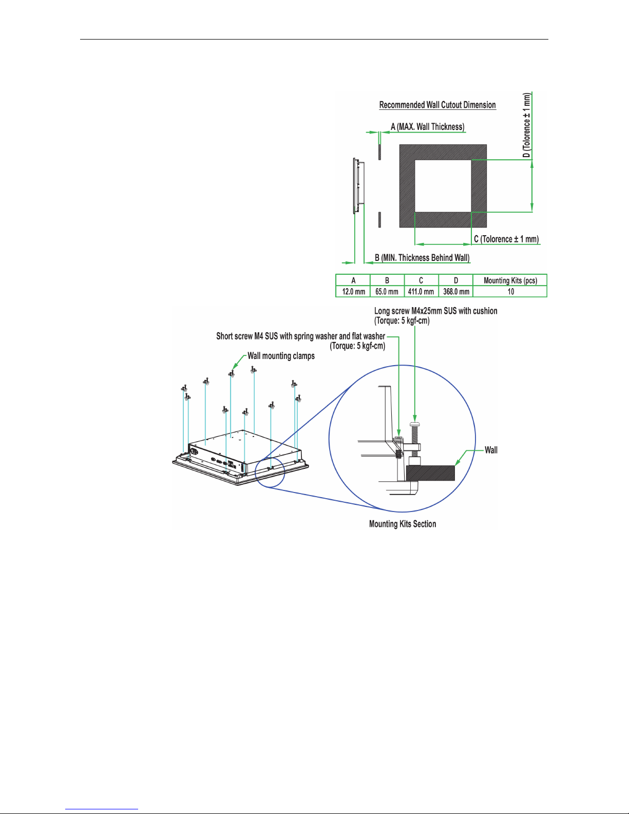
Panel Mounting
The
MD-219 Series comes with 14 optional clamp
mounts that allow for installation onto a wall (where
space has been cut out to accommodate the rest of
the hardware) or into computing stations where a
flush mount is desired. The maximum thickness
of the surface to wh
ich the display can be
clamped is 11 mm. For a secure mounting, all 14
clamps must be used. The clamp arms are fastened
into slots o
n all four sides of the MD-219. Use the
short M4 SUS
(stainless) screws to
fasten the clamp
arms to the MD
-219 mounting slot
s, as shown in the
magnified inset in the diagram just below. Next, use
the clamps to fasten the
display to its mounting
point; please note the torque value
s shown in the
figure inset
below.
Page 16

MD-219 Hardware Manual Hardware Connection Description
3-5
VESA Mounting
The MD
-219 Series also comes with an
optional VESA mounting kit. Six flat screws
and four round screws are required to fasten
the VESA mounting bracket. See the figure
below for detailed screw specifications and
torque values.
An additional four screws (not included
in
the kit) are required to mount the
display
on
a VESA rack. For this purpose, use M6
screws with a length between 10 and 12
mm.
Page 17
MD-219 Hardware Manual Hardware Connection Description
3-6
Safety Precautions
ATTENTION
Safety First!
Be sure to disconnect the power cord before ins
talling and/or wiring your MD-219 Series.
Wiring Caution!
Calculate the maximum possible current in each power wire and common wire. Observe all electrical codes
dictating the maximum current allowable for each wire size.
If the current goes above the
maximum ratings,
the wiring could overheat, causing serious damage to your equipment.
Temperature Caution!
Be careful when handling the unit. When the unit is plugged in, the internal components generate heat, and
consequently the outer casing may feel hot
to the touch.
We recommend taking the following precautions to minimize heat
build-up within the display:
•
Position the display within ±40° of the vertical.
•
Install an external fan to increase airflow upwards through the display if (a) the display is not
positioned
within ±40° of the vertical, (b) the ambient temperature exceeds 25°C, or (c) the display is used in a
location with minimal ventilation.
Important Safety Precaution
Even though the display is rated to operate within the
IEC 60945 standard of -15 to 55°C for marine
applications, it is best to ensure
that the ambient temperature does not exceed 25°C. Doing so will
increase the
life of your display and minimize service costs.
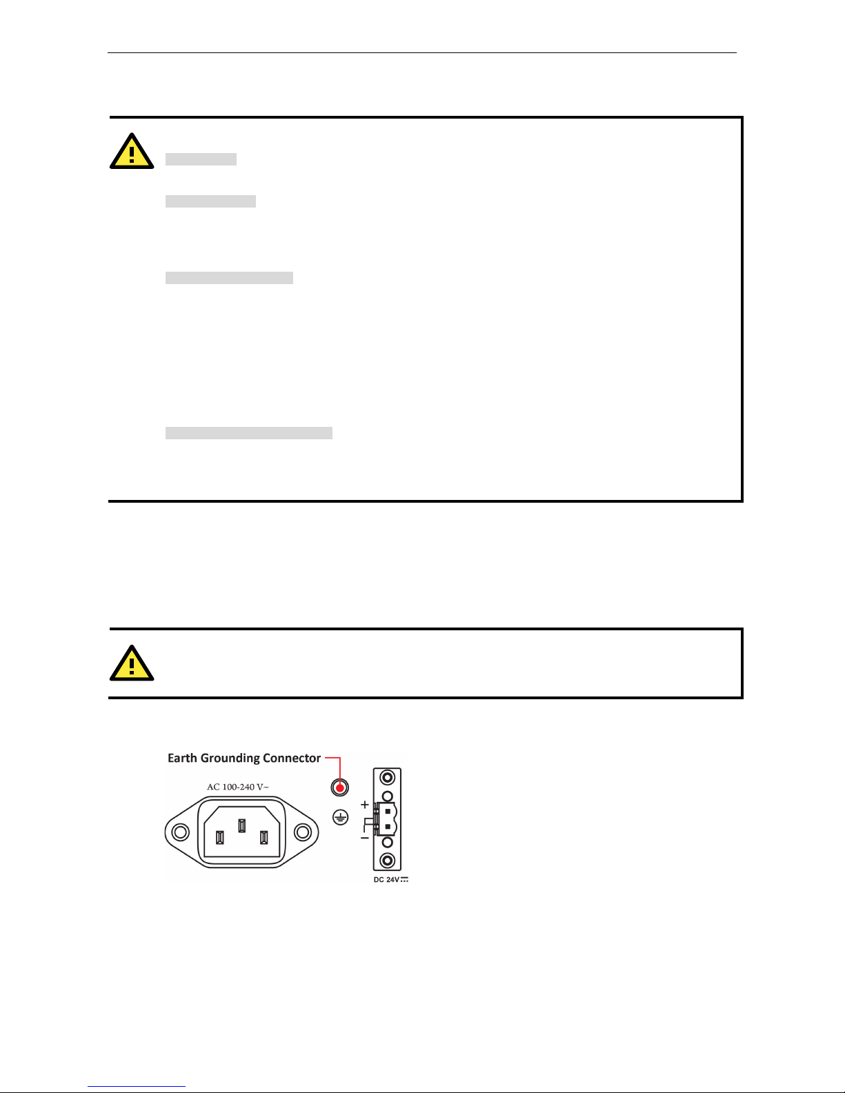
Grounding the MD-219 Series
Be sure to ground the MD-219 Series before powering it on. Grounding and wire routing help limit the effects
of noise due to electromagnetic interference (EMI). Run the ground connection from the ground screw to the
grounding surface prior to connecting the power.
ATTENTION
This product is intended to be mounted to a well
-grounded mounting surface, such as a metal panel.
Earth Ground: See the figure shown below for the location of the earth grounding connector. Connect the
grounding wire to an appropriate grounded metal surface.
Page 18

MD-219 Hardware Manual Hardware Connection Description
3-7
Powering on/off the MD-219 Series
To power on the MD-219 Series you may connect the Terminal Block to Power Jack Converter to the
MD-219 Series DC terminal block (located on the bottom surface) and then connect a power adapter; or,
alternatively, you may power the device with the AC power cord. Touch the MENU button (in the lower right
corner of the display panel) for 1 second or use a UART command (MCC-0x9F-Power Down/Up Display) to turn
on the display.
To power off the MD-219 Series, touch the MENU button for 4 seconds until the green LED light of the MENU
button turns off, or use a UART command (MCC-0x9F-Power Down/Up Display) to turn off the display.
NOTE
If the MD
-219 is powered using a DC converter, an “OFF
” message will appear when the INFO dialog displays
the AC power stat
us and vice versa. This will not affect the MD-219’s operation.
SavvyTouch Display Control Buttons
The MD-219 Series comes with five SavvyTouch display control buttons located on the front surface. These
intelligent controls will light up as your hand draws near the area of the screen where they are located.
MENU
To configure the panel display settings, open the on-screen display (OSD) configuration panel by pressing the
MENU button. The LCD panel will then display a configuration menu superimposed over the currently displayed
image. The MENU button is for opening and closing the OSD, and brightness buttons "+/-" for navigating the
OSD menus.
The MENU button operates like a power button in that it enables users to turn the display on and off. When you
press the button for 1 second, the display will power on and indicate the status with a solid green color. To
power off the MD-219, press and hold the MENU button for 4 seconds to turn the display and MENU button LED
to OFF. On the OSD MAIN MENU page, use the same action to confirm or exit.
Page 19

MD-219 Hardware Manual Hardware Connection Description
3-8
Brightness
Two brightness buttons are available for brightness control. Press the + button to increase the brightness of the
panel; press the – button to decrease the brightness of the panel. On the OSD MAIN MENU page, the + and -
buttons are used to increment and decrement values, and to move up and down between options.
INFO
The INFO button indicates the display status for power components, including AC and DC. “ON” indicates that
the display is working well. An OFF message will be shown when the AC or DC power is not working.
System Status
AC Input Power ON
DC Input Power ON
System Status
AC Input Power ON
DC Input Power OFF
NOTE
If the
MD-219 is powered using a DC converter, an “OFF
” message will appear when the INFO dialog displays
the AC power status
and vice versa. This will not affect the MD-219’s operation.
ECDIS
The ECDIS button is specially designed to support ECDIS for maritime applications. Touch the button to switch
between the three different brightness modes (DAY, DUSK, and Night).
ECDIS Mode
DAY
DUSK
NIGHT
NOTE
Pressing the ECDIS
button will override the display's current brightness setting.
Page 20

MD-219 Hardware Manual Hardware Connection Description
3-9
Connecting Data Transmission Cables
Connecting the MD-219 to a Computer
Use a serial cable to connect your computer to the display's serial port. The serial port uses a male DB9
connector and terminal block. It can be configured by a UART command or OSD control. Only one of the three
interfaces (RS-232/422/485) can be used at the same time. The pin assignments are shown in the
following diagrams:
DB9 Male Port
RS
-232 (DB9 Male) Pinouts
Pin RS-232
1 DCD
2 RxD
3 TxD
4 DTR
5 GND
6 DSR
7 RTS
8 CTS
Terminal Block Port
RS
-422/485 (Terminal Block) Pinouts
Pin
RS-422
RS-485 (2-wire)
1 RxDB(+) TDp(+)
2 RxDA(-) TDn(-)
3 TxDB(+) RDp(+)
4 TxDA(-) RDn(-)
5 GND GND
Configuring the RS-232/422/485 Serial Ports
For configuring the RS-232/422/485 serial port, please see Appendix B: On-Screen Display (OSD)
Controls and Appendix C: Display UART Commands.
Enabling the Touch Screen Interface (Z models
only)
The MD-219Z model comes with a USB port on its bottom panel. This USB port is used to connect the touch
screen interface to a computer’s peripheral device manager. To enable the panel’s touch-screen feature, use a
type A male to type B male USB cable to link the port to a peripheral device input on a PC, laptop, or embedded
computer.
Microsoft® Windows® 7 and above come by default with factory installed Windows HID drivers that fully
support multi-touch, and consequently, for these operating systems you do not need to install a driver that
supports the multi-touch function. Microsoft® Windows® XP and older do not support touch technology, so you
must install a driver to enable the touch function.
Drivers for the touch-screen interface are included on the MD-219 software CD. To install a driver, simply insert
the Driver CD into the computer and select the operating system.
Once the driver is installed you can start using the MD-219's touch-screen features.
Page 21

MD-219 Hardware Manual Hardware Connection Description
3-10
Connecting Video Input Cables
The MD-219 comes with VGA and DVI-D inputs, allowing you to connect two computers or laptops. Pin
assignments are shown below:
VGA
Connector
Pin No. Signal Definition
1 Red
2 Green
3 Blue
4 NC
5 GND
6 GND
7 GND
8 GND
9 VCC
10 GND
11 NC
12 DDC Data
13 HSYNC
14 VSYNC
15 DDC Clock
DVI-D Connector
Pin No. Signal Definition
1 T.M.D.S. Data2-
2 T.M.D.S. Data2+
3 T.M.D.S. Data2/4 Shield
4 N/C
5
N/C
6 DDC Clock
7 DDC Data
8 Analog Vertical Sync
9 T.M.D.S. Data1-
10 T.M.D.S. Data1+
11 T.M.D.S. Data1/3 Shield
12 N/C
Pin No. Signal Definition
13 N/C
14 +5V Power
15 Ground
(return for +5V, HSync, and VSync)
16 Hot Plug Detect
17 T.M.D.S. Data0-
18 T.M.D.S. Data0+
19 T.M.D.S. Data0/5 Shield
20 N/C
21
N/C
22 T.M.D.S. Clock Shield
23 T.M.D.S. Clock+
24 T.M.D.S. Clock-
Page 22

MD-219 Hardware Manual Hardware Connection Description
3-11
Connecting the Built-in Buzzer
The MD-219 comes with a built-in buzzer terminal block located on the bottom of the product. It is normally
used to connect more buzzers.
Buzzer
Buzzer Pinouts
Pin Buzzer
1 GND
2 BUZ+
3 GND
4 –
5 GND
Page 23

4
4. Touch Function
This chapter describes how to install the touch function drive and perform screen calibration.
The following topics are covered in this chapter:
Installing Touch Function Driver
Performing Screen Calibration
Page 24

MD-219 Hardware Manual Touch Function
4-2
Installing Touch Function Driver
For MD-219Z multi-touch models, take the following steps to install the touch function driver. The driver can be
found on the product DVD.
1. Open the eGalaTouch_7_Vista_XP_2K_5.11.0.9126 folder on the product DVD and then double click
setup.exe in that folder to start the installation. Click Next to continue.
2. You do not need to check Install PS/2 interface drive. Click Next to continue.
Page 25

MD-219 Hardware Manual Touch Function
4-3
3. Check Install RS232 interface drive, and then click Next to continue.
4. Select how the next touch screen calibration will be done and then click Next to continue.
5. If you want to use the touch functi0n, make sure your touch controller’s USB cable is plugged in to the
MD-219. Click OK to continue.
Page 26

MD-219 Hardware Manual Touch Function
4-4
6. If needed, check the Support Mulit-Monitor System checkbox, and then click Next to continue.
7. You may select the destination folder by clicking Browse, and then click Next.
Page 27

MD-219 Hardware Manual Touch Function
4-5
8. Click Next to continue.
9. If needed, check the Create a eGalaxTouch Utility shortcut on desktop checkbox, and then click Next
to continue.
Page 28

MD-219 Hardware Manual Touch Function
4-6
10. Wait until the installation is finished.
11. When finished, click Yes to do a 4 point calibration for the touch function.
12. Click the circle in the corner until it shows OK.
13. Click OK to complete the installation process.
Page 29

MD-219 Hardware Manual Touch Function
4-7
Performing Screen Calibration
You need to do a 4-point calibration whenever you change the display resolution so that the touch function can
work normally. Follow these steps.
1. Run eGalaxTouch by double-clicking the icon on the desktop.
2. Select the Tools tab and click the 4 Points Calibration button.
3. Click the circle in the corner until it shows OK.
Page 30

MD-219 Hardware Manual Touch Function
4-8
4. Click OK to complete the process.
Page 31

5
5. Display Control Interface
The MD-219 comes with a UART interface that gives system designers a convenient means of coding custom
software controls for the display panel. This chapter describes the details of the UART control interface and the
format of the available commands.
The following topics are covered in this chapter:
Connecting to the UART Control Interface
UART Command Format
Command Format Details
Downloading RGB Files
VGA
DVI
Page 32

MD-219 Hardware Manual Display Control Interface
5-2
Connecting to the UART Control Interface
The control interface of the MD-219 is accessed over the RS-232/422/485 serial port. A Telnet terminal (like
Moxa’s PComm terminal emulator, or PuTTY) should be used to communicate with the display.
When launching a terminal emulator you will need to configure the connection. Below, we show you how to
configure an emulator using Moxa’s PComm terminal emulator. The relevant connection settings are shown in
step 2.
1. Select Port Manager, and then select Open.
2. The connection settings are shown below. When finished, click OK.
Protocol:
Serial
Serial Parameters:
COM# (the actual
number depends on the
computer)
Baud rate:
9600
Data bits:
8
Parity:
None
Stop bits:
1
RTS state:
ON
DTR state:
ON
Page 33

MD-219 Hardware Manual Display Control Interface
5-3
3. After successfully connecting, select the Send pattern tab.
4. At this point, you may enter a command in the HEX field, and then click Start Send to send the command.
The following example queries the firmware version on the scalar board.
Example: Querying the scalar board’s firmware version
0x07 0x00 0x53 0x57 0x49 0x00 0x06
For detailed command explanations, refer to the Display UART Commands section.
Page 34

MD-219 Hardware Manual Display Control Interface
5-4
In the above screenshot, the scalar firmware version (1.0) is outlined in red.
UART Command Format
The message format is as follows:
Byte # 0 1 2,3,4 5 6 7 + (LEN-1) 7+LEN
ATTN ADDR CMD LEN IHCHK DATA IDCHK
The minimum message size is 7 bytes, and the maximum size is 82 bytes.
Command Format Details
ATTN (Attention)
This byte is used to identify the start of a message; it can be one of three values:
ATTN Description
0x07 Command (ASCII BELL) packet
0x06 Acknowledge (ASCII ACK) packet
0x15 Negative ACK (ASCII NAK) packet
A device sends a command with the 0x07 Attention Code. The unit will respond to the command with either an
ACK if the command completed successfully, or a NAK if the command failed.
ADDR (Address)
This byte is used to specify the address where a command will be sent.
ADDR Description
0xFF Broadcast the command to all units
0x00 to 0x0F Address of a specific unit, 0 to 15 (max 16 units)
Page 35

MD-219 Hardware Manual Display Control Interface
5-5
CMD (Message Commands and Queries)
The command portion of the message will be one of the following values. For details, refer to the Display UART
Commands section.
CMD 0 CMD 1 CMD 2 ASCII Description
0x42 0x52 0x49 “BRI” Brightness Minimum Value
0x42 0x52 0x4C “BRL” Set LED Brightness of Touch Keypad
0x42 0x52 0x4D “BRM” Brightness Maximum Value
0x42 0x52 0x54 “BRT” User Brightness Control
0x42 0x52 0x55 “BRU” Glass Display Control - Brilliance Button
0x42 0x5A 0x5A “BZZ” Buzzer Control
0x44 0x4C 0x4E “DLN” Download ECDIS RGB package
0x44 0x4C 0x3F “DL?” ECDIS RGB package Query
0x44 0x32 0x4E “D2N” Download ECDIS RGB package(Second)
0x44 0x32 0x3F “D2?” ECDIS RGB package Query(Second)
0x45 0x54 0x43 “ETC” Elapsed Time Counter Query
0x47 0x4D 0x42 “GMB” Glass Display Control - Minimum Brightness
0x50 0x4F 0x54 “POT” Potentiometer Control
0x53 0x57 0x49 “SWI” Scalar Firmware Version Query
0x53 0x57 0x4B “SWK” Touch Keypad Firmware Version Query
0x41 0x44 0x46 “ADF” AC Input Power Detect Function
0x41 0x44 0x3F “AD?” Query AC Input Power Detect Function Status
0x44 0x44 0x46 “DDF” DC Input Power Detect Function
0x44 0x44 0x3F “DD?” Query DC Input Power Detect Function Status
0x42 0x4C 0x49 “BLI” Brightness Control
0x44
0x55
0x46
“DUF”
Disable UART Command Function
0x45 0x4D 0x53 “EMS” ECDIS Mode Select
0x43 0x54 0x3F “CT?” Current Temperature Query
0x53 0x53 0x3F “SS?” System Status Query
0x4D 0x43 0x43 “MCC” OSD Control Command
LEN (Data Length)
This byte defines the length of data in the message in bytes. The maximum value for this field is 74 bytes, and
the minimum value is 0.
IHCHK (Inverse Header Checksum)
This is a simple 8-bit checksum of the first six bytes of the packet (bytes 0 to 5) after a bitwise inversion has
been performed on them. This means the 8-bit sum (without carrying) of bytes 0, 1, 2, 3, 4, 5, and 6 is 0xFF.
IHCHK = 0xFF – [the sum of bits 0, 1, 2, 3, 4, 5]
DATA (Data Field)
The data field must have a LEN larger than 0; some commands do not have any data, so this field is left blank.
IDCHK (Inverse Data Checksum)
This is a simple 8-bit checksum of the data field, message bytes 7 to 7+ (LEN-1) after a bit-wise inversion has
been performed on each bit. This means that the IDCHK bit is equal to 0xFF, the sum of all data bits:
IDCHK = 0xFF – [the sum of bits 7 to 7+[LEN-1]]
If the message carries no data, then this checksum is not transmitted.
Page 36

MD-219 Hardware Manual Display Control Interface
5-6
Downloading RGB Files
This feature returns the ECDIS RGB file that is currently saved to the EEPROM; consequently, it is only available
for type-approved ECDIS models.
VGA
Use the following commands for downloading RGB files from VGA input source.
Command Description
DL? Data: none (0 byte)
ACK: Total packet numbers (1 byte)
DLN Data: Appointed packet (1 byte)
ACK: File content (30 bytes maximum, except for the last packet)
The command DL? will send a request to the micro controller and ask how many packets need to be
downloaded. The reply from the micro controller should be used when using the command DLN to download the
specific packets. Refer to the following section for detailed descriptions of the DL? and DLN.
Query the RGB File Size (in packets): DL? Command
Byte 0 Byte 1 Byte 2 Byte 3 Byte 4 Byte 5 Byte 6
Hex 0x7 0xFF 0x44 0x4C 0x3F 0x0 0x2A
ASCII D L ?
Download the RGB File: DLN Command
Byte 0 Byte 1 Byte 2 Byte 3 Byte 4 Byte 5 Byte 6 Byte 7 Byte 8
Hex 0x7 0xFF 0x44 0x4C 0x4E 0x1 0x1A
appointed
packet
0xAF
ASCII D L N
Here is sample command to read and return packet zero of the RGB file:
0x07 0xFF 0x44 0x4C 0x4E 0x01 0x1A 0x00 0xFF
This is the ACK packet that is returned, with data packet 0 located in the Data section.
0x06 0xFF 0x44 0x4C 0x4E 0x20 0xFC 0x00 - Data IDCHK
This result shows the actual value of RGB file package 0. The results could be different for different machines.
DVI
Use the following commands for downloading RGB files from the DVI input source:
Command Description
D2? Data: none (0 byte)
ACK: Total packet numbers (1 byte)
D2N Data: Appointed packet (1 byte)
ACK: File content (30 bytes maximum, except for the last packet)
The command D2? will send a request to the micro controller and ask how many packets need to be
downloaded. The reply from the micro controller should be used when using the command D2N to download
the specific packets. Refer to the following section for a detailed description of D2? and D2N.
Query the RGB File Size (in packets): D2? Command
Byte 0 Byte 1 Byte 2 Byte 3 Byte 4 Byte 5 Byte 6
Hex 0x7 0xFF 0x44 0x4C 0x3F 0x0 0x2A
ASCII D 2 ?
Page 37

MD-219 Hardware Manual Display Control Interface
5-7
Download the RGB File: D2N Command
Byte 0 Byte 1 Byte 2 Byte 3 Byte 4 Byte 5 Byte 6 Byte 7 Byte 8
Hex 0x7 0xFF 0x44 0x4C 0x4E 0x1 0x1A Appointed
packet
0xAF
ASCII D 2 N
This is a sample command for reading and returning packet 0 of the RGB file:
0x07 0xFF 0x44 0x4C 0x4E 0x01 0x1A 0x00 0xFF
This is the ACK packet that is returned, with data packet 0 located in the Data section.
0x06 0xFF 0x44 0x4C 0x4E 0x20 0xFC 0x00 - Data IDCHK
This result shows the actual value of RGB file package 0. The results could be different for different machines.
Page 38

A
A. Regulatory Approval Statement
This device complies with part 15 of the FCC Rules. Operation is subject to the following
two conditions: (1) This device may not cause harmful interference, and (2) this device
must accept any interference received, including interference that may cause undesired
operation.
Class A: FCC Warning! This equipment has been tested and found to comply with the limits for a Class A digital
device, pursuant to part 15 of the FCC Rules. These limits are designed to provide reasonable protection
against harmful interference when the equipment is operated in a commercial environment. This equipment
generates, uses, and can radiate radio frequency energy and, if not installed and used in accordance with the
instruction manual, may cause harmful interference to radio communications. Operation of this equipment in
a residential area is likely to cause harmful interference in which case the user will be required to correct the
interference at his/her own expense.
European Community
Warning:
This is a class A product. In a domestic environment this product may cause radio interference in which case
the user may be required to take adequate measures.
Page 39

B
B. On-Screen Display (OSD) Controls
This chapter discusses how to navigate the On-screen Display (OSD) and how to use the menus to adjust the
panel’s image properties.
The following topics are covered in this appendix:
Opening the Configuration Screen
OSD Menu Map and Items Explained
Source – Auto Source
Image Setting – Auto Setup
Image Setting – Display
Color Mode – Color Temperature
Color Mode – Color Temperature – User
Management – Communication
OSD Misc – OSD position
OSD Misc – Language
OSD Misc – Preset Save
OSD Misc – OSD Lock Mode
Service
Service – Test Pattern
Page 40

MD-219 Hardware Manual On-Screen Display (OSD) Controls
B-2
Opening the Configuration Screen
To configure the panel display settings, open the on-screen display (OSD) configuration panel by pressing the
MENU button. The LCD panel will then display a configuration menu superimposed over the currently displayed
image. The OSD controls consist of five LEDs (MENU, BR+/-, Info, and ECDIS).
OSD Menu Map and Items Explained
Source – Auto Source
Select signal source input between different inputs (DVI or VGA) as well as enable or disable the Auto Source
functionality.
•
VGA: Set signal source to “VGA”
•
DVI: Set signal source to “DVI”
•
Auto Source: When “Auto Source” value is “Yes”, signal is automatically searched for and selected. The
default value is Yes.
Image Setting – Auto Setup
Configure various visual preferences.
•
Auto Setup: Automatically fit / reset the current signal and adjust the image.
•
Available only the signal of VGA
• Brightness: Increase/decrease the brightness of display. Value adjustable from 0 to 255. The default value
is 160.
•
Contrast: Increase/decrease the contrast
of display. Value adjustable from 0 to 100. The default value is 0.
Page 41

MD-219 Hardware Manual On-Screen Display (OSD) Controls
B-3
Image Setting – Display
Adjust “VGA” signal Horizontally (left/right) and Vertically (up/down) and Clock and Phase.
•
H Position: Move image horizontally (left/right).
•
V Position: Move image vertically (up/down).
•
Clock: Adjust the horizontal frequency (clock) of the analog signal.
•
Phase: Fine tune the data sampling position (impacts on image quality).
Color Mode – Color Temperature
Adjust the color temperature (Kelvin
degrees) of the image.
•
9300K = Cool, a bluish white.
•
7500K = Neutral, a white close to natural light.
•
6500K = Warm, a reddish white.
Color Mode – Color Temperature – User
Adjust individual value of Red, Green and Blue color gains.
Value
adjustable from 0 to 100. The default value is 100.
Page 42

MD-219 Hardware Manual On-Screen Display (OSD) Controls
B-4
Management – Communication
Set
up serial communication mode for remote control and/or accessing internal information about the unit,
including brightness, firmware version
, and other values.
•
RS232 = Sets to use standard RS-232 protocol through DB9 connector
•
RS422 = Sets to use standard RS-422 protocol through terminal block connector
•
RS4852W = Sets to use RS-485 protocol (Half duplex) through terminal block connector
•
Address RS = Set the unit address (0x00 to0x0F).
OSD Misc – OSD position
Adjust the visual appearance of the On Screen Display (OSD) menu.
•
OSD H.Position = Adjust OSD menu horizontally (left/right), values from 0 to 100.
•
OSD V.Position = Adjust OSD menu vertically (up/down), values from 0 to 100.
•
The default value for both functions is 100.
Page 43

MD-219 Hardware Manual On-Screen Display (OSD) Controls
B-5
OSD Misc – Language
OSD language to be used for all text and warnings.
•
English = Display OSD in English.
•
There are only English supported now.
OSD Misc – Preset Save
Allow
s it to work with Memory Presets (Recall) for OSD menu settings.
•
Recall = Reset to default setting and value. Will override and restore all previous modified settings.
OSD Misc – OSD Lock Mode
Prevent accidental user intervention, can set the behavior of how the OSD menu is accessible by the user.
•
Normal Mode = Default accessible pop-up by touching the “MENU” button.
•
Password Protect = Ask for key code first (321).
•
Change Password = Change password value. Using BR+/-
and MENU button change and confirm password.
Default password is “321”.
Page 44

MD-219 Hardware Manual On-Screen Display (OSD) Controls
B-6
Service
Show various technical and unit related information, including Firmware versions, Elapsed Time, Internal
Temperature and activation for the
internal Test Pattern image useful for troubleshooting.
•
RAP Firmware Rev = Displays the scalar firmware version. Example: “Ver. 1.0.0”
•
CYP Firmware Rev = Displays the touch keypad firmware version. Example: “Ver. 1.0.0”
•
Operation Hours = Shows the time elapsed. Example: “0 Year 1 Hour 30 Minute”
• Current Temperature = Shows the internal temperature measured by on chip sensor. Example: “35 C”, in
Celcius Degrees. “53 F”, in Fahrenheit Degrees.
Service – Test Pattern
Show the internal test pattern with color boxes for White, Black, Red, Green, Blue and to check for deviations
in the TFT panel/display controller behavior. It is independent of any current resolution or specifications found
in the signal inputs. The test pattern is generated internally in the display controller and is sent 1:1 directly to
the TFT panel
Page 45

C
C. Display UART Commands
In this appendix, we define the serial data format and serial communication protocol that engineers can use to
program the MD-219’s display. In particular, we explain how to use the display’s UART commands.
The following topics are covered in this appendix:
OSD Control Command
BRI (Brightness Minimum Value)
BRL (Set LED Brightness of Touch Keypad)
BRM (Brightness Maximum Value)
BRT (User Brightness Control)
BRU (Glass Display Control-Brightness Button)
BZZ (Buzzer Control)
DLN (Download ECDIS RGB File)
DL? (ECDIS RGB Package Query)
D2N (Download ECDIS RGB File (Second))
D2? (ECDIS RGB Package Query (Second))
ETC (Elapsed Time Counter Query)
GMB (Glass Display Control - Minimum Brightness)
POT (Potentiometer Control)
SWI (Scalar Firmware Version Query)
SWK (Touch Keypad Firmware Version Query)
ADF (AC Input Power Detect Function)
AD? (Query AC Input Power Detect Function Status)
DDF (DC Input Power Detect Function)
DD? (Query DC Input Power Detect Function Status)
BLI (Brightness Control)
DUF (Disable UART Command Function)
EMS (ECDIS Mode Select)
CT? (Current Temperature Query)
SS? (System Status Query)
MCC (OSD Control Command)
Page 46

MD-219 Hardware Manual Display UART Commands
C-2
OSD Control Command
In this section, we describe the OSD control commands that can be used to configure the display. See the
following descriptions.
BRI (Brightness Minimum Value)
This command sets the brightness minimum value. The range is from 0x00 to 0x31 (0% - 100%). LEN=one
data byte.
Examples:
Command to set 30% brightness.
0x07 0xFF 0x42 0x52 0x49 0x01 0x1B 0x10 0xEF
BRL (Set LED Brightness of Touch Keypad)
This command sets the LED brightness value of the touch keypad. The range is from 0x00 to 0x31 (0% -
100%).The default brightness value of the touch keypad will be changed in the ratio of the panel backlight
brightness. You can send ?toquery the current value of the led brightness value. LEN=one data byte.
Examples:
Command to set 100% Brightness.
0x07 0xFF 0x42 0x52 0x4C 0x01 0x18 0x31 0xCE
BRM (Brightness Maximum Value)
This command sets the brightness maximum value. The range is from 0x00 to 0xFF (0% - 100%). LEN=one
data byte.
Examples:
Command to set 88% Brightness.
0x07 0xFF 0x42 0x52 0x4D 0x01 0x17 0xE0 0x1F
BRT (User Brightness Control)
This command sets the maximum brightness of the panel. The range is from 0x00 to 0xFF (0% - 100%). The
default value is 0xFF.
Note that whenever the MD-219 has been restarted, the BRT value will be reset to 100%. If the BRT value has
been changed (i.e., the BRT value does not equal 0xFF), the ECDIS function will not be supported and the
ECDIS function keys will be disabled and turned off.
If the data and data checksum are incorrect, the reply data field is the current BRT value. LEN=one data byte.
Examples:
Command to set 40% Brightness.
0x07 0xFF 0x42 0x52 0x54 0x01 0x10 0x66 0x99
ACK set to 40% Brightness
0x06 0xFF 0x42 0x52 0x54 0x01 0x11 0x66 0x99
NAK default Brightness 100%
0x15 0xFF 0x42 0x52 0x54 0x01 0x02 0xFF 0x00
Page 47

MD-219 Hardware Manual Display UART Commands
C-3
BRU (Glass Display Control-Brightness Button)
This command sets the LED brightness value of the touch keypad. The range is from 0x00 to 0xFF (0% - 100%).
The default brightness value of the touch keypad will be changed in the ratio of the panel backlight brightness.
You can send a ? to query the current LED brightness value. LEN=one data byte.
Examples:
Command to set 100% Brightness.
0x07 0xFF 0x42 0x52 0x55 0x01 0x0F 0xFF 0x00
BZZ (Buzzer Control)
The default value for the buzzer is OFF. Users can send this command to turn the buzzer on/off.
If the data and data checksum are incorrect, the reply data field is the current buzzer status. LEN=one byte.
0x00 Turn the buzzer OFF
0xFF Turn the buzzer ON
0x3F Query the current status
Examples:
Turn the buzzer ON.
0x07 0xFF 0x42 0x5A 0x5A 0x01 0x02 0xFF 0x00
ACK
0x06 0xFF 0x42 0x5A 0x5A 0x01 0x03 0xFF 0x00
Query the current status.
0x07 0xFF 0x42 0x5A 0x5A 0x01 0x02 0x3F 0xC0
ACK the current status of the buzzer is ON
0x06 0xFF 0x42 0x5A 0x5A 0x01 0x03 0xFF 0x00
DLN (Download ECDIS RGB File)
Before sending this command, use DL? to determine how many available packets are in each ECDIS table. This
command cannot be used if the MD-219 has not been calibrated. Every packet has a head (Byte 7 and Byte 8);
Byte 7 is the packet number and Byte 8 is the ASCII code for “-”; the remaining bytes are the data. If the packet
is full the data is in Byte 9 to Byte 38. LEN=one data byte.
Data length is 32. The first byte is package num., the second byte is “-” and the other 30 bytes are data.
Examples:
Command to read packet 0.
0x07 0xFF 0x44 0x4C 0x4E 0x01 0x1A 0x00 0xFF
ACK packet 0 of the first RGB file
0x06 0xFF 0x44 0x4C 0x4E 0x20 0xFC 0x00 0x2D Data IDCHK
Page 48

MD-219 Hardware Manual Display UART Commands
C-4
DL? (ECDIS RGB Package Query)
Use DL? to determine how many available packets are in each ECDIS table. This command cannot be used if
the MD-219 has not been calibrated. Total package num = Size of ECDIS RGB file/30 bytes per package.
Examples:
Send DL? command to query total package num. of the first RGB file.
0x07 0xFF 0x44 0x4C 0x3F 0x00 0x2A
ACK 255 packages
0x06 0xFF 0x44 0x4C 0x3F 0x01 0x2A 0xFF 0x00
D2N (Download ECDIS RGB File (Second))
Before sending this command, use DL? to determine how many available packets are in each ECDIS table. This
command cannot be used if the MD-219 has not been calibrated. Every packet has a head (Byte 7 and Byte 8);
Byte 7 is this packet number and Byte 8 is the ASCII code for “-”; the remaining bytes are the data. If the
packet is full the data is in Byte 9 to Byte 38. LEN=one data byte.
Data length is 32. The first byte is package num., the second byte is “-” and the other 30 bytes are data.
Examples:
Command to read packet 0.
0x07 0xFF 0x44 0x32 0x4E 0x01 0x34 0x00 0xFF
ACK packet 0 of the first RGB file
0x06 0xFF 0x44 0x32 0x4E 0x20 0x16 0x00 0x2D Data IDCHK
D2? (ECDIS RGB Package Query (Second))
Every packet has 32 bytes of data; the first byte is the packet number, the second byte is “-” and the remaining
30 bytes are data
Examples:
Send a D2? command to query the total number of packets of the first RGB file.
0x07 0xFF 0x44 0x32 0x3F 0x00 0x44
ACK 255 packets.
0x06 0xFF 0x44 0x32 0x3F 0x01 0x44 0xFF 0x00
ETC (Elapsed Time Counter Query)
This command queries the elapsed time that the unit has been operating. No data will be sent with this
command. The unit will reply to this command with an ACK attention code. The DATA field will be set to a 4 byte
string, where the first byte is Year, the second and third are Hour and the forth is Minute.
Examples:
Send ETC to query elapsed time:
0x07 0xFF 0x45 0x54 0x43 0x00 0x1D
ACK Year, Hour, Minute
06 FF 45 54 43 04 1A Year Hour(H) Hour(L) Minute IDCHK
Page 49

MD-219 Hardware Manual Display UART Commands
C-5
GMB (Glass Display Control - Minimum Brightness)
This command sets the minimum value for the brightness of the touch keypad LED. Be sure to configure this
setting to a value that will ensure that the LED indicators are still visible if they are adjusted down to this
minimum value. The range starts from 0x00 to 0x31 (0% to 100%). LEN = one byte.
Examples:
Command to set 30% Brightness.
0x07 0xFF 0x47 0x4D 0x42 0x01 0x22 0x10 0xEF
POT (Potentiometer Control)
The BR+/BR- key default value is Enable. Users can send this command to disable/enable the BR+/BR- key.
If the data and data checksum are incorrect, the reply data field is the current control status. LEN=one data
byte.
0x00 Brightness +/Brightness - Key Disable
0xFF Brightness +/Brightness - Key Enable
Examples:
Disable the BR+/BR- Key.
0x07 0xFF 0x50 0x4F 0x54 0x01 0x05 0x00 0xFF
ACK
0x06 0xFF 0x50 0x4F 0x54 0x01 0x06 0x00 0xFF
SWI (Scalar Firmware Version Query)
This command queries the scalar firmware version.
Examples:
Query Scalar Firmware Version
0x07
0xFF
0x53
0x57
0x49
0x00
0x06
SWK (Touch Keypad Firmware Version Query)
This command queries the touch keypad firmware version.
Examples:
Query Touch Keypad Firmware Version
0x07 0xFF 0x53 0x57 0x4B 0x00 0x04
ADF (AC Input Power Detect Function)
This default value of this function is OFF. If the MD-219 supports an AC power input, you can turn on this
function to detect the AC input power when the MD-219 has connected to the AC power. LEN=one data byte.
0x00 AC Input Power Detect is OFF
0xFF AC Input Power Detect is ON
Examples:
Set “OFF”.
0x07 0xFF 0x41 0x44 0x46 0x01 0x2D 0x00 0xFF
ACK
0x06 0xFF 0x41 0x44 0x46 0x01 0x2E 0x00 0xFF
Page 50

MD-219 Hardware Manual Display UART Commands
C-6
AD? (Query AC Input Power Detect Function Status)
If the MD-219 supports an AC power input, you can use this command to query the AC Input Power Detect
Function Status.
0x00 AC Input Power Detect is OFF
0xFF
AC Input Power Detect is ON
Examples:
Send an AD? command to Query the AC Input Power Detect Function Status
0x07 0xFF 0x41 0x44 0x3F 0x00 0x35
ACK
0x06
0xFF
0x41
0x44
0x3F
0x01
0x35
0x00
0xFF
DDF (DC Input Power Detect Function)
This default value of this function OFF. Turn on this function to detect the DC input power when this unit
supports and is connected to DC power. LEN=one data byte.
0x00 DC Input Power Detect is OFF
0xFF DC Input Power Detect is ON
Examples:
Set “OFF”.
0x07 0xFF 0x44 0x44 0x46 0x01 0x2A 0x00 0xFF
ACK
0x06 0xFF 0x44 0x44 0x46 0x01 0x2B 0x00 0xFF
DD? (Query DC Input Power Detect Function Status)
Send this command to query DC Input Power Detect Function Status
0x00 DC Input Power Detect is OFF
0xFF DC Input Power Detect is ON
Examples:
Send a DD? command to Query the DC Input Power Detect Function Statuss
0x07 0xFF 0x44 0x44 0x3F 0x00 0x32
ACK
0x06 0xFF 0x44 0x44 0x3F 0x01 0x32 0x00 0xFF
BLI (Brightness Control)
Use this command to set the panel Brightness. The Brightness range is from 0x00 to 0xFF. The default
Brightness is 160. LEN=one data byte.
Examples:
Set brightness to 255(0xFF)
0x07 0xFF 0x42 0x4C 0x49 0x01 0x21 0xFF 0x00
ACK
0x06
0xFF
0x42
0x4C
0x49
0x01
0x22
0xFF
0x00
Query current brightness value
0x07 0xFF 0x42 0x4C 0x49 0x00 0x22
Page 51

MD-219 Hardware Manual Display UART Commands
C-7
ACK
0x06 0xFF 0x42 0x4C 0x49 0x01 0x22 0xFF 0x00
DUF (Disable UART Command Function)
Use this command to disable command controls. LEN=one data byte.
DATA IDCHK Function description
0x00 0xFF Disable all command control
0x01 0xFE Disable BRI control
0x02 0xFD Disable BRL control
0x04 0xFB Disable BRM control
0x08
0xF7
Disable BZZ control
0x10 0xEF Reserved
0x20 0xDF Disable GMB control
0x40 0xBF Disable POT control
Examples:
Disable all command controls
0x07 0xFF 0x44 0x55 0x46 0x01 0x19 0x00 0xFF
ACK
0x06 0xFF 0x44 0x55 0x46 0x01 0x1A 0x00 0xFF
NACK
0x15 0xFF 0x44 0x55 0x46 0x01 0x0B 0x00 0xFF
EMS (ECDIS Mode Select)
For ECDIS models, use this command to switch between DAY, DUSK, and NIGHT modes. LEN=one data byte.
DATA IDCHK
DAY 0x00 0xFF
DUSK 0x01 0xFE
NIGHT 0x02 0xFD
QUERY 0x3F 0xC0
ACK = 0x00 (DAY Mode)
ACK = 0x01 (DUSK Mode)
ACK = 0x01 (NIGHT Mode)
ACK = 0x03 (Not at DAY, DUSK and NIGHT Mode)
Examples:
Switch to DUSK mode
0x07
0xFF
0x45
0x4D
0x53
0x01
0x13
0x01
0xFE
ACK
0x06 0xFF 0x45 0x4D 0x53 0x01 0x14 0x01 0xFE
NACK
0x15 0xFF 0x45 0x4D 0x53 0x01 0x0B 0x01 0xFE
Query current mode
0x07 0xFF 0x45 0x4D 0x53 0x01 0x13 0x3F 0xC0
ACK = 0x01 (DUSK Mode)
0x06 0xFF 0x45 0x4D 0x53 0x01 0x14 0x01 0xFE
Page 52

MD-219 Hardware Manual Display UART Commands
C-8
CT? (Current Temperature Query)
Send this command to Query Current Temperature
DATA Return Current Temperature
Examples:
Send CT? command to Query Current Temperature
0x07 0xFF 0x43 0x54 0x3F 0x00 0x23
ACK
0x06 0xFF 0x43 0x54 0x3F 0x01 0x23 DATA IDCHK
ACK 0 degree Celsius (-64 ~ + 127)
0x06 0xFF 0x43 0x54 0x3F 0x01 0x23 0x00 0xBF
ACK -128 degree Celsius (over representation range)
0x06 0xFF 0x43 0x54 0x3F 0x01 0x23 0x80 0x7F
SS? (System Status Query)
Send this command to Query System Status information (INFO button item)
DATA Return Current Temperature
Bit0 1 : AC Input Power is “OFF” , 0 : AC Input Power is “ON”
Bit1 1 : DC Input Power is “OFF” , 0 : DC Input Power is “ON”
Bit2-7 Reserved
Examples:
Send SS? command to Query System Status
0x07 0xFF 0x53 0x53 0x3F 0x00 0x14
ACK
0x06 0xFF 0x53 0x53 0x3F 0x01 0x14 DATA IDCHK
MCC (OSD Control Command)
This command gives remote access to the unit’s OSD menu settings. The commands are transmitted in the
DATA field.
NOTE
We cannot
guarantee that all commands will be supported by future Moxa products.
If the checksum is valid, the unit will reply to this command with an ACK attention code, where the data field
contains the original “MCC” command followed by acknowledge from the controller. If the checksum is invalid
and the message was not broadcast, the unit will reply to this command with a NAK attention code, where the
data field contains the original command or some status of some functions.
NOTE
The
MCC command is not supported by Moxa panel computers, since they do not have an OSD menu.
We assume that you already know how to send, receive, and interpret the commands after having studied the
examples before to the “MCC” command table below. The list below is a compressed version of the HEX values
you need to send and will apply to all units (ADDR set as “FF”). For readability, the prefix “0x” has been
removed from the table and is shown as a complete HEX string with values from 00 to FF (2 by 2 letters). Every
command will contain the “MCC” (0x4D, 0x43, 0x43) ASCII letters as a default indicator.
Page 53

MD-219 Hardware Manual Display UART Commands
C-9
The functional byte positions in the table below are indicated in red. The values (xx,yy) should always be sent
in HEX format (not decimal format). For example, if you would like to enter the number 64 (in decimal format),
you should enter the HEX equivalent, which is 0x40. The single byte that represents the MCC Command ID is
shown in green. The checksum is shown in blue. The other byte positions in black are defined as in the
“Message Format” shown at the beginning of this chapter.
NOTE
Due to firmware r
evisions, some commands listed below will not be supported by earlier units.
MCC Command Syntax and Functionality Details and Values
Brightness Control Syntax: 07 FF 4D 43 43 03 23 81 xx yy zz
Function Examples:
Example "255":07 FF 4D 43 43 03 23 81 46 46 F2
Query "?": 07 FF 4D 43 43 02 24 81 3F 3F
Reset "R": 07 FF 4D 43 43 02 24 81 52 2C
Reset "r": 07 FF 4D 43 43 02 24 81 72 0C
Increase "+": 07 FF 4D 43 43 02 24 81 2B 53
Decrease "-": 07 FF 4D 43 43 02 24 81 2D 51
Where xx = "0" to "F"
Where yy = "0" to "F"
Where zz = Calculated Checksum
Max Range: "0" "0" to "F" "F"
Default: "A" "0"(160)
Contrast Control Syntax: 07 FF 4D 43 43 04 22 82 ww xx yy zz
Function Examples:
Example "A00": 07 FF 4D 43 43 04 22 82 41 30 30 DC
Example "a00": 07 FF 4D 43 43 04 22 82 61 30 30 BC
Query "?": 07 FF 4D 43 43 02 24 82 3F 3E
Reset "R": 07 FF 4D 43 43 02 24 82 52 2B
Reset "r": 07 FF 4D 43 43 02 24 82 72 0B
Increase "+": 07 FF 4D 43 43 02 24 82 2B 52
Decrease "-": 07 FF 4D 43 43 02 24 82 2D 50
Where ww = "a" to "A"
Where xx = "0" to "6"
Where yy = "0" to "F"
Where zz = Calculated Checksum
Max Range: "0" "0" to "6" "4"
Default: "0" "0"
Manual Clock Control Syntax: 07 FF 4D 43 43 02 24 85 xx zz
Function Examples:
Increase "+": 07 FF 4D 43 43 02 24 85 2B 4F
Decrease "-": 07 FF 4D 43 43 02 24 85 2D 4D
For VGA Mode only
Image Horizontal Position Syntax: 07 FF 4D 43 43 02 24 86 xx zz
Function Examples:
Increase "+": 07 FF 4D 43 43 02 24 86 2B 4E
Decrease "-": 07 FF 4D 43 43 02 24 86 2D 4C
For VGA Mode only
Image Vertical Position Syntax: 07 FF 4D 43 43 02 24 87 xx zz
Function Examples:
Increase "+": 07 FF 4D 43 43 02 24 87 2B 4D
Decrease "-": 07 FF 4D 43 43 02 24 87 2D 4B
For VGA Mode only
Auto Source Syntax: 07 FF 4D 43 43 02 24 88 xx zz
Function Examples:
Example "1": 07 FF 4D 43 43 02 24 88 31 46
Query "?": 07 FF 4D 43 43 02 24 88 3F 38
Reset "R": 07 FF 4D 43 43 02 24 88 52 25
Reset "r": 07 FF 4D 43 43 02 24 88 72 05
Where xx = “0” to “1”
Where zz = Calculated Checksum
Available function:
“0” = Disble
“1” = Enable
OSD Lock Mode Syntax: 07 FF 4D 43 43 02 24 8D xx zz
Function Examples:
Example "1": 07 FF 4D 43 43 02 24 8D 31 41
Query "?": 07 FF 4D 43 43 02 24 8D 3F 33
Reset "R": 07 FF 4D 43 43 02 24 8D 52 20
Reset "r": 07 FF 4D 43 43 02 24 8D 72 00
Set "999": 07 FF 4D 43 43 05 21 8D 53 39 39 39 74
Where xx = “0” to “1”
Where zz = Calculated Checksum
Available function:
“0” = Normal(default)
“1” = Menu Protection
“S” = Set password(default is
“000”)
Page 54

MD-219 Hardware Manual Display UART Commands
C-10
MCC Command Syntax and Functionality Details and Values
Auto Adjustment Syntax: 07 FF 4D 43 43 02 24 8F xx zz
Function Examples:
Example "1": 07 FF 4D 43 43 02 24 8F 31 3F
Query "?": 07 FF 4D 43 43 02 24 8F 3F 31
For VGA Mode only
Where xx = “0” to “1”
Where zz = Calculated Checksum
Available function:
“0” = Off (default)
“1” = On (do auto adjustment)
Note: Auto adjustment will be
executed when previous auto
adjusting is finished.
OSD Horizontal Position Syntax: 07 FF 4D 43 43 03 23 90 xx yy zz
Function Examples:
Example "50": 07 FF 4D 43 43 03 23 90 35 30 0A
Query "?": 07 FF 4D 43 43 02 24 90 3F 30
Reset "R": 07 FF 4D 43 43 02 24 90 52 1D
Reset "r": 07 FF 4D 43 43 02 24 90 72 FD
Increase "+": 07 FF 4D 43 43 02 24 90 2B 44
Decrease "-": 07 FF 4D 43 43 02 24 90 2D 42
Where xx = "0" to "6"
Where yy = "0" to "F"
Where zz = Calculated Checksum
Max Range: "0" "0" to "6" "4"
Default: "6" "4"(100)
Note: If Value > 100 then
Value=100.
OSD Vertical Position Syntax: 07 FF 4D 43 43 03 23 91 xx yy zz
Function Examples:
Example "50": 07 FF 4D 43 43 03 23 91 35 30 09
Query "?": 07 FF 4D 43 43 02 24 91 3F 2F
Reset "R": 07 FF 4D 43 43 02 24 91 52 1C
Reset "r": 07 FF 4D 43 43 02 24 91 72 FC
Increase "+": 07 FF 4D 43 43 02 24 91 2B 43
Decrease "-": 07 FF 4D 43 43 02 24 91 2D 41
Where xx = "0" to "6"
Where yy = "0" to "F"
Where zz = Calculated Checksum
Max Range: "0" "0" to "6" "4"
Default: "6" "4"(100)
Note: If Value > 100 then
Value=100.
Select OSD Language Syntax: 07 FF 4D 43 43 02 24 95 xx zz
Function Examples:
Example "0": 07 FF 4D 43 43 02 24 95 30 3A
Query "?": 07 FF 4D 43 43 02 24 95 3F 2B
Reset "R": 07 FF 4D 43 43 02 24 95 52 18
Reset "r": 07 FF 4D 43 43 02 24 95 72 F8
Where xx = “0”
Where zz = Calculated Checksum
Available function:
“0” = English(default)
※Only support English now
Main Input Select Syntax: 07 FF 4D 43 43 02 24 98 xx zz
Function Examples:
Example "0": 07 FF 4D 43 43 02 24 98 30 37
Query "?": 07 FF 4D 43 43 02 24 98 3F 28
Reset "R": 07 FF 4D 43 43 02 24 98 52 15
Reset "r": 07 FF 4D 43 43 02 24 98 72 F5
Where xx = “0” to “1”
Where zz = Calculated Checksum
Available function:
“0” = DVI(default)
“1” = VGA
Communication Mode Syntax: 07 FF 4D 43 43 02 24 99 xx zz
Function Examples:
Example "0": 07 FF 4D 43 43 02 24 99 30 36
Query "?": 07 FF 4D 43 43 02 24 99 3F 27
Reset "R": 07 FF 4D 43 43 02 24 99 52 14
Reset "r": 07 FF 4D 43 43 02 24 99 72 F4
Where xx = “0” to “5”
Where zz = Calculated Checksum
Available function:
“0” = DB9_RS232
“1” = TB_RS4852W
“2” = TB_RS422
※DB9 and Terminal block connector
Power Down/Up Display Syntax: 07 FF 4D 43 43 02 24 9F xx zz
Function Examples:
Example "1": 07 FF 4D 43 43 02 24 9F 31 2F
Query "?": 07 FF 4D 43 43 02 24 9F 3F 21
Reset "R": 07 FF 4D 43 43 02 24 9F 52 0E
Reset "r": 07 FF 4D 43 43 02 24 9F 72 EE
Where xx = “0” to “1”
Where zz = Calculated Checksum
Available function:
“0” = Power Off
“1” = Power On(default)
Page 55

MD-219 Hardware Manual Display UART Commands
C-11
MCC Command Syntax and Functionality Details and Values
Color Temperature Select Syntax: 07 FF 4D 43 43 02 24 B3 xx zz
Function Examples:
Example "2": 07 FF 4D 43 43 02 24 B3 32 1A
Query "?": 07 FF 4D 43 43 02 24 B3 3F 0D
Reset "R": 07 FF 4D 43 43 02 24 B3 52 FA
Reset "r": 07 FF 4D 43 43 02 24 B3 72 DA
Where xx = “0” to “2”
Where zz = Calculated Checksum
Available function:
“0” = 9300K
“1” = 7500K
“2” = 6500K(default)
Red Level for Selected Color Syntax: 07 FF 4D 43 43 03 23 B4 xx yy zz
Function Examples:
Example "50": 07 FF 4D 43 43 03 23 B4 35 30 E6
Query "?": 07 FF 4D 43 43 02 24 B4 3F 0C
Reset "R": 07 FF 4D 43 43 02 24 B4 52 F9
Reset "r": 07 FF 4D 43 43 02 24 B4 72 D9
Increase "+": 07 FF 4D 43 43 02 24 B4 2B 20
Decrease "-": 07 FF 4D 43 43 02 24 B4 2D 1E
Where xx = "0" to "6"
Where yy = "0" to "F"
Where zz = Calculated Checksum
Max Range: "0" "0" to "6" "4"
Default: "6" "4"(100)
Green Level for Selected
Color
Syntax: 07 FF 4D 43 43 03 23 B5 xx yy zz
Function Examples:
Example "50": 07 FF 4D 43 43 03 23 B5 35 30 E5
Query "?": 07 FF 4D 43 43 02 24 B5 3F 0B
Reset "R": 07 FF 4D 43 43 02 24 B5 52 F8
Reset "r": 07 FF 4D 43 43 02 24 B5 72 D8
Increase "+": 07 FF 4D 43 43 02 24 B5 2B 1F
Decrease "-": 07 FF 4D 43 43 02 24 B5 2D 1D
Where xx = "0" to "6"
Where yy = "0" to "F"
Where zz = Calculated Checksum
Max Range: "0" "0" to "6" "4"
Default: "6" "4"(100)
Blue Level for Selected Color Syntax: 07 FF 4D 43 43 03 23 B6 xx yy zz
Function Examples:
Example "50": 07 FF 4D 43 43 03 23 B6 35 30 E4
Query "?": 07 FF 4D 43 43 02 24 B6 3F 0A
Reset "R": 07 FF 4D 43 43 02 24 B6 52 F7
Reset "r": 07 FF 4D 43 43 02 24 B6 72 D7
Increase "+": 07 FF 4D 43 43 02 24 B6 2B 1E
Decrease "-": 07 FF 4D 43 43 02 24 B6 2D 1C
Where xx = "0" to "6"
Where yy = "0" to "F"
Where zz = Calculated Checksum
Max Range: "0" "0" to "6" "4"
Default: "6" "4"(100)
Graphic Horizontal Resolution
Query
Send only: 07 FF 4D 43 43 01 25 B7 48 Available response status:
"xxx" = where xxx is a 3-digit HEX
number indicating resolution.
Example:
"0780" = 1920 in decimal
Graphic Vertical Resolution
Query
Send only: 07 FF 4D 43 43 01 25 B8 47 Available response status:
"xxx" = where xxx is a 3-digit HEX
number indicating resolution.
Example:
"0480" = 1200 in decimal
Graphic Horizontal Sync.
Frequency
Send only: 07 FF 4D 43 43 01 25 B9 46 Available response status:
"xxx" = where xxx is a 3-digit HEX
number indicating frequency in
units of 100Hz.
Example:
"2A3" = 675 or 67.5 kHz decimal
Page 56

MD-219 Hardware Manual Display UART Commands
C-12
MCC Command Syntax and Functionality Details and Values
Graphic Vertical Sync.
Frequency
Send only: 07 FF 4D 43 43 01 25 BA 45 Available response status:
"xxx" = where xxx is a 3-digit HEX
number indicating frequency in
units of 0.1Hz + 1 character
indicating field mode as:
"i" = Interlaced
"p" = Progressive
Example:
"258p" = 600 (60 Hz), progressive
fields
Set Address RS/Serial Syntax: 07 FF 4D 43 43 02 24 BB xx zz
Function Example:
Example “9”: 07 FF 4D 43 43 02 24 BB 39 0B
Query “?”: 07 FF 4D 43 43 02 24 BB 3F 05
Reset “R”: 07 FF 4D 43 43 02 24 BB 52 F2
Reset “r”: 07 FF 4D 43 43 02 24 BB 72 D2
Where xx = “0” to “F”
Where zz = Calculated Checksum
Default and reset value are “0”
Test Pattern Syntax: 07 FF 4D 43 43 02 24 CD xx zz
Function Examples:
Example “1”: 07 FF 4D 43 43 02 24 CD 31 01
Where xx = “0” to “1”
Where zz = Calculated Checksum
Available function:
“0” = Normal Display
“1” = Display burn-in Test Pattern
Reset Factory Default Send only: 07 FF 4D 43 43 01 25 CE 31 Available response status:
“0” = fail
“1” = successful
Menu Button Send only: 07 FF 4D 43 43 01 25 F7 08 Physical Button press equivalent
Down Button Send only: 07 FF 4D 43 43 01 25 FA 05 Physical Button press equivalent
Up Button Send only: 07 FF 4D 43 43 01 25 FB 04 Physical Button press equivalent
ECDIS Button Send only: 07 FF 4D 43 43 01 25 FC 03 Physical Button press equivalent
INFO Button Send only: 07 FF 4D 43 43 01 25 FD 02 Physical Button press equivalent
 Loading...