

Page 1
– 1 – – 2 – – 3 –
P/N: 1802002190010
MD-219 Series
Quick Installation Guide
First Edition, September 2014
Overview
The MD-219 is the 19-inch vers ion of o ur mari ne display series.
Designed for durably reliable service as an ECDIS display
component, the MD-219 has a 5:4 aspect ratio, alongside full
range dimming and optional optical bonding, making it well-suited
not only for ECDIS application s, but for a variety of other b ridge
applications as well.
The MD-219 fea t ures both AC and DC power i nputs, and may be
conveniently i nstalled on any bri d ge, wi thout the need for extra
hardware.
Moxa’s marine displays are compliant with the most important
indus trial ma rine standards, including IE C 6094 5, D NV, and
IACS-E10, giving strong assurance of their suitability for marine
applications.
Package Checklist
Before installing the MD-219 Series, veri fy that the package
contains the following items:
• MD-219 di spl ay
• VGA cable
• DVI-D cable
• 2-pin terminal block x 1
• 5-pin terminal block x 2
• Documentation and software CD
• Quick installation guide (printed)
• Warranty card
NOTE: Pl eas e n ot if y yo ur s al es r ep r es en ta ti ve if any of the abov e
items are missing or damaged.
Hardware Installation
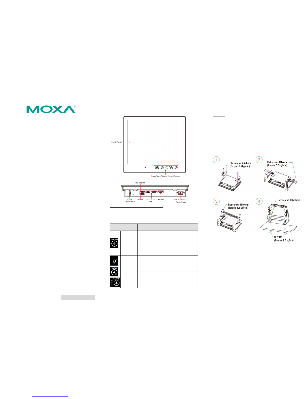
Appearan ce
SavvyT ou ch D isplay Control Bu tt ons
The following table describes the SavvyTouch display controls on
the front surface of the MD-219. These intelligent controls light up
in response to a simple w ave of the hand ov er t he a r ea of t h e
screen where they a re loc ated.
Name
Display
Color
Control Function / Color Legend
Menu/
Power
Green
Display is powered on and
functioni ng nor mal ly. T ouc h the
butto n to show the O S D settings
menu
Red
No input signal detected. Display
standby
Off
Power is down and the display is off
Brightness White
+: To increase brig htness of panel
-: To decr ease brightness of panel
Info
Off AC/DC power func tio ning no r mall y
Red AC/DC power error
Display
mode
White
Swi tch between DAY/DU SK/NIGHT
brigh tn es s mod es
Off
Pane l bri ght ne ss out o f default range
Installing the MD-219
Desktop
The MD-219 comes with optional bra ckets that allow you to insta ll
the display on a horizontal surfac e, such as a desktop. Three round
screws are required for eac h bracke t. See the fig ure at th e top of
the n ext page fo r detailed screw specifications, including the
required tor qu e v al u es.
Plac e your MD-219 display on a clean, flat, well-ventilated desktop.
To pr o te ct the display from overheating, l eave some ventilation
space bet ween the MD-219 and other equipment. Do n o t pl ace
equipment or objec ts on the panel, as thi s mi gh t d a mag e in te rn al
components.
Page 2
– 4 – – 5 – – 6 –
www.moxa.com/support
The Americas:
+1-714-528-6777 (toll-free: 1-888-669-2872)
Europe:
+49-89-3 70 03 99-0
Asia-Pacific:
+886-2-8919-1230
China:
+86-21-5258-9955 (toll-free: 800-820-5036)
2014 Moxa Inc.All rights reserved.
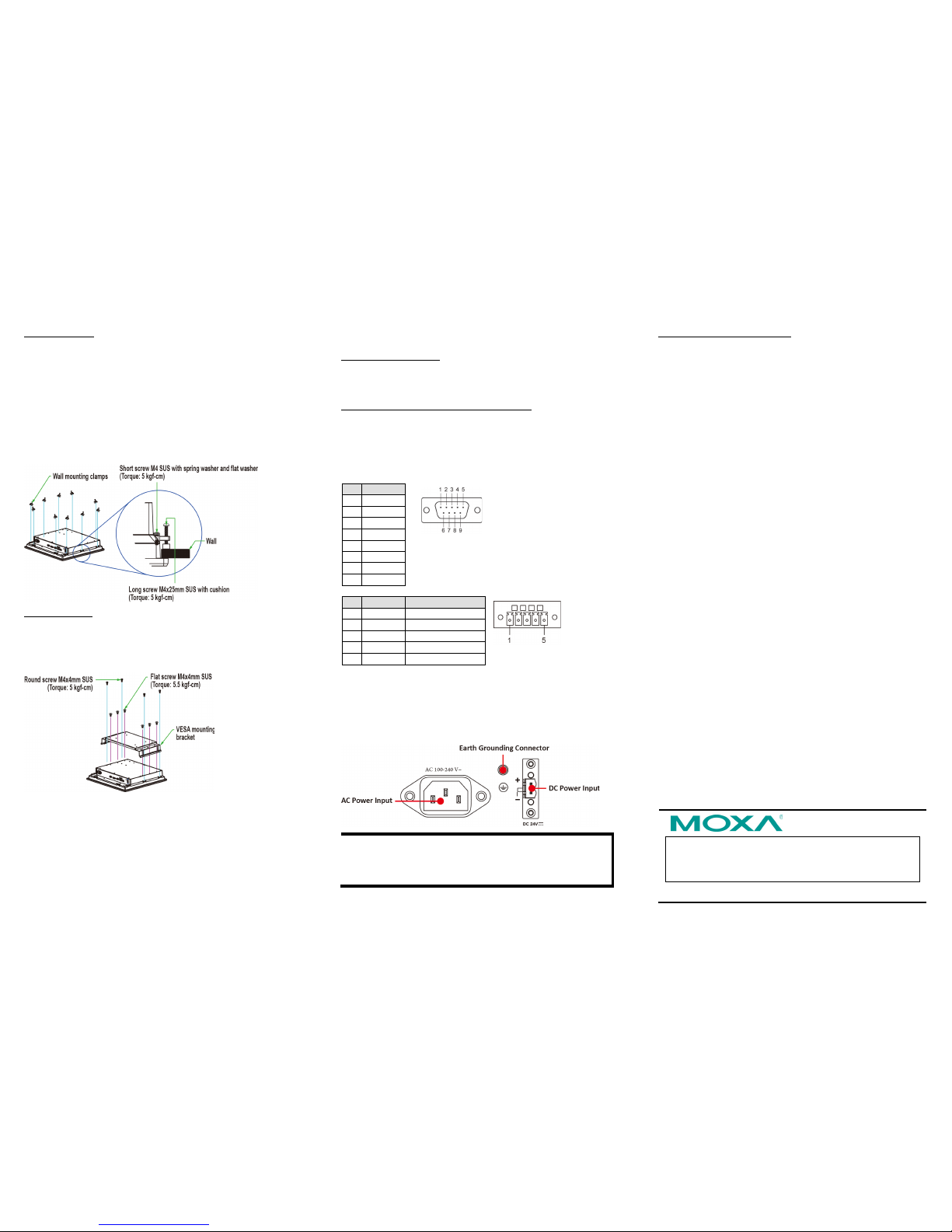
Panel Mounting
The MD-219 com es with 14 optional clamp mounts for installation
on a w all (where space has been cut out to accommodate the rest
of the har dwa re) o r int o com put ing st at io ns whe re a flus h mount is
desired. The max i mum thickness of the surface to which the
display will be clamp ed is 11 mm. For a secure mounting, all 14
clamps must be used. The cl amp arms are fastened int o slot s on all
four sides of t h e MD-219. Use the shor t M 4 SUS screws to fasten
the cl amp a r ms to the MD-219 mounting slots, as s ho wn in the
magnified inset in the d iagram just below. Next, use the c lam p s to
fasten the display to its mountin g point; note the torque value
shown in the figure inset below.
VESA Mounting
The MD-219 also comes with an optional VESA moun ti ng k i t. Six
flat screws and four round screws are required to fasten the VESA
mounting b rac ket . See the f igur e belo w fo r detailed s crew
specifica tions and torq ue valu es.
An addi tional four scr ews (no t in c luded in t he kit) ar e required to
mount the display on a VESA rack. For this purpose, use M6 scre ws
with a length between 10 and 12 mm.
Connector Description
Exten ding the Display
The MD-219 comes wi th both s tandard VGA and DVI-D interfaces
on the bottom pane l . It will au tomatically detect w hether the in put
video source i s fro m the V G A o r DVI-D inter face.
Configuring the Display via the Serial Port
The MD-219 has two s erial ports. The RS-232 p ort us es a DB9
connector, and the RS-422/485 por t uses a termin al block
connector. Either serial port can be used to modify the display
parameters using UART co m m ands. Ref er to the MD-219 User’s
Manual fo r seri al port configuration details. T he pin assig nmen ts
for the ports are shown in the following table:
Pin
RS-232
1
DCD 2 RxD
3
TxD 4 DTR
5
GND
6
DSR 7 RTS
8
CTS
Pin
RS-422
RS-485 (2-wire)
1
RxDB(+)
TDp(+)
2
RxDA(-)
TDn(-) 3 TxDB(+)
RDp(+)
4
TxDA(-)
RDn(-)
5
GND
GND
Powering on/off the MD-219
To powe r o n the MD-219, connect to an AC power source, a DC
power source, or both. Touch the MENU button for 1 second to turn
on the di sp lay. Touc h th e MENU but t on for 4 sec ond s t o tur n off the
display.
NOTE If on ly one p ower inp ut is be in g conn ec ted, the INF O butt o n
will be red. This will not affect the functionality and
performance of MD
-219 as l o ng as the power input i s
stabl e.
Groundin g the M D -219 Series
Proper grounding and wire ro uting help to limit the ef fe ct s o f n oise
from el ectr o ma gnetic interference (EMI). R un the gro u nd
connection from the ground screw to the grounding surface prior to
conn ecting the power source.
For detailed configuration of the MD-219, refer to th e MD-219
Series User’s Manu al.
 Loading...