

Page 1

MC-7400 User’s Manual
Edition 1.0, March 2019
www.moxa.com/product
© 2019 Moxa Inc. All rights reserved.
Page 2

MC-7400 User’s Manual
Moxa Americas
Toll
Tel:
Fax:
Moxa China (Shan
Toll
Tel:
Fax:
Moxa Europe
Tel:
Fax: +49-89-3 70 03 99-99
Moxa Asia
Tel:
Fax: +886-2-8919-1231
Moxa India
Tel:
Fax
The software described in this manual is furnished under a license agreement and may be used only in accordance with
the terms of that agreement.
Copyright Notice
© 2019 Moxa Inc. All rights reserved.
Trademarks
The MOXA logo is a registered trademark of Moxa Inc.
All other trademarks or registered marks in this manual belong to their respective manufacturers.
Disclaimer
Information in this document is subject to change without notice and does not represent a commitment on the part of
Moxa.
Moxa provides this document as is, without warranty of any kind, either expressed or implied, including, but not limited
to, its particular purpose. Moxa reserves the right to make improvements and/or changes to this manual, or to the
products and/or the programs described in this manual, at any time.
Information provided in this manual is intended to be accurate and reliable. However, Moxa assumes no responsibility for
its use, or for any infringements on the rights of third parties that may result from its use.
This product might include unintentional technical or typographical errors. Changes are periodically made to the
information herein to correct such errors, and these changes are incorporated into new editions of the publication.
Technical Support Contact Information
www.moxa.com/support
-free: 1-888-669-2872
+1-714-528-6777
+1-714-528-6778
+49-89-3 70 03 99-0
-free: 800-820-5036
+86-21-5258-9955
+86-21-5258-5505
+886-2-8919-1230
-Pacific
ghai office)
+91-80-4172-9088
: +91-80-4132-1045
Page 3

Table of Contents
1. Introduction ...................................................................................................................................... 1-1
Overview ........................................................................................................................................... 1-2
Package Checklist ............................................................................................................................... 1-2
Product Features ................................................................................................................................ 1-2
Hardware Specifications ...................................................................................................................... 1-3
Hardware Block Diagram .............................................................................................................. 1-3
2. Hardware .......................................................................................................................................... 2-1
Appearance ........................................................................................................................................ 2-2
Dimensions ........................................................................................................................................ 2-4
LED Indicators .................................................................................................................................... 2-5
Real Time Clock .................................................................................................................................. 2-5
3. Hardware Connection Description ..................................................................................................... 3-1
Installing the MC-7400 ........................................................................................................................ 3-2
Wall Mounting ............................................................................................................................. 3-2
Wiring Requirements ........................................................................................................................... 3-3
Connecting the Power ......................................................................................................................... 3-3
Grounding the MC-7400 ...................................................................................................................... 3-4
Connecting Data Transmission Cables ................................................................................................... 3-4
Connecting to the Network ........................................................................................................... 3-4
Connecting to a Serial Device ....................................................................................................... 3-5
Connecting a PS/2 Keyboard and Mouse ................................................................................................ 3-6
Connecting to the USB Device .............................................................................................................. 3-6
Connecting to Digital Input and Output Channels .................................................................................... 3-7
Connecting to a DVI-I/DVI-D Monitor .................................................................................................... 3-8
Connecting to a DisplayPort Monitor ...................................................................................................... 3-9
Installing the Removable SATA Storage Drive ....................................................................................... 3-10
4. BIOS Setup ........................................................................................................................................ 4-1
Entering the BIOS Setup ...................................................................................................................... 4-2
Main Information ................................................................................................................................ 4-4
Advanced Settings .............................................................................................................................. 4-4
Boot Configuration....................................................................................................................... 4-5
SATA Configuration ..................................................................................................................... 4-5
Internal Graphics Device .............................................................................................................. 4-6
Miscellaneous Configuration .......................................................................................................... 4-7
SIO ITE8768E ............................................................................................................................. 4-8
Console Redirection ..................................................................................................................... 4-9
Smart Recovery Info .................................................................................................................. 4-10
Security Settings .............................................................................................................................. 4-10
Set Supervisor Password ............................................................................................................ 4-10
Power Settings ................................................................................................................................. 4-11
Auto Wake on S5 ...................................................................................................................... 4-11
Wake on LAN ............................................................................................................................ 4-12
Boot Settings ................................................................................................................................... 4-12
Boot Type ................................................................................................................................. 4-12
PXE Boot to LAN ........................................................................................................................ 4-12
Add Boot Options ...................................................................................................................... 4-12
Boot Delay Time ........................................................................................................................ 4-13
Automatic Failover ..................................................................................................................... 4-13
Boot Order Priority .................................................................................................................... 4-13
Legacy Normal Boot Menu .......................................................................................................... 4-13
Boot Type Order ........................................................................................................................ 4-13
EFI .......................................................................................................................................... 4-13
Exit Settings .................................................................................................................................... 4-14
Exit Saving Changes .................................................................................................................. 4-14
Save Change Without Exit .......................................................................................................... 4-14
Exit Discarding Changes ............................................................................................................. 4-14
Load Optimal Defaults ................................................................................................................ 4-14
Load Custom Defaults ................................................................................................................ 4-14
Save Custom Defaults ................................................................................................................ 4-14
Discard Changes ....................................................................................................................... 4-14
Upgrading the BIOS .......................................................................................................................... 4-15
A. Regulatory Approval Statement ........................................................................................................ A-1
B. Adjusting the Audio Mixer Function................................................................................................... B-1
Page 4

1
1. Introduction
The chapter describes the product overview, package checklist, product features, and hardware specifications
of the MC-7400 marine computer.
The following topics are covered in this chapter:
Overview
Package Checklist
Product Features
Hardware Specifications
Hardware Block Diagram
Page 5

MC-7400 Series HW UM Introduction
1-2
NOTE
Please notify your sales representative if any of the above items are missing or damaged.
Overview
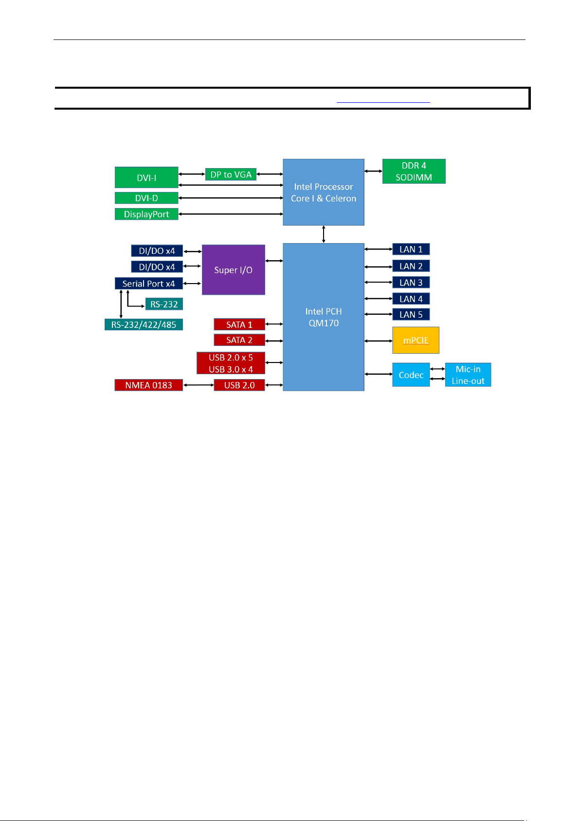
The MC-7400 marine computer is powered by the 6th generation Intel Core™ i processor, delivering a full range
of I/O connectivity, including NMEA 0183 ports, serial ports, Gigabit Ethernet ports, as well as USB 2.0/3.0
ports and a miniPCI slot for extensions. The MC-7400 is designed to provide outstanding PC performance,
bringing a new level of flexibility and control to marine applications.
Package Checklist
Each model ships with the following items:
• 1 MC-7400 computer
• Wall mounting kit, with 8 screws
• 1 3-pin terminal block for DC power input (DC model only)
• 1 2-pin terminal block for power ON/OFF switch
• 4 5-pin terminal blocks for NMEA 0183 ports (MC-7420 model only)
• 1 6-pin digital input terminal block (MC-7420 model only)
• 1 8-pin digital input terminal block (MC-7420 model only)
• Quick installation guide
• Warranty card
Product Features
The MC-7400 embedded computer has the following features:
• 6th Gen. Intel® Core™ i5 processor
• DDR4 SO-DIMM memory up to 32 GB
• 3 independent displays (1 x DVI-I, 1 x DVI-D, 1 x DisplayPort)
• Various I/O interfaces including 9 x USB ports, 5 x LAN ports and 4 x COM ports
• 2 Removable 2.5” SSD storage bay
• AC or DC power model available
• Supports Win 10 IoT and Debian 9 operating systems
• Supports Moxa Proactive Monitoring utility for system status monitoring
Page 6
MC-7400 Series HW UM Introduction
1-3
NOTE
The latest specif
Hardware Specifications
ications for Moxa’s products can be found at https://www.moxa.com.
Hardware Block Diagram
Page 7

2
2. Hardware
The MC-7400 computer is compact, well-designed, and built rugged enough for industrial applications. LED
indicators help you monitor performance and identify trouble spots, multiple serial ports allow you to connect
different devices, and the reliable and stable hardware platform lets you devote your attention to developing
your applications.
The following topics are covered in this chapter:
Appearance
Dimensions
LED Indicators
Real-time Clock
Page 8
MC-7400 Series HW UM Hardware Introduction
2-2
Appearance
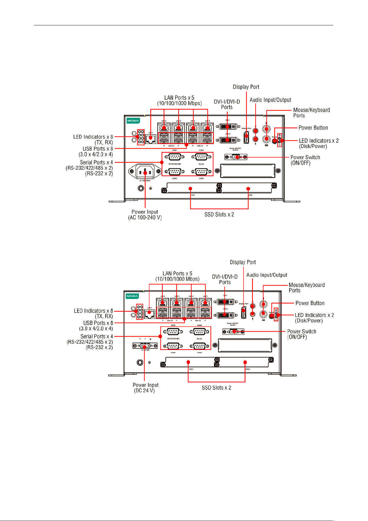
MC-7410 AC Model
MC-7410 DC Model
Page 9
MC-7400 Series HW UM Hardware Introduction
2-3
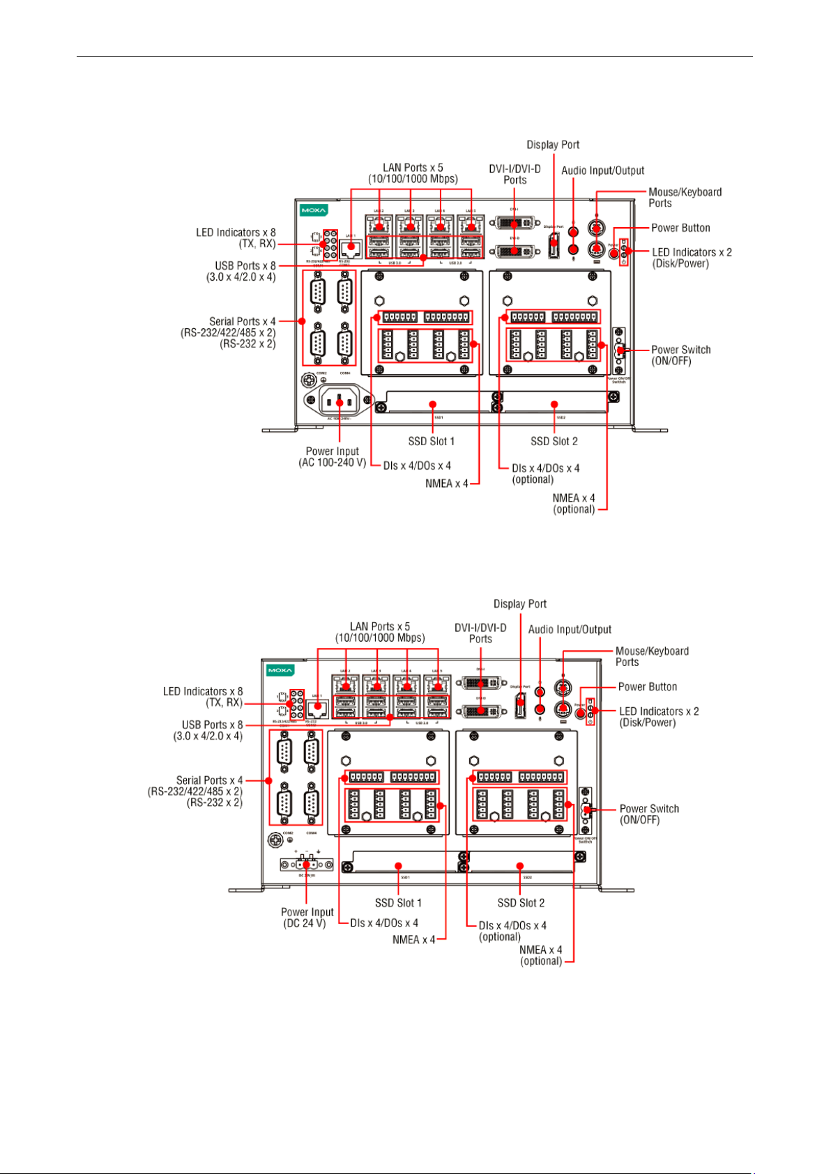
MC-7420 AC Model
MC-7420 DC Model
Page 10
MC-7400 Series HW UM Hardware Introduction
2-4
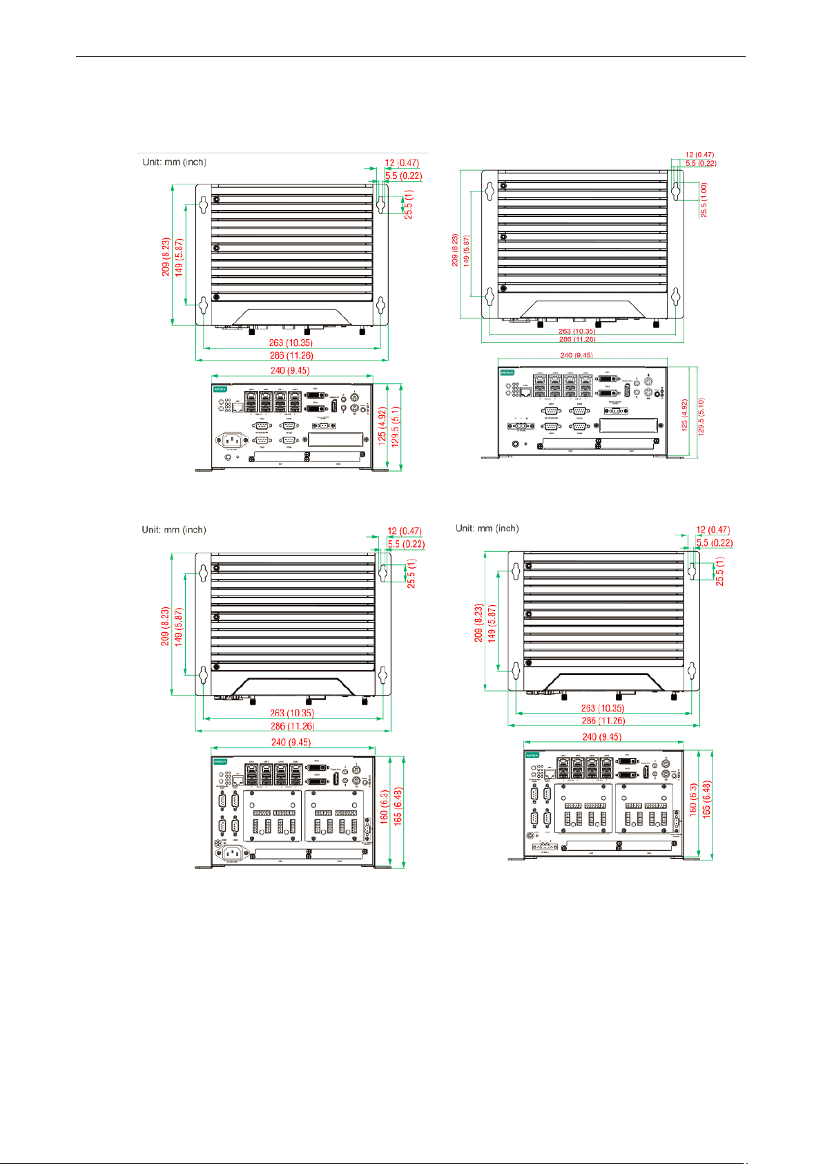
Dimensions
MC-7410 AC Model MC-7410 DC Model
MC-7420 AC Model MC-7420 DC Model
Page 11
MC-7400 Series HW UM Hardware Introduction
2-5
ATTENTION
Used batteries are environmentally hazardous; dispo
WARNING
There is a risk of explosion if the wrong type of battery is used. To avoid this potential danger, be sure to use
the correct type of battery. Contact the Moxa RMA service team if you have any questions about replacing your
battery
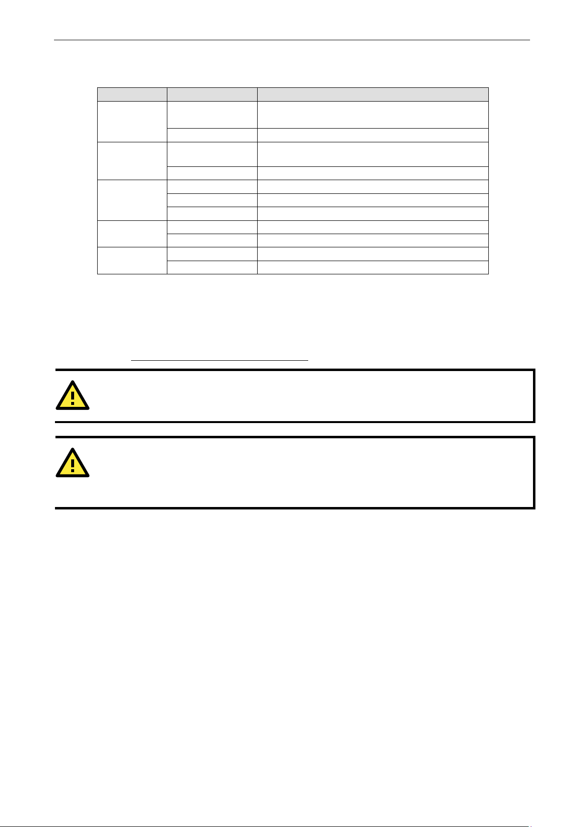
LED Indicators
LED Name LED Color LED Function
Power Green Power is on and the device is functioning normally
Off Power is off or error powering the device
Storage Yellow Blinking: Data transmission
Off No data transmission
LAN (1 to 5) Green 100 Mbps Ethernet mode
Yellow 1000 Mbps (Gigabit) Ethernet mode
Off No activity or 10 Mbps Ethernet mode
Tx 1/2/3//4 Green Blinking: Data is being transmitted
Off No data transmission
Rx 1/2/3//4 Yellow Blinking: Data is being received
Off No data
Real-time Clock
The embedded computer’s real-time clock is powered by a lithium battery. We strongly recommend that you do
NOT replace the lithium battery yourself. If the battery needs to be changed, contact the Moxa RMA service
team at http://www.moxa.com/rma/about_rma.aspx
.
.
se of them in the proper manner.
Page 12

3
3. Hardware Connection Description
In this chapter, we show how to connect the embedded computers to the network and to various devices.
The following topics are covered in this chapter:
Installing the MC-7400
Wall Mounting
Wiring Requirements
Connecting the Power
Grounding the MC-7400
Connecting Data Transmission Cables
Connecting to the Network
Connecting to a Serial Device
Connecting a PS/2 Keyboard and Mouse
Connecting to the USB Device
Connecting to Digital Input and Output Channels
Connecting to a DVI-I/DVI-D Monitor
Connecting to a DisplayPort Monitor
Installing the Removable SATA Storage Drive
Page 13
MC-7400 Series HW UM Hardware Connection Description
3-2
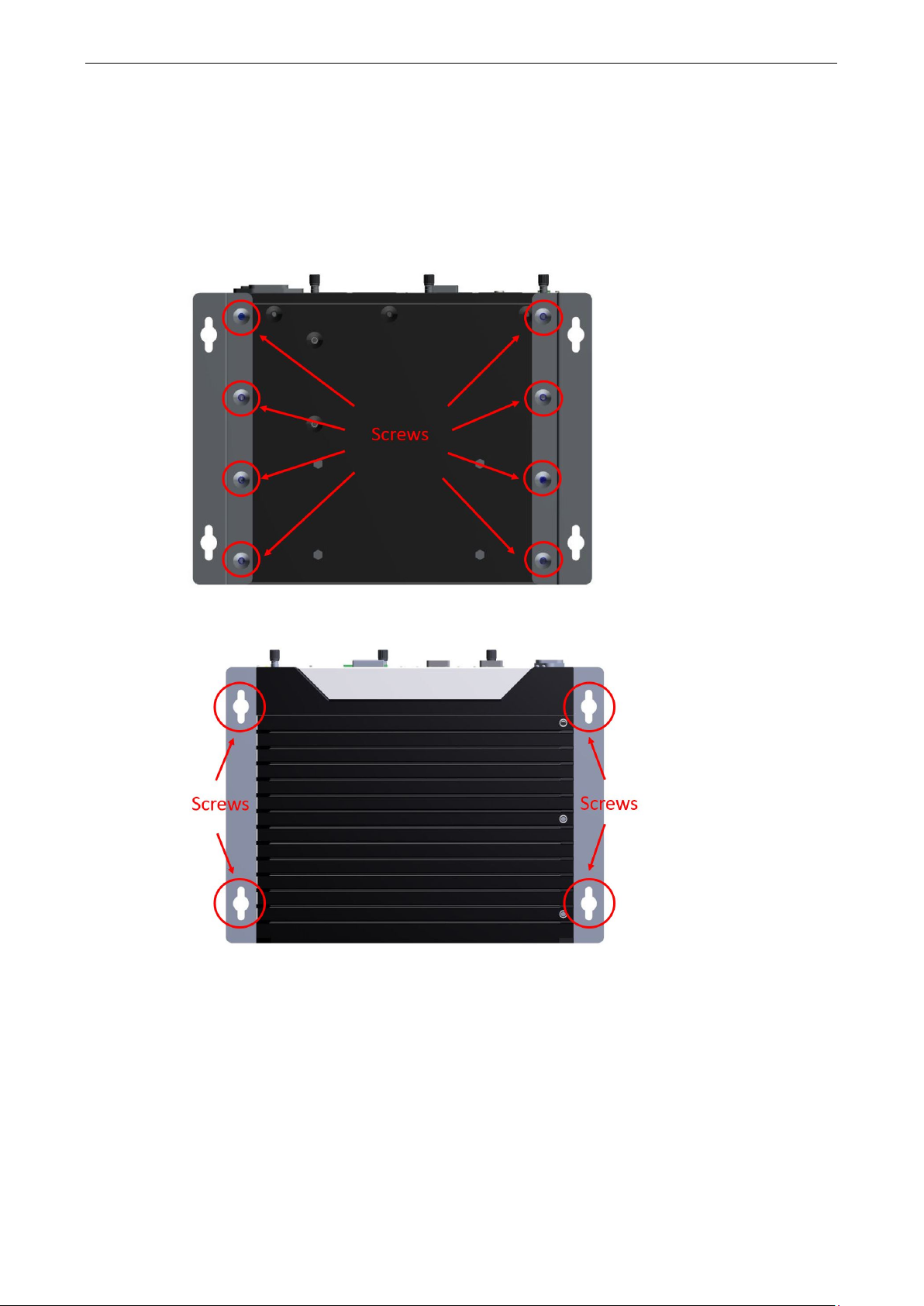
Installing the MC-7400
Wall Mounting
The MC-7400 can be installed on a wall by using the wall-mounting kit that is included in the package.
STEP 1: Use eight screws for each bracket and attach the brackets to the rear of the MC-7400.
STEP 2: Use two screws (Ø3.7 mm, 60 mm in length) per side to attach the MC-7400 to a wall.
Page 14

MC-7400 Series HW UM Hardware Connection Description
3-3
NOTE
Do not run signal or communication wiring together with power wiring in the same wire conduit. To avoid
interference, wires with different signal characteristics should be routed separately.
ATTENTION
Safety First!
Be sure to disconnect the power cord before installing and/or wiring your
Wiring Caution!
Calculate the maximum possible current in each power wire and common wire. Observe a
dictating the maximum current allowable for each wire size. If the current goes above the maximum ratings,
the wiring could overheat, causing serious damage to your equipment.
Temperature Caution!
Be careful when handling
internal components generate heat, and
consequently the outer casing may feel hot to the touch.
NOTE
The DC model should be supplied by
listed power source, whose output meets the ES1 standard and is
rated at 24 VDC, 4.06 A (min.)
representative
Wiring Requirements
Read and follow these common safety precautions before proceeding with the installation of any electronic
device:
• Use separate paths to route wiring for power and devices. If power wiring and device wiring paths must
cross, make sure the wires are perpendicular at the intersection point.
• Use the type of signal transmitted through a wire to determine which wires should be kept separate. The
rule of thumb is that wiring that shares similar electrical characteristics can be bundled together.
• Keep input wiring and output wiring separate.
• It is advisable to label the wiring on all devices in the system.
the unit. When the unit is plugged in, the
Connecting the Power
The MC-7400 Series comes with a 100 to 240 VAC power input for AC power model, or a 24 VDC power input
(via the terminal block) for DC power model. If power is supplied properly, the Power LED will light up.
For safety reasons, please use DC terminal block cables with the following specifications:
Wire range: 14-22 AWG
MC-7400.
ll electrical codes
.
a UL-
. If you need further assistance selecting a power source, contact a Moxa
Page 15

MC-7400 Series HW UM Hardware Connection Description
3-4
ATTENTION
This product is intended to be mounted
The LED indicator
(for the
lower LAN connector) corners glow a solid green color when the cable is properly connected
to a 100 Mbps Ethernet network. The LED will flash on and off when Ethernet packets are
being transmitted or received.
The LED indicator
color when
the cable is properly connected to a 10
Mbps Ethernet network. The LED will flash on and
off when Ether
Grounding the MC-7400
Grounding and careful wire routing help limit the effects of noise due to electromagnetic interference (EMI).
Run the ground connection from the ground screw to the grounding surface prior to connecting the power.
The location of the earthing/grounding wire on the terminal block power connector is shown in the diagram
below. Connect the wire to an appropriately grounded metal surface.
on a well-grounded surface, such as a metal panel.
Connecting Data Transmission Cables
This section describes how to connect the MC-7400 computer to the network and/or serial devices.
Connecting to the Network
Plug your network cable into the computer’s Ethernet port. The other end of the cable should be plugged into
your Ethernet networking device. When the cable is properly connected, the LEDs on the embedded computer’s
Ethernet port will glow to indicate a valid connection.
The 10/100/1000 Mbps Ethernet LAN ports use 8-pin RJ45 connectors. The following diagram shows the
pinouts for these ports.
s on the right-top (for the upper LAN connector) and right-bottom
s on the left-top and left-bottom corners glow a solid yellow
Pin 10/100 Mbps 1000 Mbps
1 ETx+ TRD(0)+
2 ETx- TRD(0)-
3 ERx+ TRD(1)+
4 – TRD(2)+
5 – TRD(2)-
6 ERx- TRD(1)-
7 – TRD(3)+
8 – TRD(3)-
net packets are being transmitted or received.
00
Page 16

MC-7400 Series HW UM Hardware Connection Description
3-5
DB9 Male
RS
Connecting to a Serial Device
The serial ports use DB9 connectors. COM1 and COM2 support RS-232. COM3 and COM4 support RS-232,
RS-422, or RS-485. The AP from the CD can be used to configure both COM1 and COM2. For detailed
instructions, please refer to Appendix C. The pin assignments are shown in the following table:
Port
Additionally, there are four NMEA 0183 ports with terminal blocks on the front panel of the computer. Refer to
the following figures for the location of the NMEA ports and the pin assignments.
-232/422/485 Pinouts
Pin RS-232 RS-422 RS-485 (4-wire) RS-485 (2-wire)
1 DCD TxDA(-) TxDA(-) –
2 RxD TxDB(+) TxDB(+) –
3 TxD RxDB(+) RxDB(+) DataB(+)
4 DTR RxDA(-) RxDA(-) DataA(-)
5 GND GND GND GND
6 DSR – – –
7 RTS – – –
8 CTS – – –
Page 17

MC-7400 Series HW UM Hardware Connection Description
3-6
PS/2 Connector
Connecting a PS/2 Keyboard and Mouse
Your MC-7400 computer comes with 2 PS/2 mini-DIN connectors on the rear panel to connect to a PS/2
keyboard and PS/2 mouse.
This 6-pin mini-DIN connector has the pin assignments shown below.
Pin No. Signal Definition
1 PS/2 Keyboard Data
2 PS/2 Mouse Data
3 GND
4 VCC
5 PS/2 Keyboard Clock
6 PS/2 Mouse Clock
Connecting to the USB Device
The MC-7400 comes with two USB 2.0 hosts on the front panel, four USB 2.0 hosts, and two SuperSpeed USB
3.0 hosts on the rear panel. The USB ports support peripherals such as a keyboard or mouse, or storage
devices such as a portable HDD or DVD-ROM. Please note that USB 3.0 interfaces are not supported by the
Windows XP platform.
Page 18

MC-7400 Series HW UM Hardware Connection Description
3-7
Connecting to Digital Input and Output Channels
The MC-7400 comes with four digital input and four digital output channels on the front panel. These
input/output channels can be connected with the terminal blocks that have been included in the package.
Page 19

MC-7400 Series HW UM Hardware Connection Description
3-8
Pin No.
7
DDC Data
13
(return for +5V, HSync, and VSync)
21
N/C
C1
C2
C3
C4
C5
Connecting to a DVI-I/DVI-D Monitor
The MC-7400 computer come with one DVI-I and one DVI-D connectors that can connect to DVI monitors. Use
the cable to connect one end to the DVI-I connector and the other end to the monitor. See the following table
for DVI-I/DVI-D connector pin assignments.
1
2
3
4
5
6
Signal Definition
T.M.D.S. Data2-
T.M.D.S. Data2+
T.M.D.S. Data2/4 Shield
N/C
N/C
DDC Clock
8
9
10
11
12
14
15
16
17
18
19
20
22
23
24
Analog Vertical Sync
T.M.D.S. Data1-
T.M.D.S. Data1+
T.M.D.S. Data1/3 Shield
N/C
N/C
+5V Power
Ground
Hot Plug Detect
T.M.D.S. Data0-
T.M.D.S. Data0+
T.M.D.S. Data0/5 Shield
N/C
T.M.D.S. Clock Shield
T.M.D.S. Clock+
T.M.D.S. Clock-
Analog Red
Analog Green
Analog Blue
Analog horiz. Sync
Analog GND
Page 20

MC-7400 Series HW UM Hardware Connection Description
3-9
Pin No.
15
AUX CH (p)
Connecting to a DisplayPort Monitor
The MC-7400 computer come with one DisplayPort connector to connect to monitor which support 4K
resolution.
1
2 GND
3 ML_Lane 0 (n)
4
5 GND
6 ML_Lane 1 (n)
7
8 GND
9 ML_Lane 2 (n)
10
11
12
13
14
Signal Definition
ML_Lane 0 (p)
ML_Lane 1 (p)
ML_Lane 2 (p)
ML_Lane 3 (p)
GND
ML_Lane 3 (n)
CONFIG1
CONFIG2
16
17
18
19
20
GND
AUX CH (n)
Hot Plug
Return
DP_PWR
Page 21

MC-7400 Series HW UM Hardware Connection Description
3-10
Installing the Removable SATA Storage Drive
The MC-7400 computer comes with two removable SATA storage tray that is accessible through the front panel.
Either a SATA hard disk or solid state drive may be installed, but only use of an SSD will ensure full
anti-vibration compliance. To install a SATA storage device, please follow these instructions:
1. Disconnect the MC-7400 from the power source.
2. To remove the storage device tray, unfasten the two thumbscrews that secure the removable tray.
The storage tray’s location is indicated in the following diagram:
3. Pull out the removable tray and fasten the storage device, such as HDD or SSD, on the tray.
4. When finished, insert back the storage tray into place.
Page 22

4
4. BIOS Setup
This chapter describes the BIOS settings of the MC-7400 computer. The BIOS is a set of input/output control
routines for peripherals. The BIOS is used to initialize basic peripherals and helps boot the operating system
before the operating system is loaded. The BIOS setup allows the user to modify the system configurations of
these basic input/output peripherals.
The following topics are covered in this chapter:
Entering the BIOS Setup
Main Information
Advanced Settings
Boot Configuration
SATA Configuration
Internal Graphics Device
Miscellaneous Configuration
SIO ITE8768E
Smart Recovery Info
Security Settings
Set Supervisor Password
Power Settings
Auto Wake on S5
Wake on LAN
Boot Settings
Boot Type
PXE Boot to LAN
Add Boot Options
Boot Delay Time
Legacy Normal Boot Menu
Boot Type Order
Exit Settings
Exit Saving Changes
Save Change Without Exit
Exit Discarding Changes
Load Optimal Defaults
Load Custom Defaults
Save Custom Defaults
Discard Changes
Upgrading the BIOS
Page 23

MC-7400 Series HW UM BIOS Setup
4-2
Entering the BIOS Setup
To enter the BIOS setup utility, press the “F2” key while the system is booting up. The main BIOS Setup
screen is displayed. The following four options are available:
Continue: Continue to boot up
Boot Manager: Select the device for booting up
Boot From File: Select the UEFI boot-up file
SCU: Enter the BIOS configuration
Select SCU to enter the BIOS configuration.
Page 24

MC-7400 Series HW UM BIOS Setup
4-3
F1
F5/
F9
F10
General Help
Change Values
Setup Defaults
Save and Exi
↑↓
←→
ESC
EN
Select Item
Select Menu
Exit
Select or go to Submenu.
NOTE
have
purchase
The following BIOS configuration screen will be shown when you enter SCU option:
When you enter SCU, a basic description of each function key is listed at the bottom of the screen. Refer to
these descriptions to learn how to use them.
F6
The information displayed for a Processor Type may vary depending on the computer model that you
d.
t
.
TER
Page 25

MC-7400 Series HW UM BIOS Setup
4-4
Main Information
The Main page indicates the system information, such as model name, BIOS version, and CPU type. You can
view the basic system hardware information on this page.
Advanced Settings
The Advanced option displays configuration information on Boot, SATA, internal graphics device, SIO, and
Smart Recovery feature.
Page 26

MC-7400 Series HW UM BIOS Setup
4-5
Boot Configuration
This feature allows you to configure a default setting for the keys on the number pad of the computer keyboard.
Turning the NumLock on allows you to use the number keys to type out numbers and turning it off activates
the key's other functions such as using the keypad as an arrow pad.
Option: On (default), Off.
SATA Configuration
The host drive controller can be configured for AHCI or RAID mode.
When the AHCI mode is selected, the following screen is displayed:
Page 27

MC-7400 Series HW UM BIOS Setup
4-6
SATA Port 0 to 2 Hot Plug
This feature allows you to enable/disable hot plugging capabilities (the ability to remove the drive while the
computer is running) for the storage drives installed on the system.
Options: Disable (default), Enabled
Internal Graphics Device
Allows you to enable/disable the internal graphics device.
IGD—DVMT (pre-allocated)
Allows you to configure pre-allocated memory capacity for the IGD. Pre-allocated graphics memory is invisible
to the operating system.
Options: 64 MB (default), 32 MB, 96 MB, 128 MB, 256 MB, 512 MB
DVMT is a BIOS solution where the optimum amount of memory is dynamically allocated and de-allocated as
needed for balanced graphics and system performance, through Intel® Direct AGP and a highly efficient
memory utilization scheme. DVMT ensures the most efficient use of available system memory resources for
maximum 2D/3D graphics performance.
IGD—DVMT Size
Allows you to configure the maximum amount of memory DVMT will use when allocating additional memory for
the internal graphics device.
Options: 256 MB (default), 128 MB, Max
Page 28

MC-7400 Series HW UM BIOS Setup
4-7
Miscellaneous Configuration
Power ON after Power Failure
Allows you to enable/disable the automatic power up of your computer after a system crash.
Options: ON (default), OFF, Last State
Page 29

MC-7400 Series HW UM BIOS Setup
4-8
SIO ITE8768E
Serial Port A
Allows you to configure the serial port A.
Options:
Auto (Default) The system chooses the configure for the resource
Enable User configures the resource
Disable Port is disabled and no configuration is possible
Serial Port B
Allows you to configure the serial port B.
Options:
Auto (Default) The system chooses the configure for the resource
Enable User configures the resource
Disable Port is disabled and no configuration is possible
Page 30

MC-7400 Series HW UM BIOS Setup
4-9
Hardware Monitor
This feature allows you to view hardware statistics like CPU and system temperature, voltage levels, and other
chipset related information.
Console Redirection
Console Serial Redirect
Enables console redirection function. The display will also output to serial port synchronously.
Page 31

MC-7400 Series HW UM BIOS Setup
4-10
Smart Recovery Info
This feature allows you to view the smart recovery settings for your computer.
Load Smart Recovery Default
Allows you to load the default values for the Smart Recovery function. For details on the Smart Recovery
feature, refer to the Smart Recover Software User’s Manual.
Options: Yes (default), No
Security Settings
This feature allows you to configure security settings with a supervisor password and user password.
Set Supervisor Password
Allows you set the supervisor password.
To set the password, enter the password, and then confirm the password again.
To delete the password, enter Set Supervisor Password and enter the old password. Leave the new
password fields blank, and press Enter.
Page 32

MC-7400 Series HW UM BIOS Setup
4-11
Power Settings
The Power menu allows you to configure the power settings for your computer.
The Advanced CPU Control option is only available on i7 platform. The C-States option is disabled by default.
Auto Wake on S5
This feature allows you to configure auto wake up from S5 status. S5 stands for Soft Off, where the PSU
remains engaged but power to all other parts of the system is cut off. Auto-wake on S5 schedules a soft-reboot
at certain periodic times that can be specified in the BIOS.
Options: Disabled (default); By Every Day (user specifies a regular daily time when the computer will power
up); By Day of Month (user specifies a regular day each month when the computer will power up)
Page 33

MC-7400 Series HW UM BIOS Setup
4-12
Wake on LAN
This feature is used to configure a wake on the system by a LAN device from a remote host.
Options: Enabled (default), Disable.
Boot Settings
The feature allows you to configure boot settings.
Boot Type
Allows you to enable/disable quick boot function.
Options: Dual Boot Type (default), Legacy Boot Type, UEFI Boot Type.
PXE Boot to LAN
Allows you to enable/disable PXE boot to LAN function.
Options: Disabled (default), Enabled
Add Boot Options
Allows you to add the boot order options for shell, network, and removable media.
Options: Last (default), First
Page 34

MC-7400 Series HW UM BIOS Setup
4-13
Boot Delay Time
Allows you to configure the delay time value for users to input hot key during POST time.
Options: 0 Second (default), 3 Seconds, 5 Seconds, and 10 Seconds
Automatic Failover
This setting allows you to enable automatic failover to the next boot device if the default device fails to boot.
Enable: If the default device fails to boot, the system will automatically try to boot up the next device.
Disable: If the default device fails to boot, the system will display a warning message and the go into
firmware.
Boot Order Priority
This setting allows you to determine the booting priority of the EFI device. If this setting is set to EFI First, the
EFI device will boot first; if the setting is Legacy First, the legacy device will boot first.
Options: Legacy First (default), EFI first
Legacy Normal Boot Menu
This setting allows you to configure the boot menu.
Options: Normal, Advance (default)
Boot Type Order
This setting allows you to configure the boot order of the devices. To change the boot order, use the “-” or “F5”
key to move down the list, or the “+” or “F6” key to move up the list, and then press Enter.
Options: Hard Disk Drive (default), CD/DVD-ROM Drive, USB, Others
EFI
Adjust boot order settings for EFI device
Page 35

MC-7400 Series HW UM BIOS Setup
4-14
Exit Settings
The feature allows users to save configuration changes and exit the BIOS environment.
Exit Saving Changes
Allows you to exit the BIOS environment and save the values you have just configured.
Options: Yes (default), No
Save Change Without Exit
Allows you to save changes without exiting the BIOS environment.
Options: Yes (default), No
Exit Discarding Changes
Allows you to exit without saving any changes that might have been made to the BIOS.
Options: Yes (default), No
Load Optimal Defaults
Allows you to revert to the factory default BIOS values.
Options: Yes (default), No
Load Custom Defaults
Allows you to load custom default values for the BIOS settings.
Options: Yes (default), No
Save Custom Defaults
Allows you to save the current BIOS values as a custom default image. You can restore the system to this
custom default image anytime using the Load Custom Defaults option.
Options: Yes (default), No
Discard Changes
Allows you to discard all settings you have just configured. Options: Yes (default), No
Page 36

MC-7400 Series HW UM BIOS Setup
4-15
IMPORTANT
BIOS upgrades, if not done correctly, can permanently damage the computer. We strongly recommend that
you contact Moxa’s technical support staff for assistance in order to obtain all necessary tools and the most
current advice before attempting to upgrade the BIOS on any Moxa device.
1.
to
.
2.
3.
4.
5.
6.
7.
ATTENTION
We suggest you use a USB drive with under 2 GB disk space, as larger USB drives may not support FAT file
format and consequently fail to boot.
Upgrading the BIOS
This section describes how to upgrade the BIOS.
Step 1: Create a Bootable USB Disk
Before upgrading the BIOS, you must create a bootable USB RAM drive, which you can use as a system rescue
device. A useful software suite, Rufus for creating a bootable USB RAM drives can be downloaded at:
https://rufus.akeo.ie/
To create a bootable USB disk using Rufus software, do the following:
Start Rufus and select the USB device that you want
use as a bootable disk from the Device drop-down list
Select MBR partition scheme for BIOS or UEFI
computers to boot from a legacy BIOS or UEFI.
Select FAT (Default) from File system drop-down
list.
Select 16 kilobytes (Default) for Cluster size.
Enter a drive name under New volume label.
Select the Quick format, Create a bootable disk
using FreeDOS, and Create extended label and
icon files format options.
Click Start to format and create the bootable USB
drive.
Step 2: Prepare the Upgrade File
You must use the BIOS upgrade installation file to upgrade the BIOS. Contact Moxa’s technical department for
assistance.
1. Get the BIOS upgrade installation file. The file name should have following format: 682AxxSx.exe (xx
refers to version numbers).
2. Copy the file to the Bootable USB Disk.
Page 37

MC-7400 Series HW UM BIOS Setup
4-16
C:
C:
Step 3: Run the upgrade program on the MC-7400 Computer
1. Reboot the computer, press F12 while booting up to enter the Boot Manager
2. Select USB Disk as the first boot source. Press Enter to continue.
3. When the boot up process is complete, the DOS screen is displayed. Go to the directory where the upgrade
file is located. For example, if the upgrade file is stored in the DA-720 folder, type
cd DA-720.
\cd DA-720
4. Run the upgrade program by typing DA-72010017.exe. Please note that the upgrade filename will vary
depending on the computer versions.
\ DA-720>DA-72010017.exe
5. Wait until the upgrade process is complete.
Page 38

MC-7400 Series HW UM BIOS Setup
4-17
ATTENTION
DO NOT switch off the power supply during the BIOS upgrade, since doing so may cause the system to crash.
6. When the upgrade is finished, the computer will automatically reboot. You can check the BIOS version on
Main page of the BIOS Setup to confirm the upgrade.
Page 39

A
This device complies with part 15 of the FCC Rules. Operation is subject to the following
two conditions: (1) This device may not cause harmful interference, and (2) this device
must accept any interference received, including interference that may cause undesired
operation.
European Community
A. Regulatory Approval Statement
Class A: FCC Warning! This equipment has been tested and found to comply with the limits for a Class A digital
device, pursuant to part 15 of the FCC Rules. These limits are designed to provide reasonable protection
against harmful interference when the equipment is operated in a commercial environment. This equipment
generates, uses, and can radiate radio frequency energy and, if not installed and used in accordance with the
instruction manual, may cause harmful interference to radio communications. Operation of this equipment in
a residential area is likely to cause harmful interference in which case the user will be required to correct the
interference at his own expense.
Warning:
This is a class A product. In a domestic environment this product may cause radio interference in which case
the user may be required to take adequate measures.
Page 40

B
B. Adjusting the Audio Mixer Function
This chapter describes how to adjust the of the MC-7400’s audio settings for the Mixer function in the Windows
XP and Windows XP Embedded operating systems.
Since the Mixer function is enabled by default, you need modify the default settings of the Realtek audio device
so that sounds picked up from the microphone will not be recorded. Follow the steps below:
1. Right-click the volume icon and select Open Volume Control.
2. Select Properties.
3. Select Realtek HD Audio Input from the Mixer device drop-down list, and check Stereo Mix. Click OK to
continue.
Page 41

MC-7400 Series HW UM Adjusting the Audio Mixer Function
C-2
4. Uncheck Stereo Mix and choose Mix Volume to complete the configuration.
 Loading...