

Page 1
– 1 – – 2 – – 3 –
P/N: 1802072700010
MC-7270-DC-CP-T Series
Quick Installation Guide
First Edition, July 2015
Overview
The MC-7270-DC-CP-T computer uses the Intel® Core™ CPU processor
and comes with 4 ser ial ports, 4 Gigabit Ethernet ports, and 6 USB
hosts. The computer offers high performance and versatile
peripherals for industrial app lications.
Package Checklist
Before installin g the MC-7270-DC-CP-T, verify that the package
contains the fo llowing items:
• 1 MC-7270-DC-CP-T embedded computer
• 1 2-pin termin al block for DC power input
• 1 2-pin terminal block for power ON/OFF switch
• Hard disk installa tion kit
• Documentation and driver CD
• Quick installation guide (printed)
• Warranty card
NOTE: Please notify your sales representative if any of the
above items are missing or damaged.
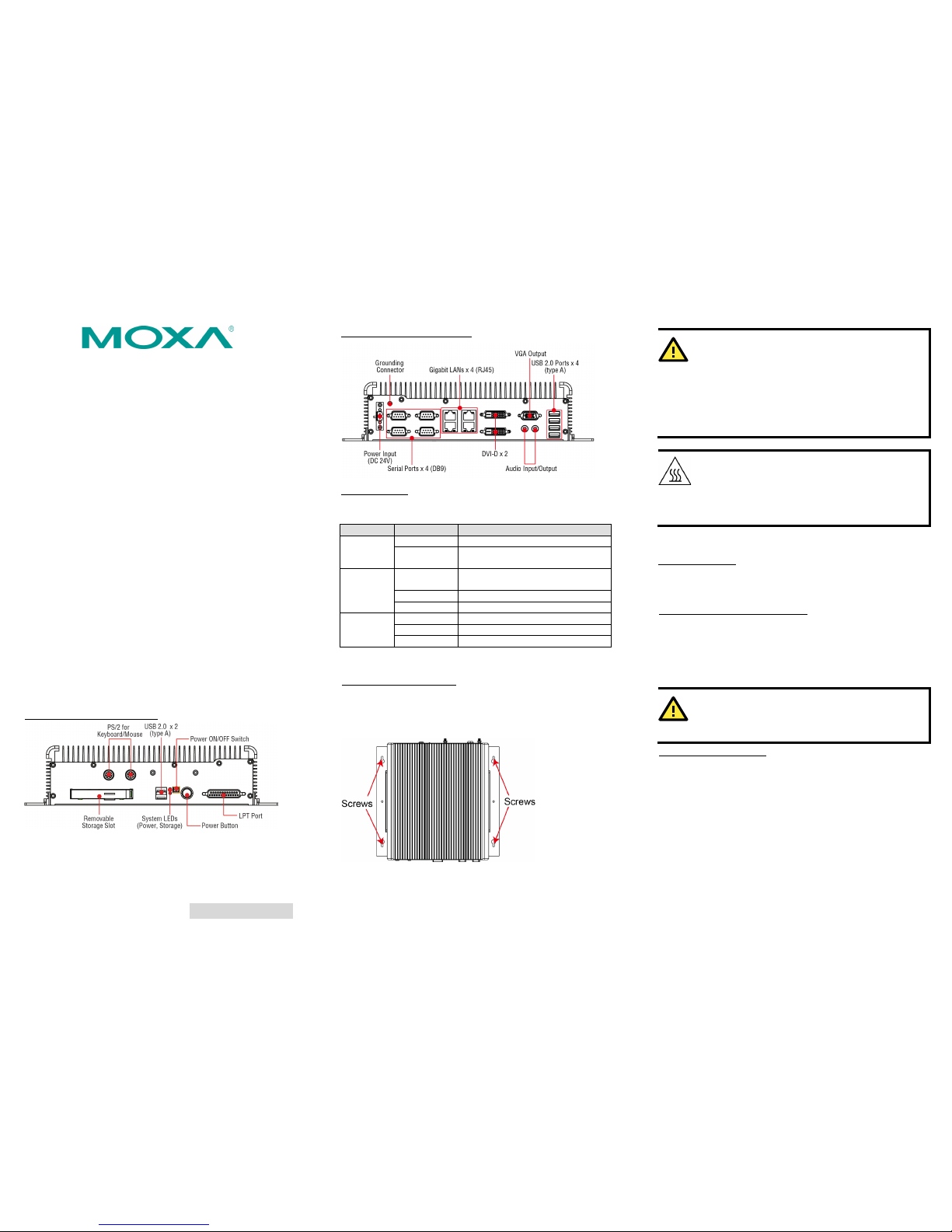
MC-7270-DC-CP-T Panel Layout
The following figu res show the pane l layouts of the
MC-7270-DC-CP-T.
MC-7270-DC-CP-T Front View
MC-7270-DC-CP-T Rear V iew
LED Indicators
The following t able describe s the LED indicat ors located on th e
front panel and th e LAN ports of the MC-7270-DC-CP -T.
LED Name
LED Color
LED Function
Power ( on
the front
panel)
Green
Power is on and functioning normally
Off Power is off or power error exists
Storage (on
the front
panel)
Red (on) HDD/SSD card is inserted and
detected
Red (blinkin g)
HDD/SSD card is re ading/writin g
Off
No activity
LAN (on
each LAN
port)
Green
100 Mbps Ethernet mode
Yellow
1000 Mbps (Gigabit) Ethernet mode
Off
No activity or 10 Mbps Ethernet mode
Installing the MC-7270-DC-CP-T
Wall or Cabinet Mounting
The MC-7270-DC-CP-T comes with two brackets pre-installe d on
both ends of the computer. Use two screws per side to attach the
MC-7270-DC-CP-T to a wall or cabinet. We recommend using size
M4 or larger screws.
Restricted Access Location
T
his equipment is intended t
o be used in restricted access
locations, such as a computer room, with access limit
ed
to
service person
nel or users who have been instructed on
how to handle the metal chassis of equipment that is so hot
that special protection may be needed before touchi
ng it.
The location should only be accessible with a key or
through a security identity system.
W
ARNING
External metal parts of this equipment are extremely hot!
Before touching the equipment, you must take special
precautions to protect your hands
and body from serious
injury.
Connector Description
Power Connector
The MC-7270-DC-CP-T model h as a 24 VDC power in put (via the
terminal block). If power is supplied properly, the Power LED will
light up. The OS is ready when the Ready LED is a steady green.
Grounding the MC-7270-DC-CP-T
Proper grounding and wire routing help limit the effects of noise
from electromagnetic interference (EMI). Run the ground
connection from the ground screw to the grounding surface prior to
connecting the power. There is a ground symbol next to the
connector. Connect the ground wire to an appropriate grounded
metal surface.
ATTENTION
This product is intended to be mounted
on a well-
grounded
mounting surface, such as a metal panel.
VGA and DVI-D Outputs
The MC-7270-DC-CP-T comes with a DB-15 female connector on
the rear panel to connect a VGA monitor, and has two DVI-D
connector s on the rear panel to connect displays over a Digital
Visual Interface.
Page 2

– 4 – – 5 – – 6 –
www.moxa.com/support
The Americas:
+1-714-528-6777 (toll-free: 1-888-669-2872)
Europe:
+49-89-3 70 03 99-0
Asia-Pacific:
+886-2-8919-1230
China:
+86-21-5258-9955 (toll-free: 800-820-5036)
2015 Moxa Inc. All r ights reserved.
Ethernet Ports
The 10/100/1000 Mbps Ethernet ports use RJ45 connectors.
Pin
10/100 Mbps
1000 Mbps
1
ETx+
TRD(0)+
2
ETx-
TRD(0)-
3
ERx+
TRD(1)+
4 – TRD(2)+
5 – TRD(2)-
6
ERx-
TRD(1)-
7 – TRD(3)+
8 – TRD(3)-
Serial Ports
The serial ports use DB9 connectors. COM1 and COM2 support
RS-232, and COM3 and COM4 support RS-232, RS-422, and
RS-485.
Pin
RS-232
RS-422
RS-485
(4-wire)
RS-485
(2-wire)
1
DCD
TxDA(-)
TxDA(-)
–
2
RxD
TxDB(+)
TxDB(+)
–
3
TxD
RxDB(+)
RxDB(+)
DataB(+)
4
DTR
RxDA(-)
RxDA(-)
DataA(-)
5
GND
GND
GND
GND
6
DSR – –
–
7
RTS – –
–
8
CTS – –
–
Removable Storage Trays
The MC-7270-DC-CP-T computer has a removable storage de vice
tray on the front panel. You may inst all an SSD storage drive for
storage expansion. In addition, an inter nal SATA expans ion slot for
additional driv es is also availa ble on the bottom of the computer.
You may install either a hard disk drive or an SSD in the storage
expansion slot; however, for high-vibration environments, Moxa
recommends using an SSD for greater system stability. To
increase system safety, use a hex-type screwdriver to lock the
front panel’s removable tray in place.
Power ON/OFF Swi tch
The Power ON/OFF switch functions like the Power button on the
front panel of the MC-7270-DC-CP-T. The Power ON/OFF switch
enables you to turn the MC-7270-DC-CP-T on or off remotely from
a cabinet control desk.
To use the Power ON/OFF switch, connect a 2-pin termina l block to
the switch. We recommend that you use a tactile switch instead of
a push button switch.
USB Hosts
The MC-7270-DC-CP-T has six USB 2.0 full speed hosts that use a
type A connector. The port supports keyboard and mouse, and can
also be used to connect a FlashDisk for storing large amounts of
data.
Audio Interface
The MC-7270-DC-CP-T comes with an audio input and an audio
output, allowing users to connect a speaker or an earphone.
Real-time Clock
The MC-7270-DC-CP-T’s real-tim e clock is power ed by a lithium
battery. We strongly recommend that you do not replace the
lithium battery without help from a qualified Moxa support
engineer. If you need to change the battery, contact the Moxa RMA
service team at http://www.moxa.com/rma/about_rma.aspx
.
ATTENTION
There is a risk o f explosion if the battery is replaced wit h an
unapproved type of battery.
Powering on the MC-7270-DC-CP-T
To turn on the MC-7270-DC-CP-T, connect a 24 VDC power source
to the DC terminal block on the MC-7270-DC-CP-T. After you
connect the power source, the computer automatically starts. You
do not need to press the Power button.
It takes up to 30 seconds for the MC-7270-DC-CP-T to complete
the boot process. When the system is ready, the Power LED turns
steady on.
 Loading...