

Page 1
– 1 – – 2 – – 3 –
P/N: 1802020002010
*1802020002010*
MAR-2000
Quick Installation Guide
First Edition, June 2015
Overview
The MAR-2000 is a multi-WAN router with 802.11n, GPS, and 3G
GSM/HSPA+ interfaces. It features 2 RS-232/422/485 serial ports,
2 Ethernet ports, 4 digital input channels, 4 digital output channels,
a CompactFlash socket, and 2 USB 2.0 ports. The MAR-2000 is
particularly we ll-suited for rolling stock or other vehicle
applications, g iving a solid, con venient foundation for configuring
an intelligent, cost-ef fective, multip le-WAN mobile
communications environment.
Package Checklist
• 1 MAR-2000 embedded computer
• Wall-mounting kit
• DIN rail mounting kit
• CBL-4PINDB9F-1 00: 4-pin pin header to DB9 female console
port cable, 100 cm
• Quick installation guide (this guid e)
• Documentation and softwar e CD
• Warranty card
Note: Please notify your sales representative if any of the
above items are missing or damaged.
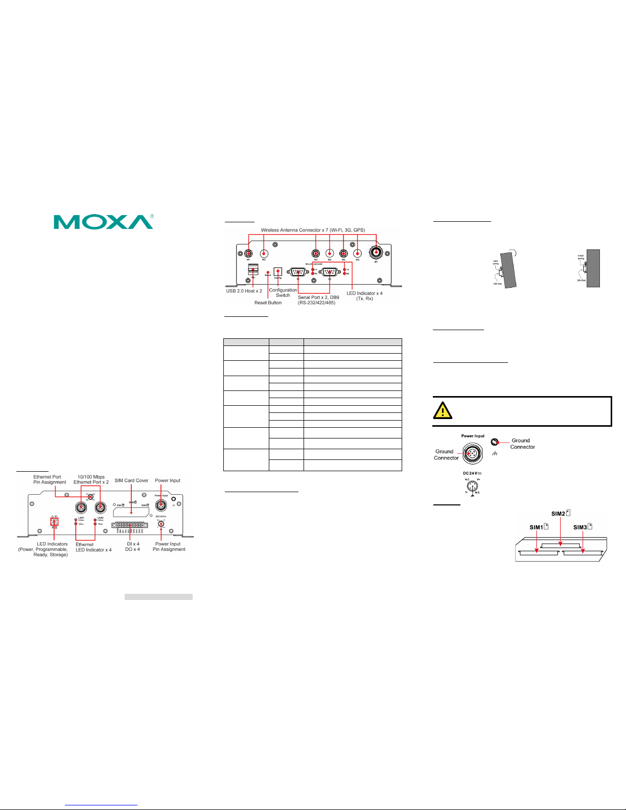
Panel Layout
Refer to the following figu res for the pane l layouts.
Front View
Rear View
LED Indicators
The following t able describes th e LED indicator s located on the
front and rear pan els of the MAR-2000.
LED Name
LED Color
LED Function
Power
Green
Power is on and functioning normally
Off
Power is off, or power error
Storage
Yellow
CF card is detected
Off
CF card is not detected
Ready
Green
The system is ready
Off
The system is not ready
X1
(programmable)
Green
Programmable: no default definition
Off
Programmable: no default definition
LAN1, LA N2
Green
100 Mbps Eth ernet mode
Yellow
10 Mbps Ethernet mode
Off
No activity
P1 Tx, P2 Tx
(on the right of
the DB9 port)
Green Serial port transmitting data
Off Serial port not transmitting data
P1 Rx, P2 Rx
(on the right of
the DB9 port)
Yellow Serial port receiving data
Off Serial port not receiving data
Installing the Mounting Kits
Wall and cab inet mounts
The two metal brackets included with the MAR-2000 can be used to
attach it to a wall or the inside of a cabinet. Using two screws per
bracket , first attach the brackets to the bottom of the MAR-2000.
Next, use two screws (M3 type, torque 4.5±0.5 kgf-cm) per
bracket to attach the MAR-2000 to a wall or cabinet.
DIN rail assemblies
An aluminum DIN rail mou nting assembly is included in th e
package. W hen attaching the rail asse mbly to the MAR-2000,
orient the stiff metal spring towards the top.
STEP 1:
Insert the
top of the DIN rail
into the slot just
below the stiff m etal
spring.
STEP 2:
The
mounting
assembly should
then snap into
place, as shown.
To remove the MAR-2000 from the DIN rail, reverse steps 1 and 2
above.
Connector Description
Power Connector
Connect the 24 VDC po wer line to the MAR-2000’s power input
with the M12 connector. When the MAR-2000 system is ready, the
READY LED will display a steady g reen color.
Grounding the MAR-2000
Grounding and wire routing help limit the effects of noise due to
electromagnetic interference (EMI). Run the ground connection
from the ground screw to the grounding surface prior to connecting
the power.
ATTENTION
This product is intended to be mounted to a well-grounded
mounting surface, such as a metal panel.
There are two ground
connectors on the front
panel of the
MAR-2000.
One is located at the
middle pin of the power
input, the other is beside
the power input. Use either
connector for grounding.
SIM Card
The MAR-2001-T supports 2
c
ellular modu les, and the
MAR
-2002-T supports 3
c
ellular modu les.
Unscrew the
SIM card cover and insert the
SIM card in the
desired slot.
Page 2

– 4 – – 5 – – 6 –
www.moxa.com/support
The Americas:
+1-714-528-6777 (toll-free: 1-888-669-2872)
Europe:
+49-89-3 70 03 99-0
Asia-Pacific:
+886-2-8919-1230
China:
+86-21-5258-9955 (toll-free: 800-820-5036)
2015 Moxa Inc., All Rig hts Reserve d
Ethernet Port
The MAR-2000 comes with 2 10/100 Mbps Ethernet
ports with M12 connectors.
Serial Port
The 2 serial ports (P1 and P2) use DB9 male connectors. Each port
can be configured for use on RS-232, RS-422, or RS-485 networks
from the MAR-2000's management web page. The pin
assignments are shown in the following ta ble:
Pin
RS-232
RS-422
RS-485
(4-wire)
RS-485
(2-wire)
1
DCD
TxDA(-)
TxDA(-)
–
2
RxD
TxDB(+)
TxDB(+)
–
3
TxD
RxDB(+)
RxDB(+)
DataB(+) 4 DTR
RxDA(-)
RxDA(-)
DataA(-)
5
GND
GND
GND
GND
6
DSR – – – 7
RTS – –
–
8
CTS – –
–
Antenna
The MAR-2000 comes with built-in G PS and 3G GSM/HSPA+
modules. The following chart indicates the default configuration of
antenna mounts:
MAR-2001-T
MAR-2002-T
DI, DO
The MAR-2000 has 4 d igital output channels and 4 digit al input
channels. The MAR-2000 Hardware User ’s Manual has detailed
pinout and wiring diagrams.
Reset Button
Press and hold the Reset button continuously for at least 5
seconds to reload the factory default configuration. After the
factory default configuration has been loaded, the system will
reboot automatically. The Ready LED maintains a steady glow once
the system has rebooted.
CompactFlash
The MAR-2000 has a sin gle CompactFlash type I/II slot for
memory expansion. The CF card can be accessed by unscrewing
the panel located on the bottom of the MAR-2000.
The mount point for the CompactFlash filesystem is /dev/sda.
WARNING
Be sure to power off the computer before inserting or
removing the CompactFlash card.
Console Port
The RS-232 console port is a 4-pin header connector located on the
underside o f the motherboard above the CF card socket. As abo ve,
use a screwdriver to remove the panel protecting the CF card to
access the 4-pin RS -232 connector. This serial port is used to
access the console ter minal, and is useful for viewing boot
messages, file system logs, and error messages. Use the
CBL-4PINDB9F-1 00 cable include d with the MAR-2000 to connect
a PC to the MAR-2000’s serial console port.
USB
The MAR-2000 computer features 2 USB 2.0 p orts for external
storage expansion.
Powering on the MAR-2000
To power on the MAR-2000, connect the power cable to the M12
connector and then connect the power adapter.
ATTENTION
T
he shielded g round
should be connected to the center
pin of the power input connector.
Note that it takes approxima tely five minutes for the system to get
ready. Once the system is ready, the Ready LED will light up.
Connecting to the MAR-2000
There are three ways to connect the MAR-2000 to a PC: through
the MAR-2000 management web page, the serial console port, or
by SSH over the network. The COM settings for the serial console
port are: Baudrate=115200 bps, Parity=None, Data bits=8,
Stop bits =1, Flow Control=None.
ATTENTION
Remember to choose the
VT100 terminal type. T
o connect
a PC to
the serial console, use the CBL-4PINDB9F-100
cable that shipp ed with your MAR- 2000.
To use SSH and the MAR-2000 management web page, you will
need to know the MAR-2000’s IP address and netmask. The default
LAN settings are shown below. For initial configuration, you may
find it convenient to use a crossover Ethernet cable to connect
directly from the PC to the MAR-2000.
Default IP Address
Netmask
LAN 1
192.168.3.127
255.255.255.0
LAN 2
192.168.4.127
255.255.255.0
Once the MAR-2000 is powered on and the Ready LED has lit up,
you can open the MAR-2000 management web page. The default
Login and Password:
Login: admin
Password: ad min
NOTE
For additional configuration information, refer to the
MAR-2000 Hardware U ser’s Manual.
 Loading...