

Page 1

ioThinx 4510 Series User’s Manual
Edition 1.0, November 2018
www.moxa.com/product
© 2018 Moxa Inc. All rights reserved.
Page 2

ioThinx 4510 Series User’s Manual
Moxa Americas
Toll
Tel:
Fax:
Moxa China (Shanghai office)
Toll
Tel:
Fax:
Moxa Europe
Tel:
Fax: +49-89-3 70 03 99-99
Mo
Tel:
Fax: +886-2-8919-1231
Moxa India
Tel:
Fax:
The software described in this manual is furnished under a license agreement and may be used only in accordance with
the terms of that agreement.
Copyright Notice
© 2018 Moxa Inc. All rights reserved.
Trademarks
The MOXA logo is a registered trademark of Moxa Inc.
All other trademarks or registered marks in this manual belong to their res pec tive manufacturers.
Disclaimer
Information in this document is subject to c hange witho ut no ti c e and doe s not represent a commitment on the part of
Moxa.
Moxa provides this document as is, without warranty of any kind, either expressed or implied, including, but not limited
to, its particular purpose. Moxa reserves the rig ht to make impro vem e nts and/o r changes to this manual, or to the
products and/or the programs described in this manual , at any time.
Information provided in this manual is intended to be accurate and reliable. However, Moxa assumes no responsibility for
its use, or for any infringements on the rights of third parties tha t may res ult fr om its use.
This product might include unintentional tec hnic al o r typographical errors. Changes are periodically made to the
information herein to correct such errors, and these changes are incorporated into new editions of the public ation.
Technical Support Contact Information
www.moxa.com/support
-free: 1-888-669-2872
+1-714-528-6777
+1-714-528-6778
+49-89-3 70 03 99-0
-free: 800-820-5036
+86-21-5258-9955
+86-21-5258-5505
xa Asia-Pacific
+886-2-8919-1230
+91-80-4172-9088
+91-80-4132-1045
Page 3
Safety Symbols
DANGER
Indicates a high
injury.
WARNING
Indicates a moderate
CAUTION
Indicates a low
injury.
NOTE
Indicates a potential malfunction w hic h, if no t avoided , w ill not r esult in d am age to property .
INFORMATION
This information is important for
-risk, imminently hazardous situation whic h, if no t avoided, will result in death or serious
risk, which, if not avoided can cause a potentially hazardous situation.
-risk, potentially hazardous situation w hi c h, if no t avoided , may res ult in minor or moderate
preventing errors.
Page 4

Table of Contents
1. Preface .............................................................................................................................................. 1-1
Revision History ................................................................................................................................. 1-2
Relevant Models ................................................................................................................................. 1-2
Package Contents ............................................................................................................................... 1-2
Usage Scenarios ................................................................................................................................. 1-2
Hardware and Software Requirements ................................................................................................... 1-3
Safety Precautions .............................................................................................................................. 1-3
Additional Resources ........................................................................................................................... 1-4
2. Product Overview .............................................................................................................................. 2-1
Technical Data.................................................................................................................................... 2-2
Common Specifications ................................................................................................................ 2-2
Appearance ........................................................................................................................................ 2-3
Front View .................................................................................................................................. 2-3
Physical Dimensions .................................................................................................................... 2-4
LED Indicators .................................................................................................................................... 2-5
3. Hardware Installation ....................................................................................................................... 3-1
Wiring System and Field Power ............................................................................................................. 3-2
System Power ............................................................................................................................. 3-2
Field Power ................................................................................................................................. 3-3
Wiring Ethernet Ports .......................................................................................................................... 3-3
Wiring Serial Port(s) ............................................................................................................................ 3-4
Grounding the Unit ............................................................................................................................. 3-5
Connecting the System Power Ground ........................................................................................... 3-5
Connecting the Field Power Ground ............................................................................................... 3-5
Mounting the Unit ............................................................................................................................... 3-6
Installing the Unit on a DIN Rail .................................................................................................... 3-6
Removing the Unit from a DIN Rail ................................................................................................ 3-7
Installing Covers on the Device and the Right-Most I/O Module ......................................................... 3-8
Removing a Cover from the Right-Most Module ............................................................................... 3-8
Horizontal Installation .................................................................................................................. 3-9
Powering on the Unit ........................................................................................................................... 3-9
4. Software Tools .................................................................................................................................. 4-1
Preparing Software Tools ..................................................................................................................... 4-2
Connecting Web Console .............................................................................................................. 4-2
Preparing IOxpress Utility ............................................................................................................. 4-2
Preparing Moxa CLI Configuration Too l ........................................................................................... 4-2
Web Console ...................................................................................................................................... 4-3
Dashboard .................................................................................................................................. 4-4
System ...................................................................................................................................... 4-7
Security ................................................................................................................................... 4-10
Network ................................................................................................................................... 4-13
Module ..................................................................................................................................... 4-13
Serial Port ................................................................................................................................ 4-16
I/O .......................................................................................................................................... 4-19
Internal Register ....................................................................................................................... 4-26
Protocol ................................................................................................................................... 4-27
5. Quick Start Guide .............................................................................................................................. 5-1
Configuring the Unit ............................................................................................................................ 5-2
Login to the Unit ......................................................................................................................... 5-2
Configuring Module Settings ......................................................................................................... 5-2
Changing Device Name ................................................................................................................ 5-4
Changing Username & Password ................................................................................................... 5-4
Configuring Service Settings ......................................................................................................... 5-5
Configuring Account Settings ........................................................................................................ 5-5
Configuring Network Settings ........................................................................................................ 5-6
Configuring Serial Port & IR Settings .............................................................................................. 5-6
Configuring I/O Settings ............................................................................................................... 5-7
Configuring Modbus Address Settings ............................................................................................ 5-8
Configuring SNMP Settings ........................................................................................................... 5-9
Mass-deploying the Settings .............................................................................................................. 5-10
Updating Configuration to Multiple Units ....................................................................................... 5-13
Setting Date and Time to Multiple Units ....................................................................................... 5-14
Monitoring & Operating the Unit ......................................................................................................... 5-15
Monitoring Module & I/O Status .................................................................................................. 5-15
Monitoring Connection Status ..................................................................................................... 5-16
Exiting Safe Mode Status ............................................................................................................ 5-16
Maintaining the Unit .......................................................................................................................... 5-17
Page 5

Backing up Configuration Files .................................................................................................... 5-17
Updating the Firmware ............................................................................................................... 5-17
Restarting the Unit .................................................................................................................... 5-18
Loading Factory Default Settings ................................................................................................. 5-19
A. Appendix ........................................................................................................................................... A-1
Network Port U s ag e ............................................................................................................................ A-2
Modbus/TCP Slave Rules ...................................................................................................................... A-2
Supported Function Code ............................................................................................................. A-2
Exception Code ........................................................................................................................... A-2
System Registers ........................................................................................................................ A-2
45MR-1600 (-T), 16 DIs Registers ................................................................................................. A-3
45MR-1601 (-T), 16 DIs Registers ................................................................................................. A-3
45MR-2404 (-T), 4 Relays Registers .............................................................................................. A-4
45MR-2600 (-T), 16 DOs Registers ................................................................................................ A-4
45MR-2601 (-T), 16 DOs Registers ................................................................................................ A-5
45MR-2606 (-T), 8 DIs, 8 DOs Registers ........................................................................................ A-5
45MR-3800 (-T), 8 AIs Registers ................................................................................................... A-6
45MR-3810 (-T), 8 AIs Registers ................................................................................................... A-6
45MR-4420 (-T), 4 AOs Registers .................................................................................................. A-7
45MR-6600 (-T), 6 RTDs Reg isters ................................................................................................ A-7
45MR-6810 (-T), 8 TCs Registers .................................................................................................. A-8
SNMP Rules ....................................................................................................................................... A-8
RESTful API Rules ............................................................................................................................... A-8
Supported Request Method ........................................................................................................... A-8
GET Request Components ............................................................................................................ A-9
PUT Request Components ............................................................................................................. A-9
RESTful API List .......................................................................................................................... A-9
Exception Code ......................................................................................................................... A-11
Troubleshooting ................................................................................................................................ A-11
Forgot username & password ...................................................................................................... A-12
Forgot IP address of the unit....................................................................................................... A-12
Failed to update firmware ........................................................................................................... A-13
Failed to update configuration ..................................................................................................... A-13
Failed to access the unit through IP address & IOxpress ................................................................. A-14
Failed to Enter System Ready Mode ............................................................................................. A-14
Page 6

1
1. Preface
In this chapter, we explain the scope of and how to use this document.
The following topics are covered in this chapter:
Revision History
Relevant Mo d els
Package Contents
Usage Scenarios
Hardware and Software Requirements
Safety Precautions
Additional Resources
Page 7
ioThinx 4510 Series Preface
1-2
20 to 60°C operating
40 to 75°C operating
Revision History
Version Change Date
V1.0 First Release 2018-11-12
Relevant Models
This document is only applicable to the models lis te d belo w.
Model Name Description
ioThinx 4510 Advanced I/O, Ethernet network adapter, 3-in-1 serial port(s), -
temperature
ioThinx 4510-T Advanced I/O, Ethernet network adapter, 3-in-1 serial port(s), -
temperature
Package Contents
The following items are included in the produc t package.
• The ioThinx 4510 device
• Quick installation guide (Printe d )
• Warranty card
Usage Scenarios
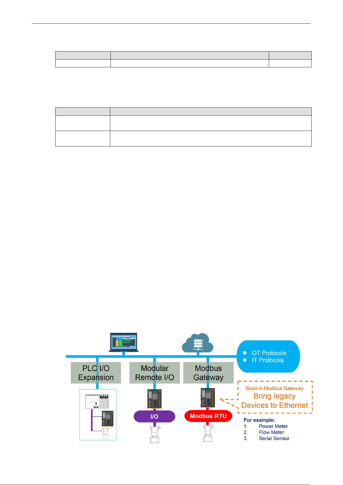
The ioThinx 4510 Series can be used for the following applications:
1. PLC I/O expansion
The ioThinx 4510 Series can be used to expand the number of I/O points on a P LC.
2. Remote I/O
The ioThinx 4510 Series can be accessed by master software, such as SCADA software, using IT or OT
protocols to collect I/O data.
3. Modbus Gateway
The ioThinx 4510 Series has one or more serial ports to connect se rial d evices. It collects serial data using
a Mod bus RTU master p rotocol, which ca n be accessed b y a PLC or mast er software wit h IT or OT protoc ols.
Page 8
ioThinx 4510 Series Preface
1-3
DANGER
Never work on the device while the power source is switched on
power sources to the device
before
DANGER
Disconnect the p
replace components, or disconnect equipment unless the
area is known to be free of ignitable substances.
• If you connect or disconnect the Removable Terminal Block when field power is applied, an electrical arc can
sure that power is removed
• If you connect or disconnect wiring while the power is on, an electr ic al arc can occur . This could cause an
•
WARNING
This unit is sensitive to Electrostatic Discharge, which can cause internal damage and affect operations. Follow
these guidelines when you handle this unit:
•
•
•
•
•
•
WARNING
Check the voltage
the voltage provided by the power source matches
the
Hardware and Software Requirements
You will need the following har dware an d software to use the ioThinx 4510 Series.
• A power source that pr ov ides 12 to 48 VDC, and power w ir es
• A PC running a Windows OS with Chrome installed and an Ethernet cable
• 45MR modules, if available
• IOxpress software utility (op tional)
• Moxa CLI Configuration Tool (optional)
Safety Precautions
Please observe the following safety precautions when installing and using the ioThinx 4510 Series:
performing installation, repair, or maintenance work.
ower when you want to remove or
occur. This could cause an explosion when installed in hazardous locations. En
or the area is nonhazardous before installation.
explosion in hazardous environments. Ensure that power is removed or the area is nonhazardous before
installation.
Do not disconnect the unit unless the power has been disconnected or the area is known to be
nonhazardous. In a hazardous area, the unit must be powered down befo re remov i ng it.
. Disconnect all
Touch a grounded object to discharge potential static.
Wear an approved grounding wristband .
Do not touch connectors or pins on component boards .
Do not touch circuit components inside the equi p ment.
Use a static-safe workstation, if ava ilab le .
Store the device in appropriate static-safe packag ing when not in use.
voltage required by the device.
supplied by the powe r source. Make sure
Page 9
ioThinx 4510 Series Preface
1-4
WARNING
Check the voltage or current of the sensors or loads.
sensors or loads co
WARNING
Connect your device to an earthed ground.
CAUTION
Do not use the device if the device is already
at
your devices function properly
CAUTION
Do not attempt to repair the
return the device to Moxa’s
customer
.
service department. Attempting to repair the device yourself could invalidate the device’s warranty
rresponds to the specifications of your 45M module before you connect the device.
.
device yourself. If your device needs to be r epai r ed,
Additional Resource s
Make sure the voltage and/or current indicated on the
damaged. Replace defective or damaged d evices to ensure th
Refer to the following documents for additio nal info rmation.
• Datasheets for the following products:
ioThinx 4510 Series
ioThinx 4500 Series (45MR) Modules
• User’s Manual for the following produc ts :
ioThinx 4500 (45M) Module Series
Moxa CLI Con figuration Tool
Page 10

2
2. Product Overview
In this chapter, we give an overview of each of the 45MR modules.
The following topics are covered in this chapter:
Technical Data
Common Specifications
Appearance
F ront View
Phy s ic a l D im e ns ions
LED Indicators
Page 11

ioThinx 4510 Series Product Overview
2-2
Input/Output Int erface
Expansion Modul es
Note: Compatible with 45MR Series only
Ethernet Interface
10/100BaseT(X) Ports (RJ45 connector)
Ethernet Software Features
Industr ial Protocols
Modbus TCP Server (Slave)
RESTful API
SNMPv1/v2c/v3
Serial Interface
Serial Standards:
Connector:
Wiring: 16 to 28 AWG
Serial Software Features
Industrial Protocols:
System Power Parameter
Input Voltage:
Connector:
Wiring:
Field Power Parameter
Input
Connector:
Wiring:
Physical Characteristics
Dimensions:
Installation: DIN-rail
Environmental Limits
Operating Temperature:
Standard Models:
Wide Temp. Models:
Technical Data
Common Specifications
: Up to 32
: 2
:
1 x RS-232/422 or 2 x RS-485 (2-wire)
Removable Terminal block
Modbus RTU Client (master)
12 to 48 VDC
Removable terminal block
12 to 26 AWG
Voltage: 12/24 VDC
Removable terminal block
12 to 26 AWG
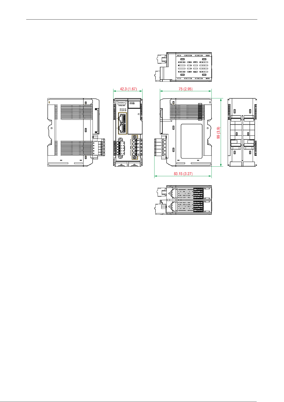
42.3 x 99 x 75 mm (1.67 x 3.9 x 2.69 in)
-20 to 60°C (-4 to 140°F)
-40 to 75°C (-40 to 167°F)
Page 12
ioThinx 4510 Series Product Overview
2-3
Appearance
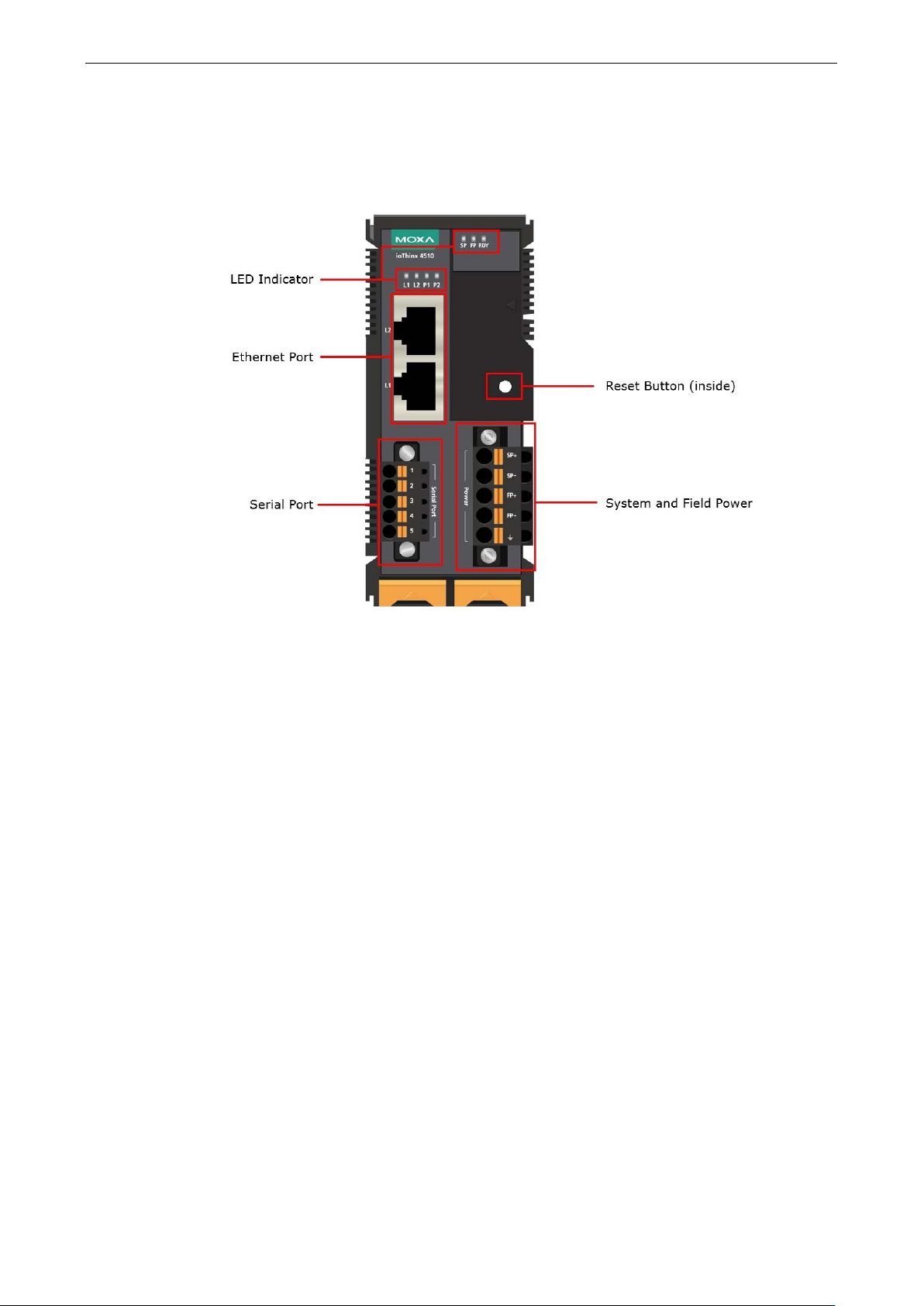
Front View
Page 13
ioThinx 4510 Series Product Overview
2-4
Physical Dimensions
Unit: mm (in)
Page 14

ioThinx 4510 Series Product Overview
2-5
Power
Off: power off
NOTE
DO NOT DISCONNECT
INFORMATION
Refer to
in the troubleshooting section for addition information
about
LED Indicators
Labeling Indication LED Qty LED Color LED Action
SP
System
1 Green
On: power on
FP Field Power 1 Green
RDY
L1/L2 Ethernet 1 for each Green/Amber
P1/P2 Serial 1 for each Green/Amber
System
(Kernel)
Failed to Enter System Ready Mode
the system recovery process.
1 Green/Red
THE POWER OR NETWORK CABLE when the RDY LED is blinking slowly.
On: power on
Off: power off
Green: system ready
Green slow blinking: booting up
Red: system error or module mismatch
Red slow blinking: loading factory def ault settings,
upgrading firmware, or system recovery
Red fast blinking: safe mode
Off: power off
Green: 100mb
Amber: 10mb
Blinking: data transmitting
Off: disconnected
Green: Tx
Amber: Rx
Non-simultaneous blinking: data transmitting
Off: disconnected or no data transmitting
Page 15

3
3. Hardware Installation
In this chapter, we describe how to install the 45MR modules.
The following topics are covered in this chapter:
Wiring System and Field Power
S y s te m Power
F i e ld Pow er
Wiring Ethernet Por t s
Wiring Serial Port(s)
Grounding the Unit
C o nne cting the System Power Ground
C o nne cting the Field Power Ground
Mounting the Unit
Installing the Unit on a DIN Rail
R e moving the Unit from a DIN Rail
Installing Covers on the Device and the Right-Most I/O Module
Removing a Cover from the Right-Most Module
Horizontal Installation
Powering on t he Unit
Page 16
ioThinx 4510 Series Hardware Installation
3-2
NOTE
P
power supply. If only one of the
power
NOTE
W
are isolated
from each other
between them is recommended.
NOTE
Install the 45MR
the module where the power consumption would be exceeded.
NOTE
To avoid damaging your devices, r
at
the same time
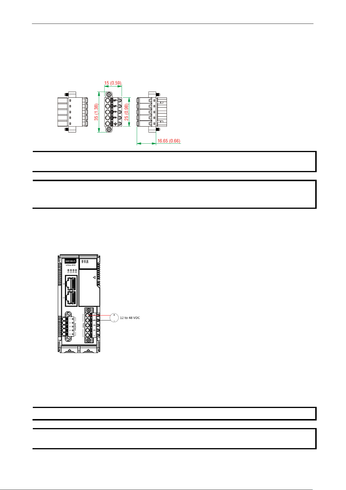
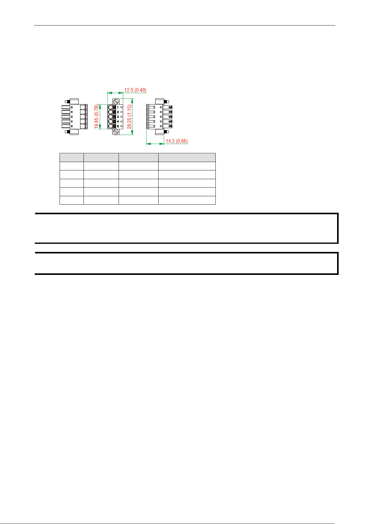
Wiring System and Field Power
Wire range: 12 to 26 AWG (Ferrule diameter: 2.0 to 0.4 mm)
Wire strip length: 10 mm
Unit: mm (in.)
owering the unit requires connecting both the s ystem and field power to the
sources is connec te d, the device may not work properly.
e recommended using different power supplies to ensure that the system power and field power
. If using the same power supply for system power and field power, 3 KV or above isola tio n
System Power
This device requires a 12 to 48 VDC system power input. The system power powers this device and the
expansion modules via an inte r na l b us , which is g alv a nic ally c o nnecte d to the syste m power supply.
The amount of system current required to support an expansio n mod ule is 1 A. If more modules and more
power consumption is needed, an additional power module (45MR -7210) is required. Below is an example:
• 10 x 45MR-1600 (59.4 mA) = 594 mA
• 5 x 45MR-3810 (187 mA) = 935 mA
The total system current is 1.594 A, which is greater than 1 A. Therefore, an additional 45MR-7210 is needed.
-7210 to the left hand side of
eset all power su pplies c onnect ed to this device and 45MR-7210 modules
.
Page 17
ioThinx 4510 Series Hardware Installation
3-3
NOTE
The 12/24 VDC field power supply can be connected directly to 45MR modules. If more connection points are
needed, purchase 45MR
3
Rx+ (receive)
Field Power
This device provides 12/24 VDC field power input, which is a passive power supply without protection and the
maximum current output is 2 A.
-7820 (8 x FP+ and 8 x FP-) modules.
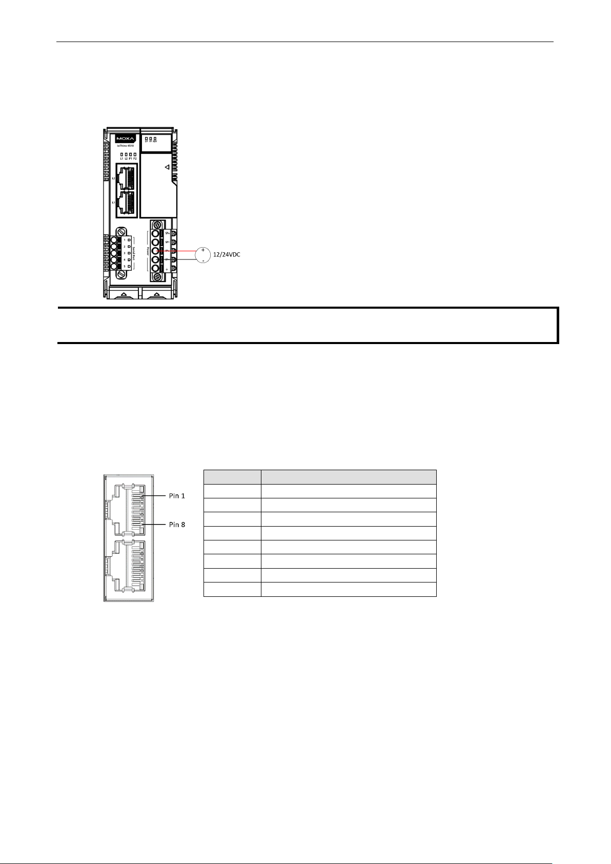
Wiring Ethernet Ports
The maximum cable length of a 10/100BaseT connection is usually stated as 100 m (350 feet), but the actual
limit for your application could b e longer or shorte r d epe nding on the amount of electrical noise in the
environment. To minimize the amount of noise, Ethernet cables should not run parallel to power cables or other
types of cables that generate electrical noise. The following diagram and table shows the pin assignments for
the RJ45 Ethernet ports:
Pin Media Direct Interface Signal
1 Tx+ (transmit)
2 Tx- (transmit)
4 Not used
5 Not used
6 Rx- (receive)
7 Not used
8 Not used
Page 18
ioThinx 4510 Series Hardware Installation
3-4
NOTE
Connect the signal
device units. For insulated wire (shielding cable)
electrical noise, connect the cable shield
drain wire to the chassis ground.
NOTE
To ensure that wires are
of insulation off the
ends of the wires before connecting them to the terminal b lock
Wiring Serial Port(s)
Wire range: 16 to 28 AWG (Ferrule diameter: 1.2 to 0.3 mm)
Wire strip length: 9.0 mm
Unit: mm (in.)
Pin RS-232 RS-422 RS-485 (P1/P2)
1 TXD TXD+ DATA1+
2 RXD TXD- DATA13 RTS RXD+ DATA2+
4 CTS RXD- DATA25 GND GND GND
common pin (e.g. GND pin on the serial port pin assig nme nt) betw een e ach of the serial
that is used to reduce
securely connected to terminal block connectors, strip 7 to 9 mm
.
Page 19

ioThinx 4510 Series Hardware Installation
3-5
CAUTION
F
Grounding the Unit
This device has two ground pins. One pin is for system power and the other pin is for field power.
Connecting the System Power Ground
The system power ground connector is at the back of the unit. Once the device has been installed on a DIN rail,
the system power ground connector will connect to the DIN rail.
or surge protection, connect the DIN rail to earth ground.
Connecting the Field Power Ground
Connect the field power ground pin ( ) to your field power ground.
Page 20
ioThinx 4510 Series Hardware Installation
3-6
CAUTION
Be sure to
codes dictating the maximum current allowable for each wire size. If currents exceed the maximum rating, the
wires will overheat
equipment. For safety reasons, we recommend
using 2
DANGER
Never install the device while the power source is switche d on
note the maximum possible current for each power wire and common wire. Observ e all elec trical
, which could cause serious damage to your
mm diameter wire to connect to the power supply (e.g., 12 AWG).
Mounting the Unit
In this section, we describe how to mount the device on a DIN rail and how to unmount the device from a D IN
rail.
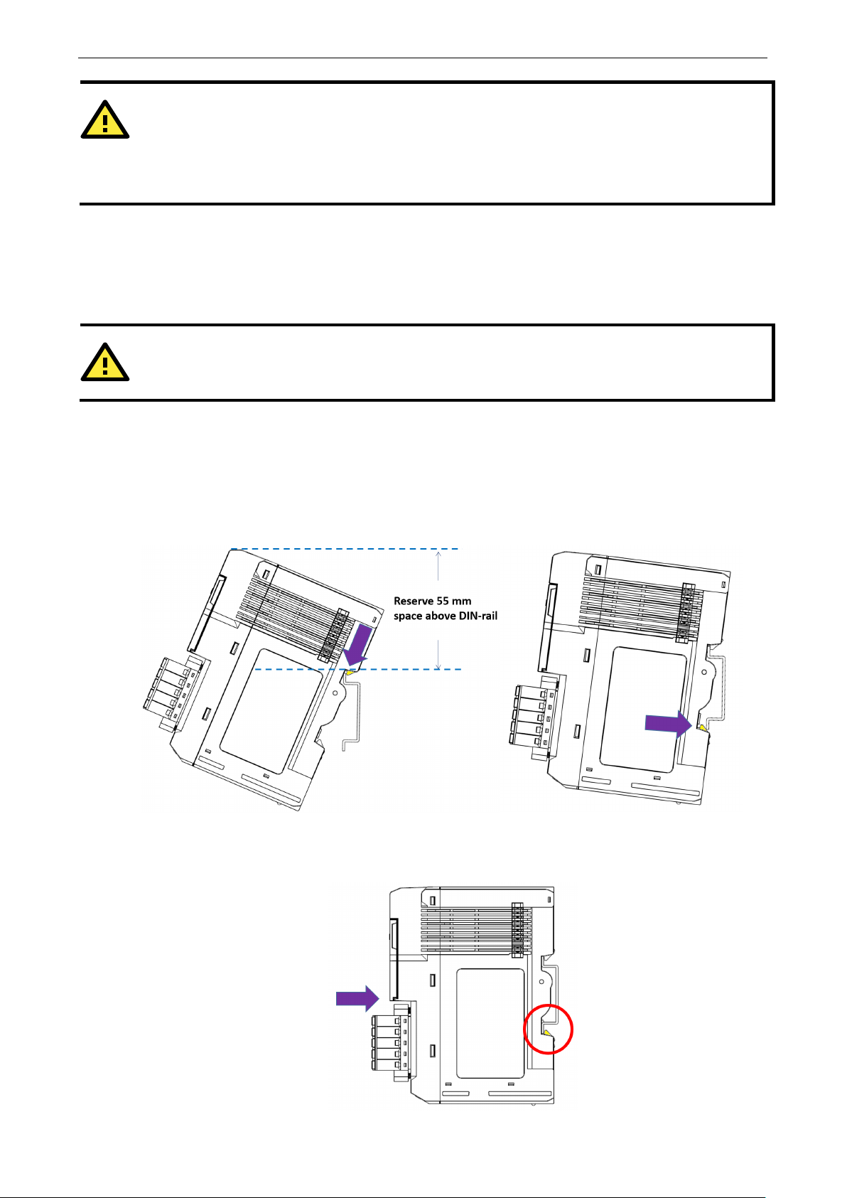
Installing the Unit on a DIN Rail
Take the following steps to install the unit on a DIN rail.
Step 1: Hook the mounting clip of the unit onto the DIN rail, and then lo wer the clip onto the DIN rail. At least
55 mm of space above the DIN rail should be kept free to ensure that the ins ta llation can be done correctly.
.
Step 2: Push the unit towards the DIN rail until the end of the mounting clip snaps into place.
Page 21

ioThinx 4510 Series Hardware Installation
3-7
INFORMATION
the I/O module is inserted into the correct position, the connection between the internal bus and
the previous module is established.
NOTE
D
before removing the
device
When
Removing the Unit from a DIN Rail
Take the following steps to remove the unit from a DIN rail.
Step 1: Use your finger to pull the release tab on the lower part of the module.
Step 2: Press the release tab (item 1 in the figure) and then remove the CPU module from the DIN rail (item
2 in the figure).
isconnect all connections, including Ethernet, serial, and power cables, from the device
from the DIN rail.
Page 22
ioThinx 4510 Series Hardware Installation
3-8
NOTE
The covers provide protection against
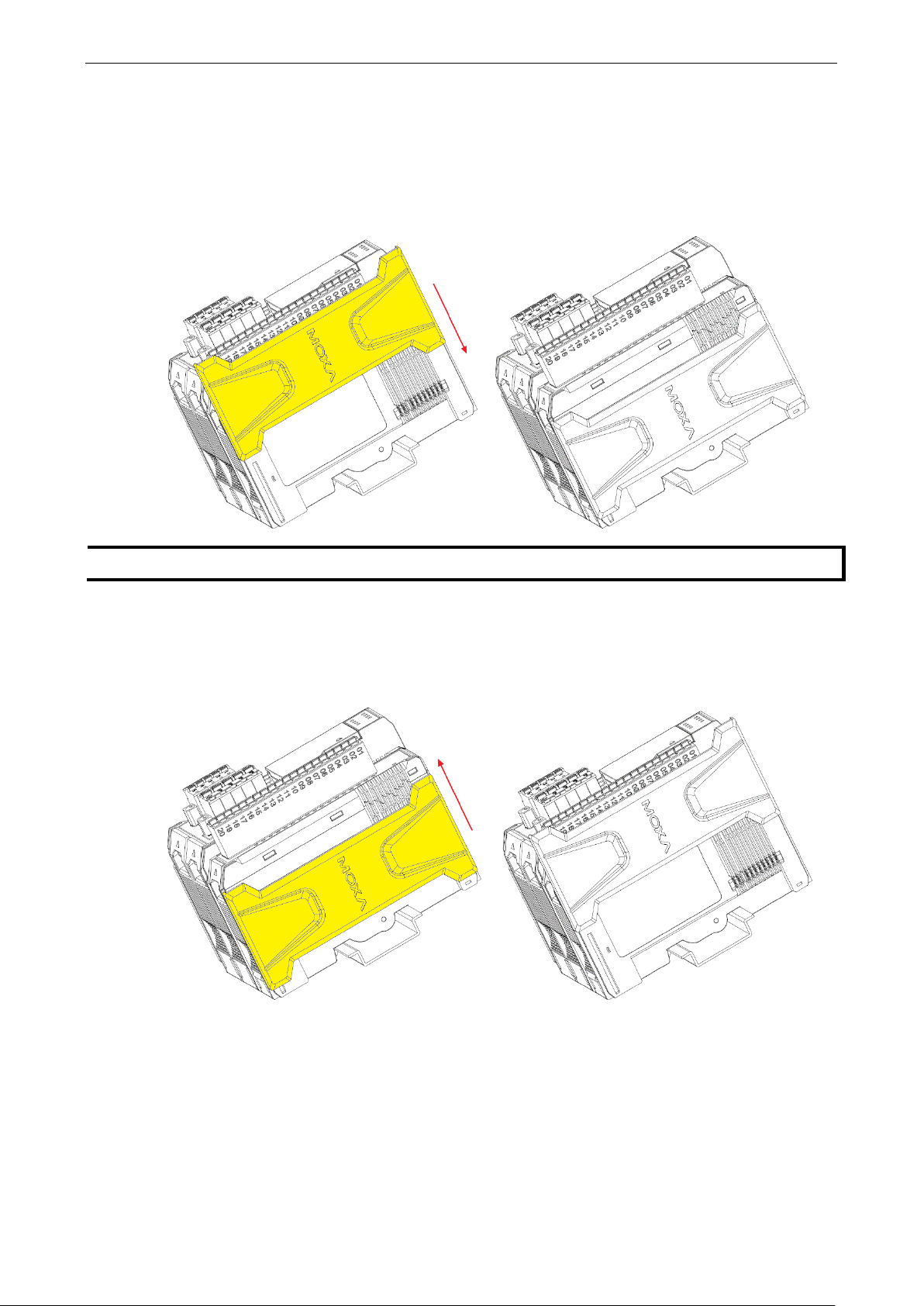
Installing Covers on the Device and the Right-Most I/O Module
Insert the covers on the left side of the device and on the right side of the I/O module that is installed furthest
to the right. Make sure the covers cover the internal bus of the module.
electrostatic discharge.
Removing a Cover from the Right-Most Module
Before adding a new module to the right-most module, remove the cove r fir s t. Plac e your hand on the cover
and slide it up as indicated in the diagram below.
Page 23
ioThinx 4510 Series Hardware Installation
3-9
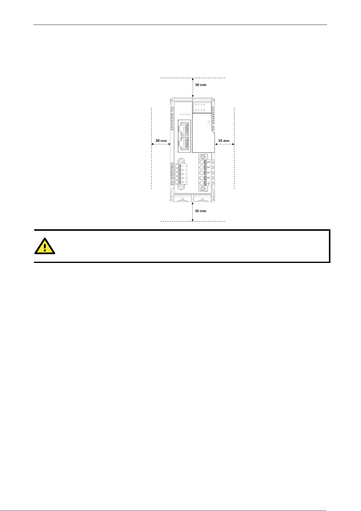
CAUTION
DO NOT install the device vertically
Horizontal Installation
Before installing the device, ensure there is enoug h space aro und the de v ice so that it can diss ipate heat. In
order to ensure the device works properly, we suggest reserving the space shown in the figure below.
, as the fan-less heat dissipation design will no t perf orm as inte nded.
Powering on the Unit
After turning on the power supply, it will take 5 to 10 seconds for the operating system to boot up. The green
Ready LED will illuminate continuously until the operating system is ready.
Page 24

4
4. Software Tools
In this chapter, w e introduce which software tools can be used with this dev ic e .
The following topics are covered in this chapter:
Preparing Software Tools
C o nne cting Web Console
Preparing IOxpress Utility
Pr e paring Moxa CLI Configuration Tool
Web Console
Dashboard
System
Security
Network
Module
S e r i al Por t
I/O
Internal Register
Protocol
Page 25

ioThinx 4510 Series Software Tools
4-2
INFORMATION
Type
. If the IP address is not available, use
the IOxpress utility to search
by holding down the
RESET button to access the device through
NOTE
The
Preparing Software Tools
Connecting Web Console
The Web Console is already embedded in this device. Use the web con sole to check the device status, configure
settings, or update the firmware of the device. Follow the steps be low to conne c t to the web console.
1. Connect the devic e to your PC thro ugh an Ethernet cable.
2. Power on the unit.
3. Open a web browser (Chrome is recommended) on y ou r PC, and type the default IP address shown on the
model label of the unit.
in the IP addres s (if the IP address is not set by default)
for the device, or load the factory default settings
Preparing IOxpress Utility
The IOxpress Utility can be downloaded from the Moxa website at www.moxa.com. After downloading the file,
unzip it and run setup.exe. The installation pro gr a m will g uid e yo u thro ugh the ins tall ation process.
The IOxpress utility c a n be used for any of the purposes below. Multiple devices can be used at one time.
• Update configurations to the device
• Get configurations from the device
• Update firmware of the device
• Set device date and time
• Restart the device
• Load the factory default settings
Refer to the Mass-deploying the Settings section for detailed instructions.
ioThinx 4510 Series is only compatible with IOxpress v2.2 or later.
the default IP address.
Preparing Moxa CLI Configuration Tool
Moxa CLI Configuration Tool (MCC_Tool) can be downloaded from the Moxa website at www.moxa.com. After
downloading the file, unzip it and run setup.exe. The installation program will guide you through the installation
process.
It is a command line tool that provides the following functions to manage field devices.
• Report firmware versions
• Upgrade firmware
• Import/export configura tio n files
• Change password
Management tasks can be performed ac cording t o which devi ces the u ser requir es (1 for single device or 1 for
multiple devices) and across differe nt s ubnet ne tworks.
Refer to Moxa CLI Configuration Tool User’s Manual for detailed instructions.
Page 26

ioThinx 4510 Series Software Tools
4-3
INFORMATION
Whenever any configuration is modified, the
Save &
Restart
NOTE
For security
unattended.
Web Console
The Web Console is the main software tool to configure, monitor , and operate a device. If mass deploying to
multiple devices is required, use IOxpr ess util ity ins te a d .
The Web Console is divided into three regions :
1. Title Panel: It provides Login, Save & Restart, and Logout functions.
2. Menu panel: It provides access to config ure the func tions or services.
3. Web page panel: The web page associated with the function selected in the Menu panel.
to make the changes effective.
reasons, click Logout when no longer accessing this device. DO NOT leave the web console
Save & Restart will become red and blink. Click
Page 27
ioThinx 4510 Series Software Tools
4-4
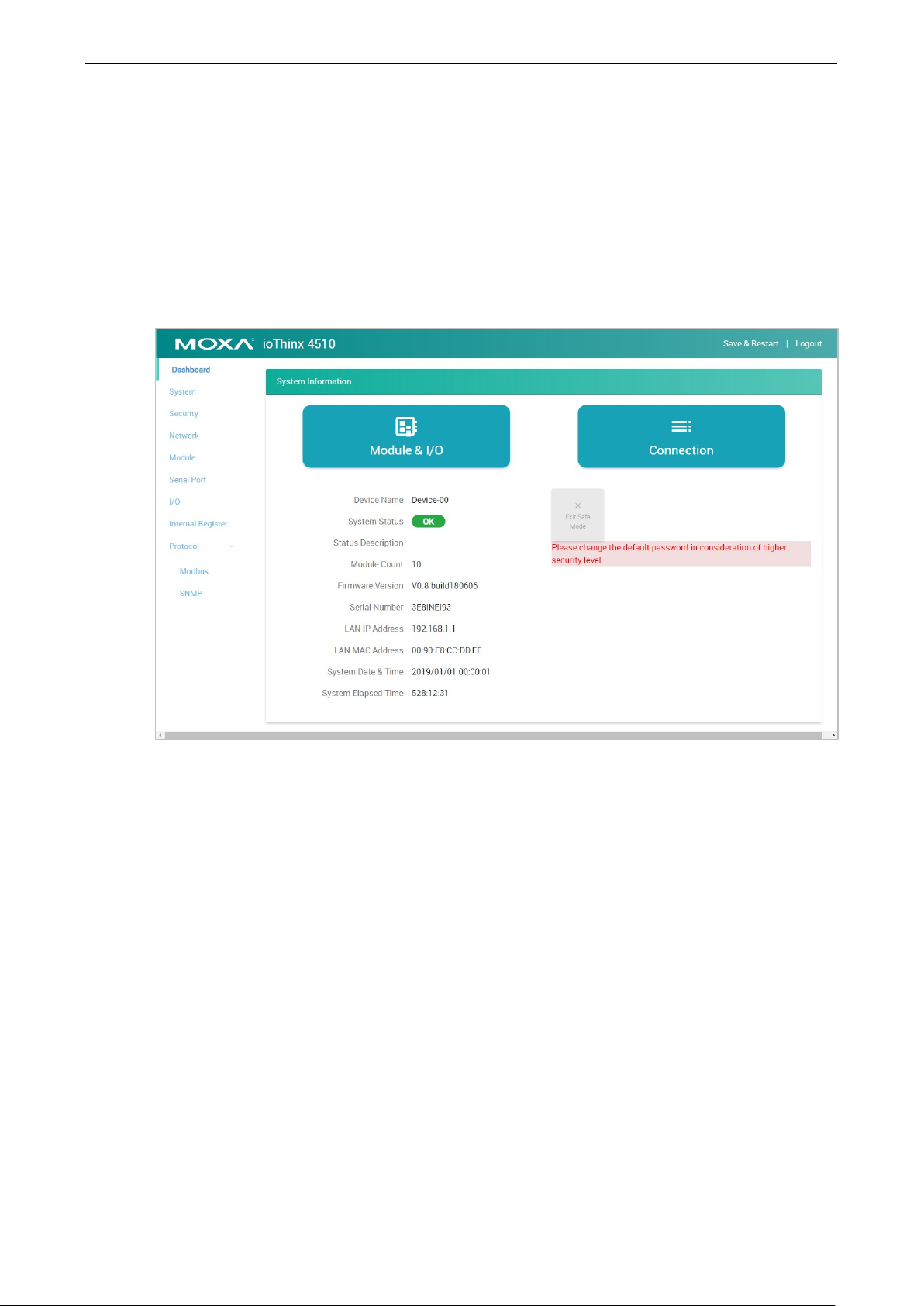
Dashboard
The dashboard provides information about the system, modules, I/Os, and the connection status. It also allows
you to exit the safe mode status or to change the I/O status.
System Information
The one page system information provides detaile d inf or mation for this device. For information regarding
modules and I/Os, click Module & I/O to get the detailed information. For the status of external connections,
click Connection to get the detailed information.
Exit Safe Mode: Manually exit the safe mode status of this device. Refer to the Security section for more
information about the Safe Mode function.
Page 28

ioThinx 4510 Series Software Tools
4-5
Module & I/O
The Module & I/ O provides information about modules and I/Os status. It also allows you to change the I/O
status.
Module Drop-Down List: It lists all of the I/O modules of this device. Select the specific module for its module
and I/O information.
Locate: Identify the physical location of the module and the module’s status L ED will b link gre e n.
DI Channel (DI Mode): It shows the s tatus of this c ha nnel. No operation is allowed.
DI Channel (Counter Mode): It shows the status of this channel. Type a value between 0 and 4294967295,
and then click SET to set the current counter value. Click RUN or PAUSE to change the counter status.
DO Channel (D O Mode): It shows the status of this channel. Click ON or OFF to change the DO status.
Page 29

ioThinx 4510 Series Software Tools
4-6
DO Channel (Pulse Mode): It show s the status of this channel. Click START or STOP to change the pulse
output status.
Relay Channel: It shows the status of this c hanne l. C lick ON or OFF to change the relay status.
AI Channel: It shows the status of this channel. Click RESET to reset the minimum and maximum values.
RTD Channel: It shows the status of this channel. Click RESET to reset the minimum and maximum values.
TC Channel : It s how s the status of this channel. Click RESET to reset the minimum and maximum values.
Apply the reference temperature value in the calib ration field and click SET to execute calibration.
Connection
The connection page shows the connection status from other hosts. This information can assist you with
managing your devices.
Page 30

ioThinx 4510 Series Software Tools
4-7
INFORMATION
This device does not have a battery. Therefore, if the device is powered off, the system date and time
will have to be set again.
after
rebooting.
System
This section introduces the functions of the device’s system.
Device Settings
Device Name: Set the name of this device (max length = 16, '.' is not allowed).
Language: Select the language of the web console.
Time Settings
System Dat e & Ti m e: Select the date for the device. Click Set Time to set the time of the device.
Enable NTP Server: Click the checkbox to enable date and time synchronization with the NTP sever.
NTP Server: Set the URL or IP address of the NTP server.
Sync Interval: Set the synchronization interval with the NTP s ever (unit: min(s), 1 t o 43200, default = 1440).
If the NTP server is not available, set the date and time of the device
Page 31
ioThinx 4510 Series Software Tools
4-8
Output channels: set the channel status
Status: Red fast blinking until the error flag
NOTE
To exit
"watchdogAlarmFlagClear" register through Modbus. Otherwise, output channels cannot be controlled via any
access e.g. RESTful API or web console.
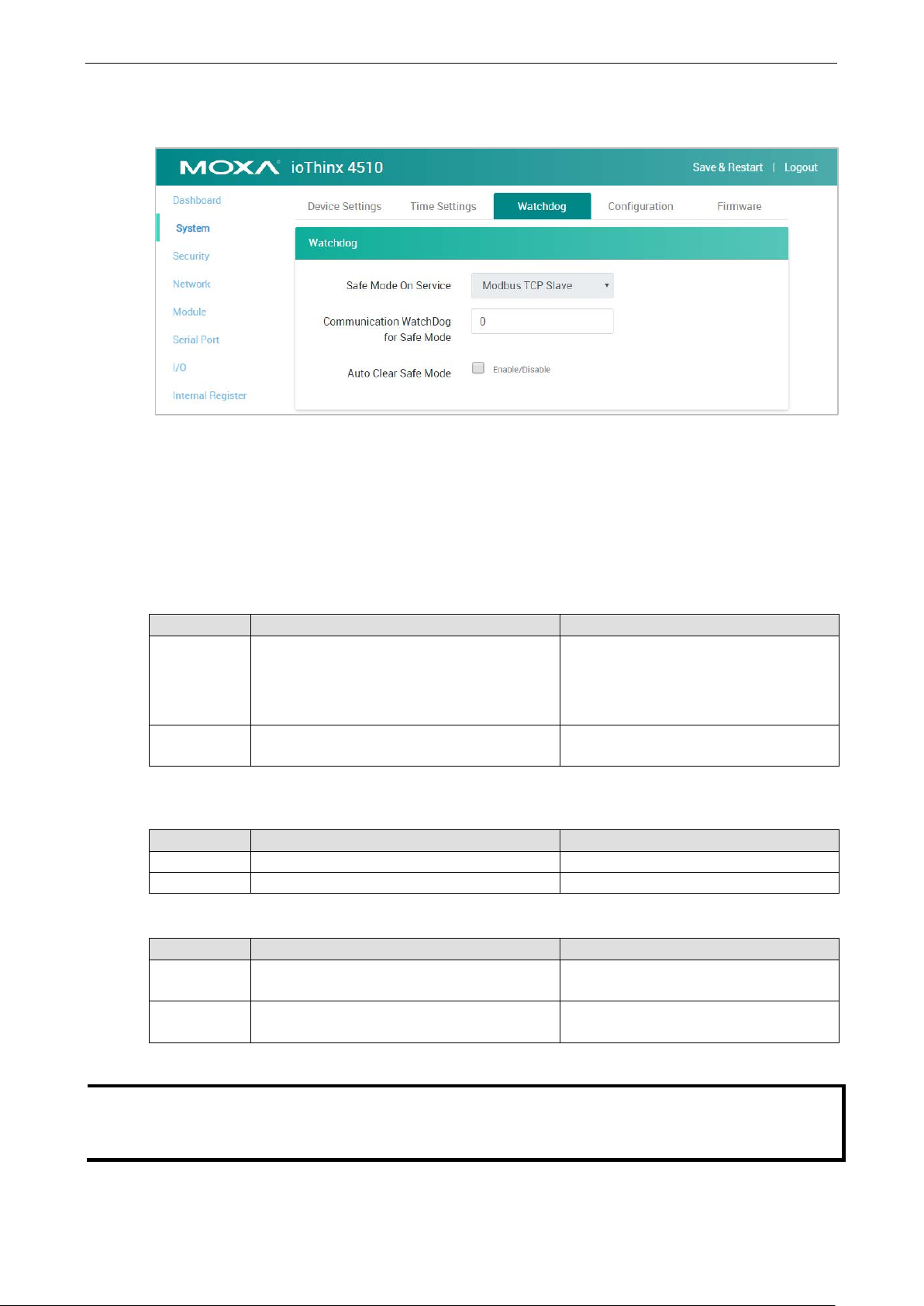
Watchdog
Safe Mode o n S er v ice: Select the service that you want to link the watchdog to in order to keep monitoring
the connection status (option: Modbus TCP Slav e ).
Communication Watchdog for Safe Mode: The timeout value when the master of Safe Mode on Ser vi c e
is disconnected (unit: sec(s), 0 to 65535, 0 is disable).
Auto Clear Safe Mode: Click the checkbox to enable or disable automatically clearing the safe mode status.
Once the communication watchdog is timeout, the safe mode will be enabled. The behavior of ioThinx 4510 and
45MR modules are listed below:
ioThinx 451 0 45MR modules
Behavior • Wait for Modbus/TCP Master’s re-connection
• Output channels cannot be controlled via any
access e.g. RESTful API or web console
LED status RDY: Red fast blinking Status: Red fast blinking (applied to the
Once the connection is recovered, the behavior of the ioThinx 4510 and 45MR modules are listed below.
1. Auto Clear Safe Mode: Enabled
ioThinx 451 0 45MR modules
Behavior Recovered to normal status Recovered to normal status
LED status RDY: Green Status: Green
2. Auto Clear Safe Mode: Dis abled
ioThinx 451 0 45MR modules
Behavior Status will remain on safe mode until the safe
mode flag is cleared.
LED status RDY: Red fast blinking until the error flag is
cleared manually
• Input channels: no change
•
according to pre-defined safe mode
settings
modules which have output channels only)
Status will remain on safe mode until the
safe mode flag is cleared.
is cleared manually
the safe mode status, click the "Exit Safe Mode" button on the dashboard or type "0" to the
Page 32

ioThinx 4510 Series Software Tools
4-9
NOTE
Do not disconnect the power or network cable
INFORMATION
Back
Configuration
Select File: Click Browse to select a configuration file to upd ate the device.
Update network settings (IP, Gateway, etc.): Click the checkbox if the network settings need to be
updated.
Update to Device: Click Update to update the firmware to the device.
Get from Device: Get the configuration file of the device.
Load to Default: Load the factory default settings of the current firmware version.
up the configuration file before lo ading the f acto ry default configurations.
during the update process.
Firmware
Firmware: Click Browse to select a firmware file to update the device.
Update to Device: Click Update to update the firmware to the device.
Page 33

ioThinx 4510 Series Software Tools
4-10
NOTE
Do not disconnect the power or network cable during the update
NOTE
This
system will load the backup firmware automatically to overwrite the corrupted one. When the system is in
recovery mode, the RDY
recovery
process
INFORMATION
The update process cannot be canceled after "Update" is clicked.
INFORMATION
Back
NOTE
Do not
security of the
device, we suggest configuring secur i ty se tting s prior to other settings.
NOTE
If all services are disabled, this device will no longer be accessible, and you will need to load the factory default
configuration
device supports firmware automatic reco v ery func tio n. I f the fir mware in the device is corrupted, the
is underway. After the recovery process is complete, you can update the firmware again.
Security
The Security section allows you to manage the security policy of the device.
Service Settings
expose the device to the public Internet without any security protection. To increase the
process.
LED will slowly blink red. DO NOT DISCONNECT the power cabl e w he n the
up the configuration file before updating the device f i r mware.
Enable/disable services to preve nt unwanted access. The Default configuration enable s Web Serv er.
s to access the device.
Page 34

ioThinx 4510 Series Software Tools
4-11
NOTE
Change the default password in
INFORMATION
The default username is admin, and the default passwor d is moxa.
User Settings
Enable/Disable user type, or config ure the username and password for Administrator, Operator, and Users.
Type: Select a user type to change the username and password.
Enable: Enable or disable the type you select.
New Username: It allows you to change the username of the selected user type (Must be 1 to 30 characters
in length. Letters, numbers, and symbols are allow ed , but not spa c e s ).
Admin Password: T ype the password for the administrator to gain authorization to ma ke changes.
New Password: It allows you to change the password of the selected user type (Must be 1 to 30 characters
in length and include at least one number and one symbol. Letters, number s , and symbols are allowed but
spaces are not).
Confirm Password: Type in your new password ag ain.
order to enhance security when you first login.
Page 35

ioThinx 4510 Series Software Tools
4-12
Account Settings
Idle Timeout: The timeout value when the user account is idle (unit: min(s), 0 to 1440 mins, default: 5 mins)
Note: 0 for disabled.
Retry Failure Threshold: The maximum number of retries for the user account to log in (unit: time(s), 1 to
10 times, default: 5 times).
Lockout Time: The timeout value for when the user account will be locked due to reaching the retry failure
threshold (unit: min(s), 1 to 60 mins, default: 5 mins).
Login Failure Mess ag e: Create the message shown on the login webpage after the user account fails to log
in (character limit = 200).
System Use Notificatio n: D efine the messa ge shown on the login webpage when the user account connects
to the Web Console (character limit = 200).
Access Control
Use IP Address/Netmask combinations to control which devices can access the device.
Page 36

ioThinx 4510 Series Software Tools
4-13
INFORMATION
The
same IP
address
Network
This section introduces the Network settings function.
LAN Settings
IP Configurati on: Configure the following settings if Static IP is selected. If DHCP is s elected, the following
settings are not allowed (option: Static IP or DHCP).
IP Address: Set the IP address of the device (0 to 255).
Netmask: Define the logical subdivision of an IP network and specify the network's available hosts (0 to 255).
Gateway: Def i ne the router that can route the network traffic to the other network or Internet (0 to 255).
DNS1 and DNS2: Define DNS server(s) that can translate URL to IP address (0 to 255).
Module
This section introduces the Module s e tting s f unc tio n.
IP address of the device must be unique. Two devices in the network cannot share the
as it causes an IP address conflic t.
Page 37

ioThinx 4510 Series Software Tools
4-14
Edit: Click this butto n to enter edit mod e .
Save Settings: This button only appears in edit mode. Click this button to finish module settings and exit edit
mode.
Cancel: This button only appears in edit mode. Click this button to cancel module settings and exit edit mode.
Auto Matching : Click this button to automatically match all configured modules with all detected modules.
Load Default : C lic k this b utto n to lo ad the default settings of all configured modules.
Reload : Click this button to reload the mod ule setting s before entering edit mode.
Slot: The slo t position of the detected module.
Detected Mo d u l e: The ph ysical module detected by the system. The yellow arrow allows you to insert the
specific module into the configured module.
Configured Module: The module settings for the detected module. A unique module name is required in the
textbox (max. length = 16, “.” is not allowed).
The delete icon appears when you place your mouse over the place indicated below. It allows you to delete the
configured module.
The drag icon allows you to drag the configured module and drop it to the position you need.
Page 38

ioThinx 4510 Series Software Tools
4-15
NOTE
The detected module should match the config ured mod ule . Otherw is e , the Web Console will no t allow you to
configure other settings.
NOTE
The detected module should match the config ured mod ule . Otherw is e , the Web Console will no t allow you to
click
INFORMATION
Use
INFORMATION
Once the setting of a configured module is changed, the configured module will be highlighted by an
orange
INFORMATION
highlighted by
Finish.
Auto Matching to quickly match the configured module with the dete cted module.
rectangle.
If the configured module does not match the detected module, the c onfigured module will be
a red rectangle.
Page 39

ioThinx 4510 Series Software Tools
4-16
NOTE
The Port 2 tab is only available when the
Serial Port
This section introduces the serial por t settings function.
Port 1/Port 2
Click the tab to configure the settings of Port 1 or Port 2.
Mode: The standard of the serial device connected to this port (option: RS-232, RS-422, or RS-485 2-Wire).
Baudrate: The data transmission rate (option: 300, 1200, 2400, 4800, 9600, 19200, 38400, 57600, or
115200 bps).
Parity: The method of detecting errors in transmiss io n (op tion: Ev e n, Odd, or No ne).
Data Bits: The data bits in each character (option: 5, 6, 7, or 8).
Mode of the Port 1 is RS-485 2-Wire.
Stop Bits: The stop bits sent at the end of every character (option: 1 or 2).
Flow Control: The handshaking method (option: None, RTC/CTS, or XON/XOFF).
Page 40

ioThinx 4510 Series Software Tools
4-17
NOTE
A maximum of four Modbus RTU devices can be connected to one serial port
.
Modbus RTU Device
Device Drop-Down List: It shows the device name of the Modbus RTU devices. Select one of the devices to
configure its settings. The green ico n shows tha t data colle ction from the device is enabled.
Enable Device: Click the checkbox to enable data collection from the device. The icon beside the Mod b us
device in the Device Drop-Down List will change from red to green after being enabled.
Device Name: Name of the Modbus device (max. length = 16; “.” is not allowed).
Device ID: The device ID of this Modbus device (options: 1 to 247; default: 1).
Advanced Button: Click this button to show/hide the following settings.
Delay between Polls: The delay time after polling the Modbus register(s) of the Modbus device (unit: 100 ms;
100 to 3600000; 0 disabled; default: 10).
Polling Timeout: The timeout value when polling data from the Modbus device (unit: 100 ms; 0 to 30000;
default: 30).
Polling Retries: The maximum number of retries after a polling timeout occurs (options: 0 to 10; default: 3).
when the RS-485 mode is selected
Page 41

ioThinx 4510 Series Software Tools
4-18
Modbus RTU Device Profile
Click Add New Profile to create a profile of the selecte d d evi ce.
After creating a new profile, configure the se tting s of the profile.
Profile Name: Name the profile of the Modbus device (max. length = 16; “.” is not a llowed ).
Point Type: Set the corresponding Modbus point type setting (option: 01: Coil Status (R/W), 02: Input Status
(R), 03: Holding Register (R/W), or 04: Input Registe r (R ))
Start Address: Define the start address of this Modbus tag (0 to 65535).
Length: Define the length of the coil (1 to 2000) or the register (1 to 125).
Scan Rate: De f i ne how quick ly to poll the profile data (unit: 100 ms; 100 to 3600000; default: 10).
IR Type: Set the internal register data type (option: BOOL, WORD, DWORD, or FLOAT).
IR Start Index: Set the start number of the internal register for storing data. It only allows you to select
available internal registers , depe nd ing o n the length you define.
Swapped Value: Select a data conversion option.
IR Type Option
WORD 1. HiByte & LoByte
2. LoByte & HiByte
DWORD 1. HiWord & LoWord
2. LoWord & HiWord
FLOAT 1. HiWord & LoWord
2. LoWord & HiWord
Page 42

ioThinx 4510 Series Software Tools
4-19
NOTE
The maximum
INFORMATION
Every channel in each module must have a different name .
Exception Code Setting - WORD IR Index: Set the internal register for exception code. It only allows you
to select one of the available internal registers.
Delete this Profile: Click this butto n to delete this pr of ile .
I/O
This section introduces the I/O and IR (Internal Register) settings functions.
I/O Settings
Module Drop-Down List: It lists all the I/O modules of this device. Select the specific module for I/O
configuration.
number of Modbus RTU device profiles that can be created is 8.
Digital Input Channel Settings
Channel Mode Drop-Down List: It lists all of the channel modes, which can be operated by this channe l.
Select DI or Counter mode for each channel (option: DI or Counter).
Channel Name: The channel name is used for representing this channel (max. length = 16, “.” is not allowed).
Page 43

ioThinx 4510 Series Software Tools
4-20
NOTE
Not all DI channels support counter mode. Refer to
datasheet for
detailed
DI Mode
Filter: Software filtering is used to avoid switch bounces (unit: 500μs, 0 to 65535).
Counter Mode
Filter: Software filtering is used to avoid switch bounces (unit: 500μs, 0 to 65535).
Power on Value: The initial counter value upon powering up (0 to 4294927695).
Power on Status: The counter status upon powering up (option: ON or OFF).
Power off Storage: Save counter value to memory during powering off. The saved value will be the initial
value upon next powering up (option: ON or OFF).
Trigger: The channel accepts limit or proximity switc he s and co unts eve nts accor ding to the ON/OFF status.
When Rising e dge is selected, the counter value increases when the attached switch is pushed. When Falling
edge is selected, the counter value increases when the switch is released. When Both is selected, the counter
value increases when the attached switc h is pus hed or release d (option: Rising edge, Fa lling ed g e , o r Both).
specifications.
the ioThinx 4500 Series (45MR) Modules
Digital Output Channel Settings
Channel Mode Drop-Down List: It lists all of the channel modes, which can be operated by this channe l.
Select DO or Pulse mode for each channel (optio n: DO or Pulse).
Channel Name: The channel name is used for representing this channel (max. length = 16, “.” is not allowed).
Page 44

ioThinx 4510 Series Software Tools
4-21
NOTE
Not all
datasheet for
detailed
DO Mode
Power on Status: The DO status upon powering up (option: ON or OFF).
Safe Mode Status: The DO status when the devic e is in safe mode (optio n: ON or OFF).
Power on Delay: The time delay before triggering Power on Status after powering up (unit: sec (s), 0 to
65535).
Pulse Mode
Power on Status: The Pulse status upon powering up (option: ON or OFF).
Safe Mode Status: The Pulse status w he n the devi ce is in safe mode (op tion: ON, OFF, or Hold Last).
Power on Delay: The time delay before triggering Power on Status after powering up (unit: sec (s ), 0 to
65535).
Pulse Count: The number of pulses per triggering (0 to 4294967295, “0” for continuous pulse output).
On Width/Off Width: The high and low level widths of a pulse (unit: 500μs, 1 to 65535).
DO channels support pulse mode. Refer to the ioThinx 4500 Series (45MR) Modules
specifications.
Page 45

ioThinx 4510 Series Software Tools
4-22
Relay Channel Settings
Channel Name: The channel name is used for representing this channel (max. length = 16, “.” is not allowed).
Power on Status: The Relay status upon powering up (option: ON or OFF).
Safe Mode Status: The Relay status when the dev ic e is in saf e mode (op ti o n: ON or OFF).
Power on Delay: The time delay before triggering Power on Status after powering up (unit: sec (s ), 0 to
65535).
Analog Input Channel Settings
Current Module
Voltage Module
Channel Mode Drop-Down List: It lists all of the channel modes, which can be operated by this channe l.
Select 0-20 mA, 4-20 mA burno ut, or 4-20 mA mode for each channel of the current module. Select 0-10
V or ±10 V mode for each channel of the voltag e module .
Channel Name: The channel name is used for representing this channel (max. length = 16, “.” is not allowed).
Disable Mode
The AI channel can be disabled. It only allows you to disable the channel one-by-one from the last AI channel.
When a channel has been disabled, the sample rate of the remaining channels will be increased automatically.
Page 46

ioThinx 4510 Series Software Tools
4-23
0-20 mA/4-20 mA burnout/4-20 mA/0-10 V/±10 V Mode
Burnout Value (only for 4-20 mA burnout mode): The 4–20 mA burnout mode is shown in the diagram
below.
The Burnout Value (default = 2 mA) is definable (unit: mA, 0.000 to 4.000). Whe n inp ut value s are in the
burnout range, raw data will register as 0000h to indicate that the analog input has burned out. The definition
of raw data can be found in the table below.
Range Modbus Data
0.000 ≤ AI < Burnout Value 0x0000h
Burnout Value ≤ AI ≤ 20.000 mA Raw Data
AI > 20.000 mA 0xFFFFh
st
Point Measured Value: The 1st point value in the range of channel mode to be scaled to the 1st Point
1
Scaled Value (unit: mA, 4.000 to 20.000).
nd
Point Measured Value: The 2nd point value in the range of channel mode to be scaled to the 2nd Point
2
Scaled Value (unit: mA, 4.000 to 20.000).
Unit: The unit of the mea s ured value.
Page 47

ioThinx 4510 Series Software Tools
4-24
1st Point Scaled Val ue : The scaled value of the 1st point (-4294967295 to 4294967295).
nd
2
Point Scaled Val ue: The scaled value of the 2nd point (-4294967295 to 4294967295).
Scaled Unit: The unit of the scaled value (max. length = 8, “.” is not allow ed).
RTD Channel Settings
Sensor Type Drop-Down List: It lists all of the sensor types, which can be connected to this channel. Select
the sensor type for each channel (option: PT50, PT100, PT200, PT500, PT1000, 310 ohms, 620 ohms, 1250
ohms, 2200 ohms, JPT100, JPT200, JPT500, JPT1000, NI100, NI200, NI500, NI1000, or NI120).
Channel Name: The channel name is used for representing this channel (max. length = 16, “.” is not allowed).
st
1
Point Measured Value: The 1st point value in the range of channel mode to be scaled to the 1st Point
Scaled Value (acceptable input value depends on the type of sensor).
nd
Point Measured Value: The 2nd point value in the range of channel mode to be scaled to the 2nd Point
2
Scaled Value (acceptable input value depends on the type of sensor).
Unit: The unit of the mea s ured value.
st
Point Scaled Val ue : The scaled value of the 1st point (-4294967295 to 4294967295).
1
nd
2
Point Scaled Val ue: The scaled value of the 2nd point (-4294967295 to 4294967295).
Scaled Unit: The unit of the scaled value (max. length = 8, “.” is not allowed).
Page 48

ioThinx 4510 Series Software Tools
4-25
TC Channel Settings
Sensor Type Drop-Down List: It lists all of the sensor types, which can be connected to this channel. Select
the sensor type for ea ch channel (option: J Type, K Type , T Type , E Type , R Type , S Type , B Type , N Type ,
±19.532 mV, ±39.062 mV, or ±78.126 mV).
Channel Name: The channel name is used for representing this channel (max. length = 16, “.” is not allowed).
st
Poi nt Measur ed Value: The 1st point value in the range of the channel mode to be scaled to the 1st Point
1
Scaled Value (acceptable input value depends on the type of sensor).
nd
Point Measured Value: The 2nd point value in the range of the channel mode to be scaled to the 2nd
2
Point Scaled Value (acceptable input value depends on the type of sensor).
Unit: The unit of the mea s ured value.
st
Point Scaled Val ue : The scaled value of the 1st point (-4294967295 to 4294967295).
1
nd
2
Point Scaled Val ue: The scaled value of the 2nd point (-4294967295 to 4294967295).
Scaled Unit: The unit of the scaled value (max. length = 8, “.” is not allowed ).
Page 49

ioThinx 4510 Series Software Tools
4-26
Internal Register
This section introduces functions of I nterna l Register settings.
IR Type Drop-Down List: It lists all of the IR types. Select the IR type to modify or view its settings .
IR Quantity: Apply a number to adjust the quantity of the selected IR type. The total available IR quantity is
256.
Page 50

ioThinx 4510 Series Software Tools
4-27
IR Information: The IR status window will pop-up after you click one of the IR blocks. The name is used for
representing this internal reg ister (m ax. length = 16, “.” is not allowed).
Protocol
This section introduces the protocol settings functions.
Modbus TCP Slave
The Modbus TCP Slave section shows the definition of the device’s Modbus registers. It allows you to define
your own data point type or address of the Modbus registers. The point type and address of a register can be
default, existing configuratio n, or user-defined.
Load Default: Click this button to load default settings of all Mod bus registers.
Page 51

ioThinx 4510 Series Software Tools
4-28
Reload Configuration: Click this button to reload the configuration setting s of all Modbus registers.
Filter: Type characters into the textbox to filter the items in the Modbus Table .
Point Type Category: Click 01: Coil Status (R/ W), 02: Input Status (R), 03: Holding Register (R/W),
or 04: Input Register (R) tab to see the registers under the specific point type.
Point Type Drop-Down List: Select the point type of the parameter when it needs to move to the other point
type. After you select the other point type, the parameter will disappear in the current-viewed category and will
move to the point type category you just selected (optio n: 01, 02, 03, or 04).
Page 52

ioThinx 4510 Series Software Tools
4-29
INFORMATION
Enable/disable this
INFORMATION
In the event that a conflict address value is entered, whenever you click on a different point type tab,
the previous configurations will be re s tor ed to avo id the conflic t.
INFORMATION
Refer to
Start Address Textbo x: Change the value of the Start Address in the textbox (0 to 65535 or leave it blank).
When there is no value in the textbox, it will be displayed in light yellow. When it conflicts with another register,
it will be displayed in red. Revise the value to prevent addr ess conflict. You can use the Sort function to see
where there is a conflict of addresses.
Sort: The default-sor te d column is the Slot from the lowe st to hig he s t slo t number. Click the green arrow to
change the sorting method. Click the gray arrows on the other columns to sort that specific column.
SNMP
Modbus/TCP Slave Rules for the available Modbus register.
SNMP Settings
service through Security Service Settings.
Version: Select one of the SNMP version options (option: v1 and v2c, v3 only, or v1 and v2c and v3), through
which the SNMP Manager can access the SNMP agent of the device.
Contact: Type the contact of the SNMP server (max length = 30).
Location: Type the physical location of the SNMP ser ver (max le ng th = 30).
Page 53

ioThinx 4510 Series Software Tools
4-30
INFORMATION
Enable/disable this service throug h
Security Service Settings.
SNMPv1, SNMPv2c Settings
Read Community: Type the community string matching for read authentication (max length = 30, default =
"public").
Write Community: Type the community string matching for write authentication (max length = 30, default =
"private").
SNMPv3 Settings – Read Only
Username: Type the username for SNMP v3 settings (min. length = 1; max length = 30; A to Z, a to z, 0 to
9, symbols, spaces are no t allow ed, default = "v3ro").
Authentic ation Protocol: Select Disable, MD5, or SHA for the authe ntic ati o n pr otocol setting (default:
MD5).
Authentic ation Password: Type the password for the authentication password setting s (min. length = 8;
max length = 16; A to Z, a to z, 0 t o 9, symbols, at least one symbol and one number, spaces are not allowed,
default = "moxa-123").
Privacy Protocol: Select Disable or CBC-DES for privacy protocol setting (default: CBC-DES).
Privacy Password: Type the password for the privacy password settings (min. length = 8; max length = 16;
A to Z, a to z, 0 to 9, symbols, at least one symbol and one number, spaces are not allowed, default =
"moxa-123").
Page 54

ioThinx 4510 Series Software Tools
4-31
INFORMATION
Refer to
SNMPv3 Settings – Read/Write
Username: T ype the username for the SNMP v3 settings (min. length = 1; max length = 30; A to Z, a to z, 0
to 9, symbols, spac e s are not allowed, default = "v3rw").
Authentic ation Protocol: Select Disable, MD5, or SHA for the authe ntic ati o n pr otocol settings (default:
MD5).
Authentic ation Password: Type the password for the authentication password settings (min. length = 8;
max length = 16; A to Z, a to z, 0 t o 9, symbols, at least one symbol and one number, spaces are not allowed,
default = "moxa-123").
Privacy Protocol: Select Disable or CBC-DES for privacy protocol settings (default: CBC-DES).
Privacy Password: Type the password for the privacy password settings (min. length = 8; max length = 16;
A to Z, a to z, 0 to 9, symbols, at least one symbol and one number, spaces are not allowed, default =
"moxa-123").
SNMP Rules for detailed SNMP OID information.
Page 55

5
5. Quick Start Guide
The following topics are covered in this chapter:
Configuring the Unit
Lo gin to the Unit
C o nfiguring Module Settings
Changing Device Name
C hanging Username & Password
Configuring Service Settings
Configuring Account Settings
Configuring Network Settings
C o nfiguring Serial Port & IR Settings
Configuring I/O Settings
Configuring Modbus Address Settings
Configuring SNMP Settings
Mass-deploying the Settings
Updating Configuration to Multiple Units
S e tting Date and Time to Multiple Units
Monitoring & Operating the Unit
Monitoring Module & I/O Status
Monitoring Connection Status
Ex iting Safe Mode Status
Maintaining the Uni t
B ac k i ng up Co nfig uration Files
Updating the Firmware
R e s ta r ting the Unit
Loading Factory Default Settings
Page 56

ioThinx 4510 Series Quick Start Guide
5-2
Configuring the Unit
This section explains how to configure this device through the Web Console from the beginning. If you require
additional information, pl e ase refe r to Prep aring Software Tools before reading this section.
Login to the Unit
Follow the steps to log in to the unit.
Step 1: Open your web browser and type the default IP address of the device, 192.168.127.254.
Step 2: On the login page, type the default username/password (admin/moxa) to log in to the Web Console.
Configuring Module Settings
After you have logged in, you can see the dashboard or the module settings page. If the detected module
matches the configured module, you will see the Dashboard as belo w. Then click Module in the Menu panel
to go to the module settings page.
Page 57

ioThinx 4510 Series Quick Start Guide
5-3
If you see the module settings page as opposed to the das h boar d, click Edit to enter the edit mode and start
editing the module settings.
In edit mode, if any detected module and configured mod ule do not matc h, the co nfig ured mod ule will be
highlighted as shown below.
Click Auto Matching to m atch the conflicted modules.
If not, you can use the “Auto Match” f unc ti o n or swap the mod ule to chang e the module seque nc e .
If you want to re-arrange the 45MR modules automatically, you can click “Auto Match”.
If you want to change configurations, you can use the swap function. To swap the module sequence, move the
point to the module, click the left button on the mouse and hold it. After the module color changes to green, you
can move it to change the position of the module.
Page 58

ioThinx 4510 Series Quick Start Guide
5-4
INFORMATION
The
Changing Device Name
Set the name of this device through System Device S ettings. We recommend choosing a unique name for
the device in order to easily differentiate it from other devices.
Changing Username & Password
In order to have higher levels of security, we recommend changing the username and password after your first
log in. Click Security
User Settings as shown in the screenshot below.
default username is admin, and the default password is moxa.
Page 59

ioThinx 4510 Series Quick Start Guide
5-5
Configuring Service Settings
Click Security on the menu panel to enter the security settings page as shown b elow. For service settings, the
user can enable or dis able the service in order to control access.
Configuring Account Settings
For account settings, the user can modify the parame ter s and define the login failure message and system
usage notifications. If the user wants to know the access history, the ioThinx 4510 Series supports access log
export, which can store up to 1000 records.
Page 60

ioThinx 4510 Series Quick Start Guide
5-6
Configuring Network Settings
Click Network on the menu panel to enter the network settings page as shown below. The ioThinx 4510 Series
supports Ethernet daisy-chain topology with one MAC address. For this LAN port, it supports static IP and DHCP
mode. The user can configure it via the LAN settings.
Configuring Serial Port & IR Settings
Click Serial Port on the menu panel to enter the serial port setting s pa g e . For more detaile d information,
please r efer to the Serial Port chapter.
Page 61

ioThinx 4510 Series Quick Start Guide
5-7
Click Internal Register on the menu panel to enter the internal register settings page. For more detailed
information, please refer to the Internal Register chapter.
Configuring I/O Settings
Click I/O on the menu panel to enter the I/O settings page. For more detailed information, please refer to the
I/O Settings chapter.
Page 62

ioThinx 4510 Series Quick Start Guide
5-8
Configuring Modbus Address Settings
Click Modbus on the menu panel to enter the Modbus TCP Slave setting page. On this page, users can see all
of the Modbus TCP addresses categorized by coil status, input status, holding register, and input register.
To change Modbus addresses, users can click Reload default Modbus address, Reload current device
address, or manually modify the addresses.
Page 63

ioThinx 4510 Series Quick Start Guide
5-9
Configuring SNMP Settings
Click SNMP on the menu panel to enter the SNMP setting s page as shown below.
The ioThinx 4510 Series supports SNMP V1, V2c, and V3 and after configuring it, please download the mib file
from Moxa’s website. For detailed infor mati o n on the str uc ture of the mib file, please refer to the SNMP
chapter.
Page 64

ioThinx 4510 Series Quick Start Guide
5-10
CPU
Intel Pentium 4 CPU or higher
NOTE
The
INFORMATION
To
Mass-deploying the Settings
The mass-deploying function can be performed by IOxpress utility. IOxpress is a Windows utility and the
system requirements are listed below:
OS Microsoft Windows 2000, XP or later
RAM Min. 512 MB, 1024 MB is recommended
Network 10/100 Ethernet
ioThinx 4510 Series is only compatible with IOxpress v2.3 or later.
get the latest versio n of IOxpress, please download it from www.moxa.com
Users can change IP address, updat e configurations, change the device name, and set the date and time to
multiple units by IOxpress. Before starting to use the mass-deploying function, please complete the following
steps to search for all devices first.
Step 1: Make sure the IOxpress service is enabled in Security Service Settings.
Step 2: Connect the devices by Ethernet cables and then power them on.
Page 65

ioThinx 4510 Series Quick Start Guide
5-11
Step 3: Open IOxpress, go to the Device Library and click Device Search in the menu.
Page 66

ioThinx 4510 Series Quick Start Guide
5-12
NOTE
If the devices cannot be
Step 4: In the Search for Devices window, choose the product series you would like to search for in the By
Product Series dropdown menu, and then click Submit. IOxpress will start to search the devices and list them
in the table.
found, check the network setting of the devices.
Page 67

ioThinx 4510 Series Quick Start Guide
5-13
INFORMATION
Click
Updating Configuration to Multiple Units
IOxpress supports updating configuration of multiple units. Follow the steps to comp le te this task .
Step 1: Export the configuration file of a device through the Web Console. Refer to Backing up Configura tion
Files for more details.
Step 2: Select Update Configuration to Device in the dropdown menu.
Step 3: Click the File column of the selected device in the table and then choose the configuration file from
Step 1.
Step 4: Select the device(s), type the Username and Password, and then click Submit. Then, IOxpress will
start to execute the task on the selected devices. The su ccess message will show up in the Result column if the
process is successfully completed.
Apply to All if the selected devices have the same settings.
Page 68

ioThinx 4510 Series Quick Start Guide
5-14
INFORMATION
Click
Setting Date and Time to Multiple Units
The IOxpress supports setting the date and time of multiple units . Follow these steps to complete this task .
Step 1: Select Set Device Date & T ime in the dropdown button
Step 2: Select either Sync wi th PC or Ma nu al S et ti ng. For Manual Setting, type the Local Date and Time,
which will be set on the device(s).
Step 3: Select the device(s), type the Username and Password, and then click Submit. IOxpress will start
to execute the task o n the selected devices. The success message will show up in the Result column if the
process is successfully completed.
Apply to All if the selected devices have the same settings.
Page 69

ioThinx 4510 Series Quick Start Guide
5-15
INFORMATION
The ioThinx 4510
Refer to
Monitoring & Operating the Unit
To monitor and operate the device, go to the Dashboard of the Web Console .
User Settings for the permission information of each profile.
Series supports three different user pr of ile s (Adm inis trator, Operator, and User).
Monitoring Module & I/O Status
Under the Dashboard of the Web Console, click Module & I/O to go to the module and I/O status web page.
The upper side of this page shows the module status, including Slot position, module Status, Firmware
Version, Module Name, Model Name, and Serial Number. Click Locate to identify the physical location of
the module. The module’s LED will blink green.
The lower side of the page shows the I/O status and allows you to operate the status of the output c ha nne ls ,
such as DO, Pulse, or Relay channels. Refer to the Module & I/O section for detailed information.
Page 70

ioThinx 4510 Series Quick Start Guide
5-16
NOTE
Some brow sers
established, the browsers
Https con
Monitoring Connection Status
Under the Dashboard of the Web Console, click the Connection button to go to the connection status web
page.
The connection status page lists the connection info rmation from other hosts.
may create more than one Web Https connection at the beginning. Once the conne c tion is
will only keep one and drop the others. Thus, it is normal that more than o ne Web
nection is listed in the table at the beginning.
Exiting Safe Mode Status
This device has a watchdog service to monitor the status of the pre-defined TCP connection (refer to Account
Settings for detailed settings). If the pre-defined TCP connection has no response for a designated period, the
device will ente r the safe mode status. To exit safe mode status, log in to the device’s Web Console and click
the Exit Safe Mode button to revert the device back to the normal mode.
Page 71

ioThinx 4510 Series Quick Start Guide
5-17
NOTE
When the device
Maintaining the Unit
This section introduces the maintenance functions of the ioThinx 4510 Series.
Backing up Configuration Files
This device can only be configured through the web console. After configuration, the configuration file can be
retrieved from t h e device to per form backup and mass deployment. Follow the steps to retrieve the
configuration file from the device.
Step 1: Go to the configuration page via Menu System Configuration
Step 2: Click Download from Get from Device and choose the location to save the .cfg file.
Updating the Firmware
Follow the steps to update the firmware to the device.
Step 1: Go to the configuration page via Menu System Firmware
Step 2: Click the Browse button to select a firmware file to update
Step 3: Click the Update button to start the update process
is updating, do not turn the power off as it might corrupt the device.
Page 72

ioThinx 4510 Series Quick Start Guide
5-18
NOTE
Performing a f
performing the
INFORMATION
This device does not have a battery. Therefore, if the device is powered off, the system date and time
will have to be set again. If the NTP server is not available, set the
of the device after
rebooting
irmware update will delete the configurations in the device. Backup the configurations before
firmware update.
Restarting the Unit
This device will restart automatically after the firmware and configurations have been updated. The user can
also restart the device manually.
Step 1: Click Save & R es tart on the right upper corner of the page.
Step 2: The device will confirm that you want to perform a restart. Click Restart D evice in order to restart the
device.
date and time
.
Page 73

ioThinx 4510 Series Quick Start Guide
5-19
NOTE
Loading
configuration
INFORMATION
Click
Loading Factory Default Settings
There are three ways to restore the device to factory default settings.
1. Follow the steps to load the facto ry default settings from the web console.
Step 1: Go to the configuration page via Menu System Configuration
Step 2: Click Reset located under Load to Default and then the device will return to default settings.
2. Follow the steps to load the facto ry default settings from IOxpress.
the factory default settings will delete the configurations fro m this device. Please back up the
s before loading the factory default settings.
Step 1: Select Lo a d Fac to ry Default from the dropdow n menu.
Step 2: Select the device(s ), typ e the Username and Password, and then click Submit. IOxpress will
start to perform the task on th e s elected de vices. Th e su cces s m essa ge wil l sh ow u p in t he Result column
when the process has been completed.
Apply to All if the selected devices have the same settings.
Page 74

ioThinx 4510 Series Quick Start Guide
5-20
3. Hold down the RESET button for 10 seconds to load factory default settings. The system will load the default
settings and then restart the device. The system is ready when the RDY LED turns green.
Page 75

A
A. Appendix
The following topics are covered in this appendix :
Network Port Usage
Modbus/TCP Slave Rules
Supported Function Code
Exception Code
System Registers
45MR-1600 (-T), 16 DIs Registers
45MR-1601 (-T), 16 DIs Registers
45MR-2404 (-T), 4 Relays Registers
45MR-2600 (-T), 16 DO s Re gisters
45MR-2601 (-T), 16 DO s Re gisters
45MR-2606 (-T), 8 DIs, 8 DOs Registers
45MR-3800 (-T), 8 AIs Registers
45MR-3810 (-T), 8 AIs Registers
45MR-4420 (-T), 4 AOs Register s
45MR-6600 (-T), 6 RTDs Registers
45MR-6810 (-T), 8 TCs Registers
SNMP Rules
RESTful API Rules
Supported Request Method
GET Request Components
PUT Request Components
RESTful API List
Exception Code
Troubleshooting
F orgot username & password
F orgot IP address of the unit
F a ile d to upda te fir mware
F a ile d to upda te config uration
F a ile d to acce s s the unit thro ug h IP addr e s s & IOxpress
F a ile d to Ente r Sys te m Ready Mode
Page 76

ioThinx 4510 Series Appendix
A-2
RESTful API
TCP
80
Disabled
Network Port Usage
Service Type TCP/UDP Port Default
DHCP UDP 68 Disabled
Web Server TCP 80 Enabled
SNMP Agent UDP 161 Disabled
HTTPs TCP 443 Disabled
Modbus/TCP Slave TCP 502 Enabled
Auto Search UDP 4800 Enabled
IOxpress/CLI TCP 10124 Enabled
Modbus/TCP Slave Rules
Supported Function Code
Point Type Register
01: COIL STATUS 0xxxx R/W bit 1, 5, 15
02: INPUT STATUS 1xxxx R bit 2
03: HOLDING REGISTER 4xxxx R/W word 3, 6, 16
04: INPUT REG IST ER 3xxxx R word 4
Exception Code
Code Name Comments
1 ILLEGAL FUN CTION Function code is not valid.
2 ILLEGAL DATA ADDRESS Data addres s is not va lid .
3 ILLEGAL DATA VALUE Writing value is not accepted.
4 SLAVE DEVICE FAILURE Unrecoverable error occurred.
System Registers
01: COIL STATUS
Parameter Description Length Type
boolInternalRegister BOOL Internal Register (BIR) 48 BOOL
02: INPUT STATUS
Parameter Description Length Type
watchdogAlarmFlag Watchd og alarm flag status (0: Normal, 1:
Access Type Supported Function Code
(decimal)
1 BOOL
alarm)
03: HOLDING REGISTER
Parameter Description Length Type
wirValue WORD IR - Value 48 WORD
dirValue DWORD IR - Value 96 DWORD
firValue FLOAT IR - Value 96 REAL
Page 77

ioThinx 4510 Series Appendix
A-3
number English character : e.g. TAGCB1100001
Overflow)
Parameter
Description
Length
Type
04: INPUT REGISTER
Parameter Description Length Type
modbusRtuMasterDeviceStatus Modbus/RTU Master - device status 4 WORD
modbusRtuMasterprofileErrorCode Modbus/RTU Master - profile error cod e 8 WORD
deviceName device name 8 BYTE
deviceDate device date
e.g. 2016/06/28 -> 20160628
deviceTime device local time
e.g. 15:48:25 -> 154825
deviceUpTime unit: sec(s) 2 DWORD
firmwareVersion Each byte represents ASCII code. e.g. 1.2.3
--> V1.2.3 , 11.13.12 -->V11.13.12
firmwareBuildDate Each byte represents ASCII code. E.g.
16051718 --> Build16051718
serialNumber Each byte represents ASCII code of serial
lanMac MAC address 4 BYTE
lanIp IP address 2 BYTE
systemError System Error 1 WORD
2 DWORD
2 DWORD
4 BYTE
4 BYTE
6 BYTE
45MR-1600 (-T), 16 DIs Registers
01: COIL STATUS
Parameter Description Length Type
diCounterStatus DI - Co unter mode - status (0: Paus e , 1 : Run) 4 BOOL
diCounterOverflowFlagClear DI - Counter mode - clear overflow flag (1: Clear) 4 BOOL
02: INPUT STATUS
Parameter Description Length Type
diStatus DI - DI mode - status (0 : OFF, 1: ON) 16 BOOL
diMode DI - mode (0: DI, 1: Counter) 16 BOOL
diCounterOverflowFlag DI - Counter mode - overflow flag (0: Normal, 1:
03: HOLDING REGISTER
Parameter Description Length Type
diCounterValue DI - Counter mode - value 8 DWORD
diCounterStatusAll DI - Counter mode - status (0: Pause, 1: Run) 1 WORD
diCounterOverflowFlagClearAll DI - Counter mode - clear overflow flag (1: Clear) 1 WORD
04: INPUT REGISTER
Parameter Description Length Type
diStatusAll DI - DI mode - status (0: OFF, 1: ON) 1 WORD
diCounterOverflowFlagAll DI - Co unter mode - overflow flag (0: Normal, 1:
Overflow)
diModeAll DI - mode (0: DI, 1: Counter) 1 WORD
4 BOOL
1 WORD
45MR-1601 (-T), 16 DIs Registers
01: COIL STATUS
diCounterStatus DI - Co unter mode - status (0: Paus e , 1 : Run) 4 BOOL
diCounterOverflowFlagClear DI - Counter mode - clear overflow flag (1: Clear) 4 BOOL
Page 78

ioThinx 4510 Series Appendix
A-4
Overflow)
Parameter
Description
Length
Type
Parameter
Description
Length
Type
02: INPUT STATUS
Parameter Description Length Type
diStatus DI - DI mode - status (0 : OFF, 1: ON) 16 BOOL
diMode DI - mode (0: DI, 1: Counter) 16 BOOL
diCounterOverflowFlag DI - Counter mode - overflow flag (0: Normal, 1:
03: HOLDING REGISTER
Parameter Description Length Type
diCounterValue DI - Counter mode - value 8 DWORD
diCounterStatusAll DI - Counter mode - status (0: Pause, 1: Run) 1 WORD
diCounterOverflowFlagClearAll DI - Counter mode - clear overflow flag (1: Clear) 1 WORD
04: INPUT REGISTER
Parameter Description Length Type
diStatusAll DI - DI mode - status (0: OFF, 1: ON) 1 WORD
diCounterOverflowFlagAll DI - Co unter mode - overflow flag (0: Normal, 1:
Overflow)
diModeAll DI - mode (0: DI, 1: Counter) 1 WORD
4 BOOL
1 WORD
45MR-2404 (-T), 4 Relays Registers
01: COIL STATUS
relayStatus Relay - Relay mode - status (0: OFF, 1: ON) 4 BOOL
relayCurrentCountReset Relay - reset current count (1: Re set) 4 BOOL
03: HOLDING REGISTER
Parameter Description Length Type
relayStatusAll Relay - Relay mode - status (0: OFF, 1: ON) 1 WORD
04: INPUT REGISTER
Parameter Description Length Type
relayTotalCount Relay - total count 8 DWORD
relayCurrentCount Relay - current count 8 DWORD
45MR-2600 (-T), 16 DOs Registers
01: COIL STATUS
Parameter Description Length Type
doStatus DO - status (0: OFF, 1: ON) 16 BOOL
doPulseStatus DO - Pulse mode - status (0: Stop, 1: Start) 4 BOOL
02: INPUT STATUS
Parameter Description Length Type
doMode DO - mode (0: DO, 1: Pulse) 16 BOOL
03: HOLDING REGISTER
doStatusAll DO - status (0: OFF, 1: ON) 1 WORD
doPulseCount DO - Pulse mode - count 8 DWORD
doPulseOnWidth DO - Pulse mode - ON width (unit: 500 us) 4 WORD
doPulseOffWidth DO - Pulse mode - OFF width (unit: 500 us) 4 WORD
doPulseStatusAll DO - Pulse mode - status (0: Stop, 1: Start) 1 WORD
Page 79

ioThinx 4510 Series Appendix
A-5
Parameter
Description
Length
Type
diCounterStatusAll
DI - Counter mode - status (0: Pause, 1: Run)
1
WORD
04: INPUT REGISTER
Parameter Description Length Type
doModeAll DO - mod e (0: DO, 1: Pulse) 1 WORD
45MR-2601 (-T), 16 DOs Registers
01: COIL STATUS
Parameter Description Length Type
doStatus DO - status (0: OFF, 1: ON) 16 BOOL
doPulseStatus DO - Pulse mode - status (0: Stop, 1: Start) 4 BOOL
02: INPUT STATUS
doMode DO - mode (0: DO, 1: Pulse) 16 BOOL
03: HOLDING REGISTER
Parameter Description Length Type
doStatusAll DO - status (0: OFF, 1: ON) 1 WORD
doPulseCount DO - Pulse mode - count 8 DWORD
doPulseOnWidth DO - Pulse mode - ON width (unit: 500 us) 4 WORD
doPulseOffWidth DO - Pulse mode - OFF width (unit: 500 us) 4 WORD
doPulseStatusAll DO - Pulse mode - status (0: Stop, 1: Start) 1 WORD
04: INPUT REGISTER
Parameter Description Length Type
doModeAll DO - mod e (0: DO, 1: Pulse) 1 WORD
45MR-2606 (-T), 8 DIs, 8 DOs Registers
01: COIL STATUS
Parameter Description Length Type
doStatus DO - status (0: OFF, 1: ON) 8 BOOL
diCounterStatus DI - Co unter mode - status (0: Paus e , 1 : Run) 2 BOOL
diCounterOverflowFlagClear DI - Counter mode - clear overflow flag (1: Clear) 2 BOOL
doPulseStatus DO - Pulse mode - status (0: Stop, 1: Start) 2 BOOL
02: INPUT STATUS
Parameter Description Length Type
diStatus DI - DI mode - status (0 : OFF, 1: ON) 8 BOOL
diMode DI - mode (0: DI, 1: Counter) 8 BOOL
doMode DO - mode (0: DO, 1: Pulse) 8 BOOL
diCounterOverflowFlag DI - Counter mode - overflow flag (0: Normal, 1:
Overflow)
03: HOLDING REGISTER
Parameter Description Length Type
diCounterValue DI - Counter mode - value 4 DWORD
doStatusAll DO - status (0: OFF, 1: ON) 1 WORD
doPulseCount DO - Pulse mode - count 4 DWORD
doPulseOnWidth DO - Pulse mode - ON width (unit: 500 us) 2 WORD
doPulseOffWidth DO - Pulse mode - OFF width (unit: 500 us) 2 WORD
doPulseStatusAll DO - Pulse mode - status (0: Stop, 1: Start) 1 WORD
2 BOOL
diCounterOverflowFlagClearAll DI - Counter mode - clear overflow flag (1: Clear) 1 WORD
Page 80

ioThinx 4510 Series Appendix
A-6
diModeAll
DI - mode (0: DI, 1: Counter)
1
WORD
aiResetMaxValue
AI - reset maximum value (1: Reset)
8
BOOL
04: INPUT REGISTER
Parameter Description Length Type
diStatusAll DI - DI mode - status (0: OFF, 1: ON) 1 WORD
diCounterOverflowFlagAll DI - Co unter mode - overflow flag (0: Normal, 1:
Overflow)
doModeAll DO - mod e (0: DO, 1: Pulse) 1 WORD
1 WORD
45MR-3800 (-T), 8 AIs Registers
01: COIL STATUS
Parameter Description Length Type
aiResetMinValue AI - reset minimum value (1: Rese t) 8 BOOL
aiResetMaxValue AI - reset maximum value (1: Reset) 8 BOOL
03: HOLDING REGISTER
Parameter Description Length Type
aiResetMinValueAll AI - reset minimum value (1: Reset) 1 WORD
aiResetMaxValueAll AI - reset maximum v alue (1 : Reset) 1 WORD
04: INPUT REGISTER
Parameter Description Length Type
aiValueRaw AI - raw value 8 WORD
aiValueRawMin AI - minimum raw value 8 WORD
aiValueRawMax AI - maximum raw value 8 WORD
aiValueScaled AI - scaled value 16 REAL
aiValueScaledMin AI - minimum scaled value 16 REAL
aiValueScaledMax AI - maximum scaled value 16 REAL
aiStatus AI - status (0: normal, 1: burnout, 2: over
range, 3. under range)
aiBurnoutValueScaled AI - scaled burnout value 16 REAL
aiMode AI - mode (0: disable, 1: 0-10 V, 2: 0-20 mA, 3:
4-20 mA burnout, 4: 4-20 mA, 5: ±10 V)
45MR-3810 (-T), 8 AIs Registers
01: COIL STATUS
Parameter Description Length Type
aiResetMinValue AI - reset minimum va lue (1: Re s e t) 8 BOOL
03: HOLDING REGISTER
Parameter Description Length Type
aiResetMinValueAll AI - reset minimum value (1: Reset) 1 WORD
aiResetMaxValueAll AI - reset maximum v alue (1 : Reset) 1 WORD
8 WORD
8 WORD
Page 81

ioThinx 4510 Series Appendix
A-7
status (0: normal, 1: burnout, 2: over range,
Parameter
Description
Length
Type
20 mA, 3:
rtdValueScaled
RTD - scaled value
12
REAL
30: NI100, 31:
04: INPUT REGISTER
Parameter Description Length Type
aiValueRaw AI - raw value 8 WORD
aiValueRawMin AI - minimum raw value 8 WORD
aiValueRawMax AI - maximum raw value 8 WORD
aiValueScaled AI - scaled va lue 16 REAL
aiValueScaledMin AI - minimum scaled value 16 REAL
aiValueScaledMax AI - maximum scaled value 16 REAL
aiStatus AI -
3. under range)
aiBurnoutValueScaled AI - scaled burnout value 16 REAL
aiMode AI - mode (0: disable, 1: 0-10 V, 2: 0-20 mA, 3:
4-20 mA burnout, 4: 4-20 mA, 5: ±10 V)
8 WORD
8 WORD
45MR-4420 (-T), 4 AOs Registers
03: HOLDING REGISTER
Parameter Description Length Type
aoValueRaw AO - raw value 4 WORD
aoValueScaled AO - scaled value 8 WORD
04: INPUT REGISTER
aoMode AO - mode (0: disable, 1: 0-10 V, 2: 0-
4-20 mA, 4: ±10 V)
45MR-6600 (-T), 6 RTDs Registers
01: COIL STATUS
Parameter Description Length Type
rtdResetMinValue RTD - reset minimum value (1: Reset) 6 BOOL
rtdResetMaxValue RTD - reset maximum value (1: Reset) 6 BOOL
03: HOLDING REGISTER
Parameter Description Length Type
rtdResetMinValueAll RTD - reset minimum value (1: Reset) 1 WORD
rtdResetMaxValueAll RTD - reset maximum value (1: Reset) 1 WORD
04: INPUT REGISTER
Parameter Description Length Type
rtdValueScaledMin RTD - minimum scaled value 12 REAL
rtdValueScaledMax RTD - maximum scaled value 12 REAL
rtdType RTD - Type (0: PT50, 1: PT100, 2: PT200, 3:
PT500, 4: PT1000; 14: 310 Ohm, 15: 620 Ohm,
16: 1250 Ohm, 17: 2200 O hm; 20 : JPT 100, 21:
JPT200, 22: JP T5 00, 2 3: J P T1 000;
NI200, 32: NI5 00, 33: NI1000, 34: NI120)
rtdStatus RTD - Status (0: normal, 1:burnout) 6 WORD
4 WORD
6 WORD
Page 82

ioThinx 4510 Series Appendix
A-8
4: R Type, 5: S Type, 6: B Type, 7: N Type,
OID
Type
45MR-6810 (-T), 8 TCs Registers
01: COIL STATUS
Parameter Description Length Type
tcResetMinValue TC - reset minimum value (1: Reset) 8 BOOL
tcResetMaxValue TC - reset maximum value (1: Reset) 8 BOOL
03: HOLDING REGISTER
Parameter Description Length Type
tcResetMinValueAll TC - reset minimum value (1: Reset) 1 WORD
tcResetMaxValueAll TC - reset maximum value (1: Reset) 1 WORD
04: INPUT REGISTER
Parameter Description Length Type
tcValueScaled TC - scaled value 16 REAL
tcValueScaledMin TC - minimum scaled value 16 REAL
tcValueScaledMax TC - maximum scaled value 16 REAL
tcType TC - Type (0: J Type, 1: K Type, 2: T Type, 3: E
Type,
14: ±78.126 mV, 15: ±39.062 mV, 16: ±19.532
mV)
tcStatus TC - Status (0 : nor m al, 1:b urno ut) 8 WORD
8 WORD
SNMP Rules
All OIDs of this device begin with .1.3.6.1.4 .1.8691.10.4510. The data can be read or written by a network
management software with the following OIDs . Download the latest version of the MIB file from
www.moxa.com
.1.3.6.1.4.1.8691.10.4510.1 systemInfo
.1.3.6.1.4.1.8691.10.4510.11 di
.1.3.6.1.4.1.8691.10.4510.12 do
.1.3.6.1.4.1.8691.10.4510.13 relay
.1.3.6.1.4.1.8691.10.4510.21 ai
.1.3.6.1.4.1.8691.10.4510.23 rtd
.1.3.6.1.4.1.8691.10.4510.24 tc
.1.3.6.1.4.1.8691.10.4510.41 internalRegister
for additional information.
RESTful API Rules
Supported Request Method
Request Description
GET The G ET metho d is used to retrie ve information from the given server using a given URI.
Requests using GET should only retrieve data and should have no other effect on the data.
PUT Replaces all the current representatio ns of the targe t reso ur c e with the uplo aded content.
OPTIONS Describe the communication options for the tar get re source.
Page 83

ioThinx 4510 Series Appendix
A-9
overflow flag (0: Normal, 1:
GET Request Components
Component Content Description
Request Method GET Use GET request to retrieve information
URL http://{IP address}/{RESTful API} Refer to RESTful API List
Headers Accept: vdn.dac.v2
Content-Type: application/j s on
Headers are mandatory for all RESTful API
requests
PUT Request Components
Component Content Description
Request Method PUT Use PUT request to replace current
representation
URL http://{IP address}/{RESTful API} Refer to RESTful API List
Headers Accept: vdn.dac.v2
Content-Type: application/j s on
Body {"value":1} Uploaded conte nt for repla c ing c urr e nt
Headers are mandatory for all RESTful API
requests
representation
RESTful API List
Here lists the RESTful APIs supported by this device. The {ioName} is composed with three elements, including
Module_Name, @, and I/O_Channel_Name. For example, the {ioName} of the module nam e
“45MR-1600-0” and the DI channel name “DI-00 ” i s 45MR-1600-0@DI-00.
RESTful API Description Access Format
/api/sysInfo A ll s ystem information R
/api/sysInfo/device Dev ice nam e R
Device local date and time R yyyy/mm/dd
Device up time R hh:mm:ss
Firmware version R
Serial number R
System error R
/api/sysInfo/network All network information R
/api/sysInfo/network/LAN All LAN information R
/api/sysInfo/network/LAN/1 MAC address R xx:xx:xx:xx:xx:xx
IP address R xxx.xxx.xxx.xxx
/api/io/ir/{ioName} IR - value R By data type
/api/io/ir/{ioname}/irvalue IR - value RW By data type
/api/io/di/{ioName}/diMode DI - mode (0: DI, 1:
/api/io/di/{ioName}/diStatus DI - DI mode - status (0:
/api/io/di/{ioName}/diCounterValue DI - Counter mode - value R/W 0 to 4294967295
/api/io/di/{ioName}/diCounterOverflowFlag DI - Counter mode -
hh:mm:ss
R 0 or 1
Counter)
R 0 or 1
OFF, 1: ON)
R 0 or 1
/api/io/di/{ioName}/diCounterOverflowFlag
Clear
/api/io/di/{ioName}/diCounterStatus DI - Counter mode - status
/api/io/do/{ioName}/doMode DO - mode (0: DO, 1: Pulse) R 0 or 1
Overflow)
DI - Counter mode - clear
overflow flag (1: Clear)
(0: pause, 1: run)
R/W 0 or 1
R/W 0 or 1
Page 84

ioThinx 4510 Series Appendix
A-10
ON width
/api/io/relay/{ioName}/relayCurrentCount
Relay - current count
R
0 to 4294967295
status
20
20 mA, 5:
(1: Reset)
20
mA, 4: +/-10V)
Status (0: normal, 1:
PT100, 2: PT 200, 3: PT 5 00,
RESTful API Description Access Format
/api/io/do/{ioName}/doStatus DO - status (0: OFF, 1: ON) R/W 0 or 1
/api/io/do/{ioName}/doPulseCount DO - Pulse mode - count R/W 0 to 65535
/api/io/do/{ioName}/doPulseOnWidth DO - Pulse mode -
(unit: 500us)
/api/io/do/{ioName}/doPulseOffWidth DO - Pulse mode - OFF
width (unit: 500us)
/api/io/do/{ioName}/doPulseStatus DO - Pulse mode - status
(0: Stop 1: Start)
/api/io/relay/{ioName}/relayTotalCount Relay - total count R 0 to 4294967295
R/W 1 to 65535
R/W 1 to 65535
R/W 0 or 1
/api/io/relay/{ioName}/relayCurrentCountR
eset
/api/io/relay/{ioName}/relayStatus Relay - Relay mode -
/api/io/ai/{ioName}/aiMode AI - mode (0: disable 1:
/api/io/ai/{ioName}/aiValueRaw AI - raw v alue R 0 to 65535
/api/io/ai/{ioName}/aiValueRawMin AI - minimum raw value R 0 to 65535
/api/io/ai/{ioName}/aiValueRawMax AI - maximum raw value R 0 to 65535
/api/io/ai/{ioName}/aiResetMinValue AI - reset minimum value
/api/io/ai/{ioName}/aiResetMaxValue AI - reset maximum value
/api/io/ai/{ioName}/aiStatus AI - status (0: norm al, 1:
/api/io/ai/{ioName}/aiBurnoutValueScaled AI - scaled burnout value R Float
/api/io/ai/{ioName}/aiValueScaled AI - scaled value R Float
/api/io/ai/{ioName}/aiValueScaledMin AI - minimum scaled value R Float
/api/io/ai/{ioName}/aiValueScaledMax AI - maximum scaled value R Float
/api/io/ao/{ioName}/aoMode AO - mode (0: disable, 1:
Relay - reset current count
(1: Reset)
(0: OFF, 1: ON)
0-10 V, 2: 0-20 m A, 3: 4mA burnout, 4: 4±10 V)
(1: Reset)
burnout, 2: over range, 3.
under range)
0-10 V, 2: 0-20mA, 3: 4-
R/W 0 or 1
R/W 0 or 1
R 0, 1, 2, 3, 4, 5
R/W 1
R/W 1
R 0, 1, 2, 3
R 0, 1, 2, 3, 4
/api/io/ao/{ioName}/aoValueRaw AO - raw value R/W 0 to 65535
/api/io/ao/{ioName}/aoValueScaled AO - scaled value R/W 0 to 4294967295
/api/io/rtd/{ioName}/rtdStatus RTD -
/api/io/rtd/{ioName}/rtdMode RTD - Type (0: PT50, 1:
/api/io/rtd/{ioName}/rtdValueScaled RTD - scale d va lue R Float
/api/io/rtd/{ioName}/rtdValueScaledMin RTD - minimum scale d
/api/io/rtd/{ioName}/rtdValueScaledMax RTD - maximum scaled R Float
R 0 or 1
burnout)
R
4: PT1000; 14: 310 Ohm,
15: 620 Ohm, 16: 1250
Ohm, 17: 2200 Ohm; 20:
JPT100, 21: JPT200, 22:
JPT500, 23: JPT1000; 30:
NI100, 31: NI2 00, 32:
NI500, 33: NI1000, 34:
NI120)
R Float
value
Page 85

ioThinx 4510 Series Appendix
A-11
reset minimum value
reset maximum value
(1: RESET)
Type, 2: T Type, 3: E Type,
The content in the request could
RESTful API Description Access Format
value
/api/io/rtd/{ioName}/rtdResetMinValue RTD -
(1: RESET)
/api/io/rtd/{ioName}/rtdResetMaxValue RTD -
R/W 1
R/W 1
/api/io/tc/{ioName}/tcStatus TC - Status (0: normal, 1:
/api/io/tc/{ioName}/tcType TC - Type (0: J Type, 1: K
/api/io/tc/{ioName}/tcValueScaled TC - scaled value R Float
/api/io/tc/{ioName}/tcValueScaledMin TC - minimum scaled value R Float
/api/io/tc/{ioName}/tcValueScaledMax TC - maximum scaled value R Float
/api/io/tc/{ioName}/tcResetMinValue TC - reset minimum value
/api/io/tc/{ioName}/tcResetMaxValue TC - reset maximum value
Exception Code
HTTP Status Code Moxa Status Co d e/D e sc ri p tio n User message
400 Bad Request 101 UnsupportedVersion The content version specified in
400 Bad Request 102 UnsupportedDocFormat The document format sp e c ified
400 Bad Request 201 InvalidJsonFormat The json format in the request is
400 Bad Request 202 InvalidNodeValue One of the node value is invalid.
400 Bad Request 203 WrongChannelOrder The I/O channels are
400 Bad Request 204 MissingRequiredChannel A required channel index was
400 Bad Request 206 MissingRequiredNode A required node was not
400 Bad Request 300 ContentFailed One of the channel contents in
400 Bad Request 301 ContentFailedToSet
200 OK N/A
404 Bad Request N/A
405 Method Not Allowed N/A
R 0 or 1
burnout)
R
4: R Type, 5: S Type, 6: B
Type , 7: N Type, 14:
±78.126 mV, 15: ±39.062
mV, 16: ±19.532 mV)
R/W 1
(1: RESET)
R/W 1
(1: RESET)
the request is not supported.
in the request is not supported.
not valid.
disordered.
not specified in the request
body.
specified in the request body.
the request could not be set.
Please refer to the detailed
information.
not be set (invalid value).
Troubleshooting
This section provides troubleshoo ti ng ins tructions for this device.
Page 86

ioThinx 4510 Series Appendix
A-12
INFORMATION
The
Forgot username & password
If you forget your u sername and pa ssword, use a pointed ob ject such as a straightened paper clip to hold down
the Reset Button for 10 seconds. This will restart the unit and reset all settings on the device , inc luding the
username and password. The factory defaults will be loaded once the READY LED turns green ag ain.
default username is admin, and the default password is moxa.
Forgot IP address of the unit
If you forget the IP address of the unit, use IOxpress utility to search for the device if IOxpress service is
already enabled in Security Ser vic e S etti ng s. Otherwise, load the factory default settings and access the
unit with the default IP address.
Step 1: Open IOxpre ss, go to Device Library and click Device Search in the menu.
Page 87

ioThinx 4510 Series Appendix
A-13
NOTE
This
system will load the backup firmware automatically to overwrite the corrupted one. When the system is in
recovery mode, the RDY
recovery process. After the recovery pro c ess is comp le te , you can upd ate firmware again.
Step 2: In the Search for Devices window, choose the product series you would like to search in the By
Product Series dropdown menu, and then click the Submit button. IOxpress will start to search the devices
and list them in the table.
Failed to update firmware
If the firmware update process fails, the firmware file may be corrupted. Download the firmware file from
Moxa’s official website. Otherwise, check if the power supply is stable. An unstable power supply can lead to an
incomplete firmware update.
device supports firmware automatic recovery function. I f the fir mware in the devic e is co rr up te d, the
LED will blink RED slowly. Do not disconnect the power cable when performing the
Failed to update configuration
If the configuration update process fails, the configuration file may be corrupted. Get the configuration file and
update it again. Otherwise, check to see if the power supply is stable. An unstable power supply can result in
the configurations not being succes sf ully upd ate d.
Page 88

ioThinx 4510 Series Appendix
A-14
INFORMATION
The default
Failed to access the unit through IP address & IOxpress
Incorrect network configurations can result in the user not being able to access the unit. Check if the device and
PC are in the same subnet by following the procedure below.
This may also occur when you try to configure multiple devic e s with the s ame compute r . The reason for this
could be that multiple devices have the same default IP address. When sending TCP/IP packets, the packet may
get sent to the wrong MAC address , as it fo llo ws the previous record in the computer’s ARP Cache. To rectify
this problem, you can erase the ARP Cache records by entering “arp-d” command in the built-in Command-Line
tools.
IP address of the device is 192.168.127.254.
Failed to Enter System Ready Mode
If the RDY LED stays red, and your web console is not accessible, it means that the system is experiencing an
error. Follow the steps to recover the sys tem.
Step 1: Hold down the RESET button for 30 seconds to trigger the system recovery process. The system will
load the backup firmware and then restar t the unit. The system is re ady whe n the RDY LED is green.
Step 2: Open the web console and then update the firmware and conf igurations to the device .
 Loading...