

Moxa Technologies ioPAC 5500, ioPAC 5542-C-T, ioPAC 5542-HSPA-C-T, ioPAC 5542-IEC-T, ioPAC 5542-HSPA-IEC-T Hardware User Manual
Page 1

ioPAC 5500 Hardware User’s Manual
Edition 2.0, June 2017
www.moxa.com/product
© 2017 Moxa Inc. All rights reserved.
Page 2

ioPAC 5500 Hardware User’s Manual
The software described in this manual is furnished under a license agreement and may be used only in accordance with
the terms of that agreement.
Copyright Notice
© 2017 Moxa Inc. All rights reserved.
Trademarks
The MOXA logo is a registered trademark of Moxa Inc.
All other trademarks or registered marks in this manua l belong to their res pec ti v e manufacturers.
Disclaimer
Information in this document is subject to change witho ut no tic e a nd doe s not repres e nt a co mmitment o n the part of
Moxa.
Moxa provides this document as is, without warranty of any kind, either expressed or implied, including, but not limited
to, its particular purpose. Moxa reserves the rig ht to make impro vem e nts and/o r changes to this manual, or to the
products and/or the programs described in this manual, at any time .
Information provided in this manual is intended to be accurate and reliable. However, Moxa assumes no responsibility for
its use, or for any infringements on the rights of third parties that may res ult fr om its use.
This product might include unintentional technic al o r typographical errors. Changes are periodically made to the
information herein to correct such error s , and these changes are inc or pora te d into new editions of the publication.
Technical Support Contact Information
www.moxa.com/support
Moxa
Americas
Toll
-free: 1-888-669-2872
Tel:
+1-714-528-6777
Fax:
+1-714-528-6778
Moxa China (Shanghai office)
Toll
-free: 800-820-5036
Tel:
+86-21-5258-9955
Fax:
+86-21-5258-5505
Moxa Europe
Tel:
+49-89-3 70 03 99-0
Fax:
+49-89-3 70 03 99-99
Moxa As
ia-Pacific
Tel:
+886-2-8919-1230
Fax:
+886-2-8919-1231
Moxa India
Tel:
+91-80-4172-9088
Fax:
+91-80-4132-1045
Page 3

Table of Contents
1. Introduction ...................................................................................................................................... 1-1
Overview ........................................................................................................................................... 1-2
Package Checklist ............................................................................................................................... 1-2
Appearance and Dimensions ................................................................................................................ 1-3
Appearance ................................................................................................................................ 1-3
Dimensions................................................................................................................................. 1-4
Hardware Block Diagrams .................................................................................................................... 1-4
ioPAC 5500 RTU Controller Block Diagram ...................................................................................... 1-4
Product Hardware Specifications ........................................................................................................... 1-6
Product Selection Guide ............................................................................................................... 1-6
Product Specifications .................................................................................................................. 1-6
2. Installation ....................................................................................................................................... 2-1
Basic Installation ................................................................................................................................ 2-2
DIN Rail Installation Procedure ...................................................................................................... 2-2
Configuring the Power ......................................................................................................................... 2-3
Powering on the ioPAC Controller .................................................................................................. 2-3
Grounding the ioPAC .................................................................................................................... 2-3
Installing a microSD Card .................................................................................................................... 2-4
ioPAC 5500 LED Indicators ................................................................................................................... 2-5
System LEDs .............................................................................................................................. 2-6
Communication LEDs ................................................................................................................... 2-6
Cellular ...................................................................................................................................... 2-6
User-Defined LEDs: LED1 and LED2 ............................................................................................... 2-6
IEC-61131-3 Compliant LEDs: R/S and ERR .................................................................................... 2-6
I/O LEDs .................................................................................................................................... 2-6
The Toggle Switch .............................................................................................................................. 2-7
In IEC-61131-3 Models ................................................................................................................ 2-7
In C/C++ Models ........................................................................................................................ 2-7
Toggle Switch: Factory Reset Process .................................................................................................... 2-7
Pin assignment and I/O wiring guide ..................................................................................................... 2-8
Pin Assignment ........................................................................................................................... 2-8
Digital Input ............................................................................................................................... 2-9
Digital Output ............................................................................................................................. 2-9
Analog Input (Voltage) ................................................................................................................. 2-9
Analog Input (Current) ................................................................................................................. 2-9
Installing a SIM card ......................................................................................................................... 2-10
Connecting to the Network ................................................................................................................. 2-10
Ethernet Communication ............................................................................................................ 2-10
Serial Connectivity ............................................................................................................................ 2-11
Connecting to a Serial Device ..................................................................................................... 2-11
Serial Console (Debug Port) ........................................................................................................ 2-12
Battery ............................................................................................................................................ 2-13
3. The RTUxpress Utility ........................................................................................................................ 3-1
RTUxpress Introduction ....................................................................................................................... 3-2
Quick Start ................................................................................................................................. 3-3
User Interface ............................................................................................................................. 3-6
Device and Service Configuration ........................................................................................................ 3-16
Settings Page ........................................................................................................................... 3-16
Log Message Window ................................................................................................................. 3-16
Page 4

Page 5

1
1. Introduction
The following topics are covered in this chapter :
Overview
Package Checklist
Appearance and Dime ns io n s
Appearance
Dimensions
Hardware Block Diagrams
ioPAC 5500 RTU Controller Block Diagram
Product Hardware Specifications
Pr o duct Selection Guide
Pr o duct Specifications
Page 6

ioPAC 5500 Hardware Introduction
1-2
Overview
The ioPAC 5500 standalone controllers use an ARM9 based industrial-grade CPU for the main system, with ARM
Cortex™ M4 based CPUs fo r the I/O channels. The USB bus between the controller CPU and module CPUs
transmits data at up to 200 Mbps, and the dual CPU architecture supports a 2 kHz analog input sampling rate
and millisecond timestamps. The ioPAC 5500 supports C/C++ and IEC 61131-3 programming, rail-level surge
and ESD protection, a -40 to 75°C (-30 to 75°C for HSPA models) operating temperature range, UL/cUL Class
1 Division 2 certification, two 10/100 Mbps Ethernet ports with two MACs (Port Trunking ready), and two 3-in-1
serial ports. With Moxa's Active OPC Server and DA-Center, the ioPAC 5500 series provides a comprehens ive
solution for data acquisition and contro l app lic a tio ns in har sh env i ro nme nts .
Package Checklist
ioPAC 5500
The ioPAC 5500 ships with the following items:
• ioPAC 5500 controller
• Serial console cable (C/C++ models only)
• Documentation and software CD
Optional Accessories (can be purchased separately)
• DK-DC50131: DIN-rail mounting kit, 50 x 131 mm
• CBL-RJ458P-100: 8-pin RJ45 CAT5 Ethernet cable, 100 cm
• CBL-F9DPF1x4-BK-100: Serial console cable
• WK-51-01: Wall-mounting kit, 2 plates with 6 screws
• ANT-WCDMA-AHSM-04-2.5m Black: 3G cellular antenna
Page 7
ioPAC 5500 Hardware Introduction
1-3
Appearance and Dimensions
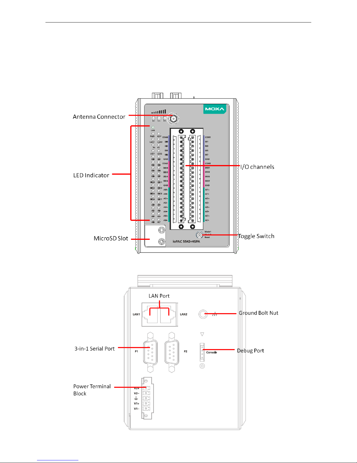
Appearance
The following figures depict ioPAC 5500 RTU controller.
Front View
Top View
Page 8

ioPAC 5500 Hardware Introduction
1-4
Dimensions
Unit: mm (inch)
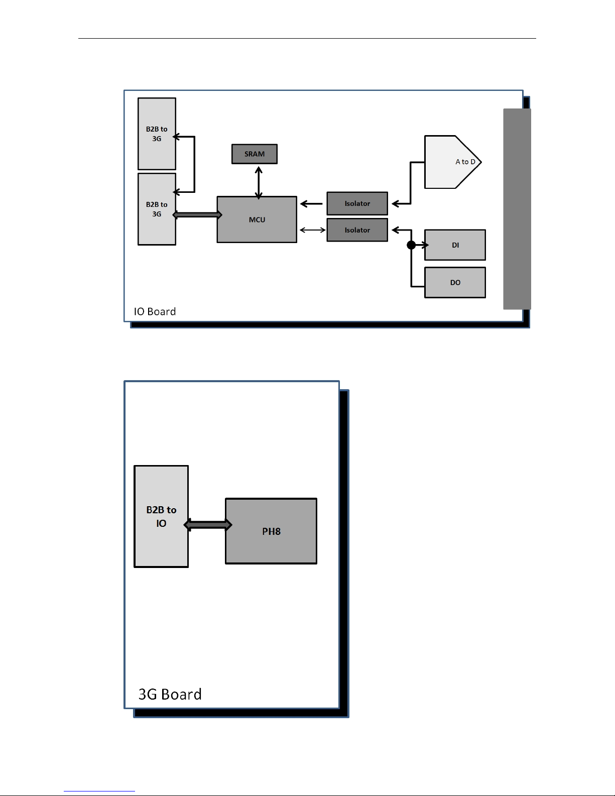
Hardware Block Diagrams
ioPAC 5500 RTU Controller Block Diagram
CPU Board
Page 9
ioPAC 5500 Hardware Introduction
1-5
I/O Board
3G Board
Page 10

ioPAC 5500 Hardware Introduction
1-6
Product Hardware Specifications
Product Selection Guide
Model Name Description
ioPAC 5542-C-T RTU controller, 8AIs, 8 DIs, 8DIOs, C/C++, -40 to 75°C operating
temperature
ioPAC 5542-HSPA-C-T RTU controller with HSPA module, 8AIs, 8 DIs, 8DIOs, C/C++, -30 to 75°C
operating temperature
ioPAC 5542-IEC-T RTU controller, 8AIs, 8 DIs, 8DIOs, IEC 61131-3, -40 to 75°C operating
temperature
ioPAC 5542-HSPA-IEC-T RTU controller with HSPA module, 8AIs, 8 DIs, 8DIOs, IEC 61131-3, -30 to
75°C operating temperature
NOTE
Conformal coating available on reques t.
Product Specifications
Computer
Main CPU:
32-bit ARM9 192 MHz CPU
I/O CPU:
32-bit ARM Cortex M4 80 MHz CPU
OS:
Linux
Clock:
Real-time clock with battery backup
Memory:
•
SDRAM: 64 MB
• Flash: 32 MB
• SRAM: 256 KB (battery backup lasts for 1 week)
• microSD™ Slot: Up to 32 GB (SD 2.0 compatible)
Note: For units operating in extreme temperatures , industrial grade, wide
-temperature microSD cards are
required.
Cellular (for the ioPAC 5542-HSPA Series)
Network:
• Quad
-band GSM/GPRS/EDGE 850/900/1800/1900 MHz
• Five
-band UMTS/ H S P A + 800/850/AWS /1900/2100 MH z
Internet:
HSPA:
• Up to 5.76 Mbps upload speed
• Up to 14.4 Mbps download speed
UMTS: Up to 384 kbps upload/downloa
d speed
EDGE Class 12: Up to 237 kbps upload/download speed
GPPRS Class 12: Up to 85.6 kbps upload/download speed
SMS:
Point-to-Point Text/PDU mode
SIM Control Voltage:
3/1.8 V
Ethernet Interface
LAN:
2 x 10/100 Mbps, 2 MACs (IPs), RJ45
Protection:
1.5 kV magnetic isolation
Serial Communication
Interface:
• 2 RS
-232/422/485 ports, software selectable (DB9 male)
• 1 RS
-232 debug port (4-pin connector)
Serial Line P r ot ec tion:
15 kV ESD for all signals
Page 11

ioPAC 5500 Hardware Introduction
1-7
Serial Communication Para me ters
Parity:
None, Even, Odd
Data Bits:
7, 8
Stop Bits:
1, 2
Flow Control:
RTS/CTS, XON/XOFF
Baudrate:
300 bps to 921. 6 kbps
Serial Signals
RS
-232: TxD, RxD, DTR, DSR, RTS, CTS, DCD, GND, RI
RS
-422: Tx+, Tx-, Rx+, Rx-, GND
RS
-485-4w: Tx+ , Tx-, Rx+, Rx-, GND
RS
-485-2w: Data+, Data-, GND
Inputs and Outputs
Analog Inputs:
8 channels
Digital Inputs:
8 channels
Configurable DIOs:
8 channels
Isolation:
3k VDC or 2k Vrms
Analog Input
Type: Differential Inp ut
Resolution:
16 bits
I/O Mode:
Voltage / Current
Input Range:
0 to 10 VDC, -10 to 10 VDC , 0 to 20 mA , 4 to 20 m A (w i re off)
Historical Data Buf fering:
60KB per channel, 120 second data buffer at 250 Hz
Accuracy:
±0.1% FSR @ 25°C
±0.3% FSR @
-40 and 75°C
Sampling Rate:
• All
channels: 2000 samples/sec
• Per channel: 250 samples/sec
Input Impedance:
2M ohms (min.)
Built
-in Resistor for Current Input: 120 ohms (min.)
Digital Input
Sensor Type:
Wet Contact (NPN or PNP), Dry Contact
I/O Mode:
DI, Counter or Frequency
Dry
Contact:
• On: short to GND
• Off: open
Wet Contact:
NPN (DI to GND):
• On: 0 to 3 VDC
• Off: 10 to 30 VDC
PNP (DI to GND):
• Off: 0 to 3 VDC
• On: 10 to 30 VDC
Common Type:
4 points per COM
Counter Frequency:
1 kHz
Digital Filtering Time Interval:
Software selectable (by 0.5 ms)
Digital Output
Type:
Sink
I/O Mode:
DO or PWM
Pulse Output Freque nc y:
1 kHz
Over
-voltage Protection: 45 VDC
Over
-current Protection: 2.6 A (4 channels @ 650 mA)
Over
-temperature Shutdown: 175°C (typical), 150°C (min.)
Current Rat ing:
200 mA per channel
Page 12

ioPAC 5500 Hardware Introduction
1-8
Software Characteristics
Automation Languages: C/C++, IEC 6 11 31-3
Protocols:
Modbus TCP/RTU (master/slave), SNMP TCP/IP, UDP, DHCP, BOOTP, S NTP, SMTP
Power Requiremen t s
Power
Input:
• ioPAC 5542
-HSPA series: 305 mA @ 24 VDC
• ioPAC 5542 series: 264 mA @ 24 VDC
Physical Characteristics
Housing:
Aluminum
Dimensions:
90.05 x 135 x 105.4 mm (3.55 x 5. 32 x 4.15 in)
Weight:
• ioPAC 5542
-HSPA Series: 1100 g (2.43 lb)
• ioPA C 5542 Series: 1000 g (2.20 l b )
Mounting:
DIN-Rail mounting (standard), wa ll mounting (op tional)
Connector:
Spring-type terminal block
Environmental Limits
Operating Temperature:
• ioPAC 5542 Series :
-40 to 75°C (-40 to 176°F)
• ioPAC 5542
-HSPA Series: -30 to 75°C (-2 2 to 176°F)
Storage Temperature:
-40 to 85°C (-40 to 185°F)
Ambient Relative Humidity:
5 to 95% (non-condensing)
Shock:
IEC 60068-2-27
Vibration:
IEC 60068-2-6
Altitude:
Up to 2000 m
Note: Please contact Moxa if you require products
guaranteed to function properly at higher altitudes.
Standards and Cer tifications
Safety:
UL 508
EM
C: EN 55022/ 24
EMI:
FCC Part 15 Subpart B Class A, CISPR 22
EMS:
IEC 61000
-4-2 ESD: Contact: 4 kV; Air: 8 kV
IEC 61000
-4-3 RS: 80 MHz to 1000 MHz: 3 V/m
IEC 61000
-4-4 EFT: Power: 1 kV; Signal: 0.5 kV
IEC 61000
-4-5 Surge: Power: 2 kV (L-PE), 1 kV (L-L); Signal: 1 kV
IEC 61000
-4-6 CS: 3 V
IEC 61000
-4-8 PFMF: 1 A/m
Radio
: NCC
Rail Traffic:
EN 50121-4
Hazardous Location:
Class 1 Division 2
Note: Please check Moxa’s website for the most up-to-date certification status.
Warranty
Warranty Period:
5 years
Details:
See www.moxa.com/warranty
Page 13

2
2. Installation
This chapter includes instructions on how to insta ll the io PAC 5500.
The following topics are covered in this chapter :
Basic Installation
DIN Rail Installation Procedure
Configuring the Power
Powering on the ioPAC Controller
Grounding the ioPAC
Installing a microSD Card
ioPAC 5500 LED In di c a tor s
System LEDs
Communication LEDs
Cellular
User-Def ined LEDs : LED1 and LED2
IEC-61131-3 Compliant LEDs: R/S and ERR
I/O LEDs
The Toggle S witch
In IEC-61131-3 Models
In C/C++ Models
Toggle Switch: Factory Reset Process
Pin assignment and I/ O wi r ing gui de
Pin As s ignment
Di g ital Input
Di g ital O utp ut
Analog Input
(Voltage)
Analog Input
(Current)
Installing a SIM card
Connecting to the Network
Ethernet Communication
Serial Connectivity
Connecting to a Serial Device
Se rial Console (Debug Port)
Battery
Page 14

ioPAC 5500 Hardware Installation
2-2
Basic Installation
DIN Rail Installation Procedure
Installing the ioPAC 5500 on a DIN Rail
The DIN rail attachment plate should already be fixed to the back panel of the ioPAC 5500 when you take it out
of the box. To install the ioPAC 5500 on a DIN Rail, follow below steps.
NOTE
A wall
mount kit can be purchased separately.
STEP 1:
Insert the top of the DIN
rail into the slot just
below the stiff metal spring
.
STEP 2:
The DIN-rail attachment unit will s nap into
place as shown
to the right.
Removing the ioPAC 5500 from a DIN Rail
To remove the ioLogik unit from the DIN-rail, simply reverse Steps 1 and 2 above.
Page 15

ioPAC 5500 Hardware Installation
2-3
Configuring the Power
Powering on the ioPAC Controller
The ioPAC controller can receive power from a 9 to 48 VDC power. Input power is
applied to the positive (
V1+, V2+) and negative (V1-, V2-) terminals on the
connector.
•
When
the input voltage is below the minimum recommended voltage the ioPAC
will turn off.
•
The ioPAC has reverse protection and power input over-voltage protection,
allowing it to resist a maximum voltage of 60 V, and the ioPAC’s power inp ut
over-current fuse protection specification is 5 A at 25°C.
After connecting the Moxa ioPAC controller to the power supply, it will take 30 to 60 seconds for the operating
system to boot up. The green Ready LED will not turn on until the operating system is ready .
ATTENTION
This product is intended to be supplied by a Listed Power Unit with output marked “LPS” and rated for 9-48 VDC
(minimum requirements). For railway rolling stock applications, these devices must be supplied by a galvanic
i
solated power supply with design based on the EN 50155 standard.
Grounding the ioPAC
For most applications, it is desirable to ground the system by connecting the system’s power supply common
wire to the chassis or panel ground. The negative (–V) side of the DC power input terminal as well as all I/O
point terminals labeled GND are connected to chassis ground.
NOTE
Use 18 AWG wire for the power ground.
We highly recommend co nnecting the gr o und s crew to the power term inal block’s ground.
Page 16

ioPAC 5500 Hardware Installation
2-4
Installing a microSD Card
The ioPAC is equipped with one slot for a microSD card. The card reader slot is located inside the ioPAC device,
so you will need to unscrew and remove the card cover to install your microSD card. When inserting a microSD
card, remember to keep the front edge of the card facing down.
Follow these steps to remove or install a microSD card:
1. Remove the screw holding the card cover in plac e .
2. (a) Insert a microSD card into the microS D card slot, or
(b) Remove the microSD card from the microSD card slot.
3. Fasten back the screw hold ing the c ard cov er in plac e .
Page 17

ioPAC 5500 Hardware Installation
2-5
ioPAC 5500 LED Indicators
There are 9 LEDs on the ioPAC controller.
Category Label Usage
System
PWR System Power On: Power On
Off: Power Off
RDY System (Kernel)
Ready
Green: System Ready
Blinking Green: System is booting up
Red: System error, firmware upgrade, or reset
procedure underway
Blinking Red: Factory res et t rigge re d
C/C++ Version LED1, LED2 User-Defined User-Defined
IEC Version
R/S
Run/Stop Mode Green: The CPU is executing PRDK.
OFF: The CPU has stopped / is not executing PRDK.
ERR
Error Red: System / I/O / services error
OFF: No error (auto update if error fixes)
Communication
LAN1, LAN2 Ethernet
Connection
Green: 100Mb
Amber: 10Mb
Blinking: data transmitting
Off: disconnected
P1, P2 Serial
Connection
Green: Transmitting data (Tx)
Amber: Receivi ng data (Rx )
Off: disconnected
Link Cellular
Connection
Green: ISP/IP retrieved
Off: ISP disconnected
Cellular Signal 1 & 2 & 3: ON (RSSI >= 24)
1 & 2: ON (18 <= RSSI < 24)
1: ON Only (12 <= RSSI < 18)
Off: No Signal (RSSI < 12)
I/O DIn, DIOn Digital Input /
Output Indicator
Green: Channel ON or counter signal in/pulse si g nal
output (scan rate: 1 second)
Off: Channel OFF or No Counter/Pulse Signal
AIn Analog Input
Indicator
Green: Channel Enabled
Red: Burn out & wire off when 4-20 mA current mode
Page 18

ioPAC 5500 Hardware Installation
2-6
System LEDs
PWR (Power LED)
The Power (PWR) LED indicates the status of the system power. When the system is on, this LED will turn green,
and when the system power is off this LED will be off.
RDY (Ready LED)
The Ready (RDY) LED indicates the status of the system’s kernel. When the LED is green the system kernel is
ready. When the LED is green and blinking, the system’s kernel is booting-up. When the Ready (RDY) LED is red,
there is either a system error or the system is being reset to factory defaults. When the Ready LED is red and
blinking, the device’s factory defa ult mod e has been tri ggered .
Communication LEDs
P1 and P2
The ioPAC controller comes with two serial conne c ti o ns . P1 and P2 represe nt the status of eac h serial
connection. When the LED is green, the ioPAC is transmitting data (Tx). When the the LED is amber, the ioPAC
is receiving data (Rx). When the LED is blinking randomly, data is e ither be ing trans mitte d or received. For
example, if P1 is blinking and is green, the ioPAC is transmitting d ata .
When the LED is off, the serial connection is disconnecte d .
LAN1 and LAN2
The ioPAC controller comes with two Ethernet ports, with the LAN1 and LAN2 LEDs used to represent the status
of the two connections. When the LED is green, data is transmitting at 100 Mbps. When the LED is amber, data
is transmitting at 10 Mbps. When the LED is blinking, data is being transmitted. When the LED is off, there is
no Ethernet connection, or the Ethernet connec tio n has been dis conne c te d.
Cellular
The ioPAC 5542-HSPA RTU controller supports a cellular (HSPA) communications. The Link LED can detect the
communication status and the cellular signal c an dete c t the signal strength of the cellular connection.
User-Defined LEDs: LED1 and LED2
The ioPAC controller allows the user to custom configure these two LEDs (through the software interface).
Refer to the C/C++ Sample Code Programming Guide for ioPAC RTU Controllers for details.
IEC-61131-3 Compliant LEDs: R/S and ERR
The ioPAC controller supports IEC-61131-3-compliant Run/Stop and Error (ERR) LEDs for ISaGRAF-specific
notifications. These LEDs are not user conf ig urable.
I/O LEDs
The ioPAC 5542 RTU controller has I/O LED indicators that directly display the status of I/Os on the front panel
of the ioPAC 5542 RTU controller.
Page 19

ioPAC 5500 Hardware Installation
2-7
The Toggle Switch
The toggle switch functions differently depending on the programming langua g e se t your ioPA C mode l is
configured for.
In IEC-61131-3 Models
For IEC-61131-3 models, the toggle switch is a simple run/stop switch for IEC
programs. Users can enable or disable it thro ug h RTUxpr ess. The default
setting is disabled.
In C/C++ Models
On models that use the C language set, the toggle switch is programmable,
giving integrators and end-users a switch that can trigge r on e of two
operation modes (refer to the C/C++ Sample Code Programming Guide
for ioPAC RTU Controllers for details).
Toggle Switch: Factory Reset Process
Use the following procedure to reset the ioPAC to the factory defaults. Note that when you reset the ioPAC, all
of your tag definitions, software programs, and files will be deleted, and the service and runtime engine will be
restarted.
1. When the system is booting up and the RDY LED is blinking GREEN , ho ld the togg le switc h in the “r eset”
position.
2. Continue to hold toggle switch until the “RDY” LED turns a solid RED, and then release the toggle switch. It
will take around 90 seconds to complete the factory reset pro ces s .
3. When the “RDY” LED starts blinking GREEN (indicating that the kernel is rebooting), the factory mode is
completed.
NOTE
Do NOT power off, operate, or connect any devices when the “RDY” LED is a solid RED.
The factory reset
function is only activated when the system is booting up .
Page 20

ioPAC 5500 Hardware Installation
2-8
Pin assignment and I/O wiring guide
The following is the ioPAC 5542 RTU controller’s pin ass ig nment and I/O w iring guid e .
Pin Assignment
Pin Name Description Pin Name Description
1 COM0 COM of DI0, DI2, DI4,
and DI6
2 COM1 COM of DI1, DI3, DI5, and
DI7
3 DI0 Digital Input Channel 0 4 DI1 Digital Input Channel 1
5 DI2 Digital Input Channel 2 6 DI3 Digital Input Channel 3
7 DI4 Digital Input Channel 4 8 DI5 Digital Input Channel 5
9 DI6 Digital Input Channel 6 10 DI7 Digital Input Channel 7
11 GND Ground 12 GND Ground
13 COM2 COM of DIO0, DIO2,
DIO4, and DIO6
14 COM3 COM of DIO1, DIO3, DIO5,
and DIO7
15 DIO0 Digital I nput/O utp ut
Channel 0
16 DIO1 Digital Input/Output
Channel 1
17 DIO2 Digital Input/Output
Channel 2
18 DIO3 Digital Input/Output
Channel 3
19 DIO4 Digital Input/Output
Channel 4
20 DIO5 Digital Input/Output
Channel 5
21 DIO6 Digital I nput/O utp ut
Channel 6
22 DIO7 Digital Input/Output
Channel 7
23 GND Ground 24 GND Ground
25 AI0+ Analog Input Channel 0 + 26 AI1+ Analog Input Channel 1 +
27 AI0- Analog Input Channel 0 - 28 AI1- Analog Input Channel 1 29 AI2+ Analog Input Channel 2 + 30 AI3+ Analog Input Channel 3 +
31 AI2- Analog Input Channel 2 - 32 AI3- Analog Input Channel 3 33 AI4+ Analog Input Channel 4 + 34 AI5+ Analog Input Channel 5 +
35 AI4- Analog Input Channel 4 - 36 AI5- Analog Input Channel 5 37 AI6+ Analog Input Channel 6 + 38 AI7+ Analog Input Channel 7 +
39 AI6- Analog Input Channel 6 - 40 AI7- Analog Input Channel 7 -
Page 21

ioPAC 5500 Hardware Installation
2-9
Digital Input
Digital Output
Analog Input
(Voltage)
Analog Input
(Current)
Page 22

ioPAC 5500 Hardware Installation
2-10
Installing a SIM card
ioPAC 5542-HSPA contro l le r supp or ts cellular network function. user can unscrew and remove the SIM card
cover to insert the SIM card.
Follow these steps to remove or install a SIM card:
1. Remove the screw holding the card cover in place .
2. (a) Insert the SIM card into the slot, or
(b) Remove the SIM card from the slot.
Connecting to the Network
Ethernet Communication
Connections to the LAN port are made through an RJ45 connector on the module. The wiring and pin
connections for these connectors are descr ibe d in separate sections below.
• TCP/IP Settings: Dual Speed Functionality: The ioPAC 5500’s Ethernet ports auto negotiate with the
connected devices and t hen use the fast est data transmission rate supported by both devices. The following
table shows the TCP/IP parameters supported by the LAN port. Default values are set when a Factory Reset
is performed on the controller.
Lan Po rt 1 Lan Po rt 2
Parameter Supported Values Parameter Supported Values
IP Address Default: 192. 168.127.254 IP Address Default: 192.168.126.254
Subnet Mask Default: 255.255.255.0 Subnet Mask Default: 25 5.255.255.0
Gateway Default: 0.0.0.0 Gateway Default: 0.0.0.0
IP Address is the IP address of the controller.
Subnet Mask de te rmine s the sub ne t on which the controller is located.
Gateway determines how your contr o ll er com munic a te s with devices outside its subnet. Enter the IP
address of the gateway.
The IP address, subnet mask, and gateway are static; contact your network administrator to obtain these
addresses for the controller.
RJ45 Ethernet Connector
The ideal maximum cable length of a 10/100BaseT connection is 100 m (350 feet), but the actual limit could be
longer or shorter depending on the amount of electrical noise in the environment. To minimize the amount of
noise, Ethernet cables should not run parallel to power cables or other types of cables that generate electrical
noise.
The following diagram and table shows the pin connec tions for the RJ45 Ethernet connector.
Page 23

ioPAC 5500 Hardware Installation
2-11
RJ45 Connector Pin Assignment
Contact Media Direct Interface Signal
1 Tx + (transmit)
2 Tx - (transmit)
3
Rx + (receive)
4 Not used
5 Not used
6 Rx - (receive)
7 Not used
8 Not used
Port Trunking
The ioPAC 5500 RTU controller has a Port Trunking function (active backup mode) that can convert two
LAN-port IP addresses into one virtual IP address for easy SCADA integration and Ethernet redundancy. In the
following diagram, both LAN ports on each ioPAC RTU controlle r are connected to a managed switch on an
Ethernet network running SCADA software. For more details regarding configuration setup, refer to the ioPAC
RTU Software User’s Manual.
Serial Connectivity
Connecting to a Serial Device
The ioPAC RTU is equipp e d with two 3-in-1 ser ial ports that support RS-232/422/485, making it more
convenient to connect field serial devic e s .
Pin RS
-232
RS
-422 and 4-wire RS-485 2-wire RS-485
1
DCD
TxD-(A)
–
2 RXD TxD+(B)
– 3 TXD RxD+(B)
Data+(B)
4 DTR RxD
-(A)
Data
-(A)
5 GND GND GND 6 DSR – – 7 RTS – – 8 CTS – – 9 RI – –
Page 24

ioPAC 5500 Hardware Installation
2-12
Serial Console (Debug Port)
The serial console gives users a convenient way of connecting to the RTU controllers. This method is
particularly useful when using the computer for the first time. The serial console is also effective for connecting
the Moxa RTU controllers when you do not know target network setting s and IP addre sses.
Step 1: To use the serial console, remove the cover from the front/top panel first.
Console Port for the ioPAC Series
Step 2: Attach the 4-pin serial console cable to the console port. The following diagram shows the 4-pin serial
connector and pin connections.
Pin Assignment for the Serial Console Port
Pin Definition
1
TxD
2 RxD 3 NC 4 GND
Serial Console Default Settings
Parameter Value
Baudrate 115200 bps
Parity None
Data bits 8
Stop bits 1
Flow Control None
Terminal VT100
We recommend using Moxa PComm Terminal Emulator to connect to the serial console. The following steps
describe how to connect the console.
1. Download Moxa PComm Lite from the Moxa website (www.moxa.com
) or copy it from the following folder
on the Documentation and Software CD: Software\utility\PComm\.
2. Install Moxa PComm Lite to the ho s t Windows PC.
3. Run PComm Lite Terminal Emulator from Start Programs PComm Lite Ver 1.x Terminal
Emulator.
4. Click Profile Open.
Page 25

ioPAC 5500 Hardware Installation
2-13
5. Specify which COM port is connecting to the Moxa RTU, and use the following configuration settings:
115200, 8, none, 1.
6. Click on the Terminal tab and configure the Terminal Type to VT100. Click OK to proceed.
7. The serial console will b e di splaye d on the terminal scr e e n.
Battery
The ioPAC RTU controller is equipped with one built-in, rechargeable VL2020 3V battery for the SRAM and one
3V rechargeable battery (model number VL-1220) for the Real Time Clock (RTC).
• Rechargeable battery (VL2020) for SRAM
Sustains at le ast 1 week without power supply
Capacity: 20 mAh
Typical consumption (@ 25°C): 4 μA
5-year warranty
• Rechargeable battery (VL-1220) for RTC
Sustains power for at least 1 week without power supply
Capacity: 7 mAh
Typical consumption (@ 25°C): 2 μA
5-year warranty
Page 26

ioPAC 5500 Hardware Installation
2-14
Caution
Do
NOT attempt to replace the battery. Contact your local dealer for replac e me nt assi s tance.
Page 27

3
3. The RTUxpress Utility
In this chapter, we introduce Moxa’s RTUxpress Utility. The ioPAC Series can be managed and configured over
an Ethernet using RTUxpress, which provide s easy access to all status inf or m ation and ready-to-run service
settings.
The following topics are covered in this chapter :
RTUxpress Introduction
Quick Start
User Interface
Device and Service Configuration
Se ttings Page
Log Message Window
Page 28

ioPAC 5500 Hardware The RTUxpress Utility
3-2
RTUxpress Introduction
Moxa RTUxpress is a user-friendly and intuitive offline configuration tool for configuring Moxa’s ioPAC
Programmable Controllers. RTUxpr e ss is provided free of charge, and can be upgraded for free when future
upgrades become available. RTUxpress has a user-friendly interface for device setup, tag management, and
service configuration.
The TagEasy feature implements tag-centric programming through RTUxpress, in which a “tag” links resources
(DI, DO, AI, etc.) with ready-to-run servic e s (alar ms , log g i ng, active tags, etc.).
For example, users can read a pre-defined DI tag to get the channel status, or change the value of a
pre-defined internal variable to trigger a logging servic e .
From the point of view of the engineer responsible for programming, the focus has changed from incorporating
lots of APIs to just configuring simple tags instead .
This change of focus greatly reduces the programming effort.
Moxa’s ioPAC programmable controllers provide ready-to-run services, including alarms, data lo g ging, and
communication, to help programmers reduce the time and effo rt needed for program design. With Moxa’s
RTUxpress utility, programmers only nee d to configure the appropriate services, and then upload the
configuration file to the ioPAC programmable controllers. Once io PAC is conf igured, all of the services will be
ready to run.
Ready-to-Run Services
Alarms
E-mail SMS
SNMP
Trap
OT Protocol
Modbus
Master
Modbus
Slave
Active
OPC
IT
Protocol
SNMP
RESTful
API
Log
Data
Logging
FTP
Page 29

ioPAC 5500 Hardware The RTUxpress Utility
3-3
Quick Start
When you start RTUxpress, click on New Project, Open Project, or Help, located at the bottom of RTU Quick
Start window. If do not want the Quick Start window to appear the next time you log in, select the Do not
show this Quick Start again checkbox before proceeding .
New Project
When you create a new ioPAC 8600 project for ioPAC 8600 device configuration, you can specify the Project
Name, set the Product Series to ioPAC 8600, and choose the C/C++ or IEC 61131-3 programming language
from the Select Device dropdown box. Click OK to proceed.
Page 30

ioPAC 5500 Hardware The RTUxpress Utility
3-4
The New CPU and Power Modules dialog allows you to specify the characteristics of the backplane module
you are using.
• Select the number of slots from the No. of Slots dropdown box.
Three models are supported: 5 slots, 9 slots, 12 slots.
• Select the CPU model you are using from the CPU module dropdown box.
• Select the model of power module you are using from the Power 1 Module dropdo wn box.
• ioPAC 8600 9-slot and 12-slot backplane modules suppo rt redundant power modules. If you are using
either a 9-slot or 12-slog module, you can select an additional power module from the Power 2 Module
dropdown box.
NOTE
You must specify the same power module models in the Power 1 Module and Power 2 Module dropdown boxes.
Open Project
When you click on the Open Project icon from the Quick Start interface, use the Open dialog to select which
project you would like to open.
Page 31

ioPAC 5500 Hardware The RTUxpress Utility
3-5
Help
Click the Help button to open the RTUxpress help utility, and then sele c t a help top ic from the left me nu.
Exit
Click the Exit icon to close the RTUxpress utility .
Page 32

ioPAC 5500 Hardware The RTUxpress Utility
3-6
User Interface
The RTUxpress interface is divided into six main area s :
• Menu bar
• Tool bar
• Device configuration options
• Service configuratio n options
• Settings panel
• Log message panel
Log Message Window
Device and Service
Configuration
Settings Page
Tool Bar
Menu Bar
Page 33

ioPAC 5500 Hardware The RTUxpress Utility
3-7
Menu Bar
File:
The following options are available und er the File menu item:
• New Project: Create a new RTUxpress project
• Open Project: Open an existing RTUxpress project
• Save Project: Save the RTUxpress projec t that is curr e ntly opened
• Save As: Save the currently opened project as a new project
• Export Configuration to io PAC: Export the configuration file to an ioPAC Programmable Controller
• Import Configuration from ioPA C : Impor t the config uration file from an ioPAC Programmable Controller
• Export Tag Name to C Header File: Export the tag name to a C header file for use in a C/C++ program
• Exit: Close the RTUxpress utility
Tools:
The following options are available und er the Tools menu item:
• Add Module: Add an ioPAC I/O module to the RTUxpress proje c t
• Delete Module: Delete an ioPAC I/O module from the RTUxpres s proje c t
Page 34

ioPAC 5500 Hardware The RTUxpress Utility
3-8
• Change CPU/Power Module: Change the CPU, Power, backplane settings for the RTUxpress project
• Device Information: Get the device infor mation for a particular device
NOTE
A username and
password are required to retrieve device information. the default Username/Password is
moxa/moxa for the ioPAC 8600
-CPU30 series and root/root for other ioPAC series produc ts.
Page 35

ioPAC 5500 Hardware The RTUxpress Utility
3-9
• Time Sync: Synchronize the device time with the PC ’ s time, or set the time manually
• Modify Password: Modify the administr a to r p asswo rd
Page 36

ioPAC 5500 Hardware The RTUxpress Utility
3-10
• Reboot Device: Reboot the ioPAC Progr amm able Co ntro lle r
Page 37

ioPAC 5500 Hardware The RTUxpress Utility
3-11
• Firmware Update: Upgrade the ioPAC Progr am mable Controlle r ’ s fir mware
• Factory Reset: Reset all settings and conf ig urations to default settings
IEC 61131-3 Setting:
a. Resource information: Indicates how many reso urce s are supp orted by the ioPAC and whether or not
the resources are running.
b. ISaGRAF Runtime Engine Reset to Default: Deletes all resources and programs in the ioPAC and restarts
the ISaGRAF runtime engine.
Page 38

ioPAC 5500 Hardware The RTUxpress Utility
3-12
• Online System Log: Users can change the system log settings online .
NOTE
Enabling the log will affect device performance. However, we recommend enabling it so that runtime details will
be logged when the ioPAC
experiences unexpected erro rs.
• Diagnostic & Testing Tool: The tool can be used to pre-test or monitor the IO status of the device. Take the
following steps to use the tool:
Step 1: Start the tool, key in an IP address or auto search for a device, and then then click s ubmit.
Page 39

ioPAC 5500 Hardware The RTUxpress Utility
3-13
Step 2: When the Log in window appears, enter the user name and password to log in. RTUxpress will open
PuTTY to establish an SSH connection between the ioPAC and the PC .
Step 3: When a connection has been established, the slot and API information will be displayed in the PuTTY
window. Use the commands listed on the screen to monitor the device.
NOTE
The tool may affect the operation of the ioPAC. If you want to use the tool when the ioPAC is operating, we
strongly suggest
that you to stop the ioPAC first to avoid unexpected results.
Page 40

ioPAC 5500 Hardware The RTUxpress Utility
3-14
Options:
• Preferences: Allows you to configur e the pr efer e nc es show n below
• Network Interface: Allows you to select the network interface
Help:
• View Help: Opens the RTUxpress.chm help utility
• Moxa ioPAC ISaGRAF Reference Manuals: Ope ns the Moxa_ioPAC_ISaGRAF.chm utility
• About RTUxpress: it will show the RTUxpres s utility version
Page 41

ioPAC 5500 Hardware The RTUxpress Utility
3-15
Tool Bar
New Project: Create a new RTUxpress project
Open Project: Open an existing
RTUxpress project
Save Project: Save a currently opened RTU xp ress project
Add Module: Add an ioPAC I/O module
Delete Module: Delete an ioPAC I/O module
Device Information: Get device informati o n
Time Sync: Device time synchronization
Export Configuration to ioPAC: Expor t a config uration file to the ioPAC Programmable controller
Import Configuration from ioPAC: Imports the configuration file from ioPAC Programmable Controller
Help: Opens the
RTUxpress.chm help utility
Page 42

ioPAC 5500 Hardware The RTUxpress Utility
3-16
Device and Service Configuration
Device Configuration is to configure ioPAC Programmable Controller settings and resources. You can configure
the LAN, IO, an serial settings in the device’s configuration section. Since the product has a modular design, a
module’s function settings will ap pear o nce the module has been added to the devic e .
ioPAC also provides services (Modbus , SNMP, Data Logg i ng , etc.) to red uc e the develop e r’s effort. Configure
the function in the service configuration page, and then upload the configuration to the device. The service will
start working automatically.
Device Configuration
Service Configuraion
Settings Page
Detailed device and configuration setting s will b e displa y ed in this wind ow . Chec k in RTUxp r ess ’ s help f ile for
the definition of each setting.
Log Message Window
Operation and message logs will be displayed in this window for refe renc e .
 Loading...