

Page 1

ioLogik W5300 Series User’s Manual
Ninth Edition, April 2014
www.moxa.com/product
© 2014 Moxa Inc. All rights reserved.
Page 2

ioLogik W5300 User’s Manual
The software described in this manual is furnished under a license agreement and may be used only in accordance with
the terms of that agreement.
Copyright Notice
© 2014 Moxa Inc., All rights reserved.
Trademarks
The MOXA logo is a registered trademark of Moxa Inc.
All other trademarks or registered marks in this manual belong to their respective manufacturers.
Disclaimer
Information in this document is subject to change without notice and does not represent a commitment on the part of
Moxa.
Moxa provides this document as is, without warranty of any kind, either expressed or implied, including, but not limited
to, its particular purpose. Moxa reserves the right to make improvements and/or changes to this manual, or to the
products and/or the programs described in this manual, at any time.
Information provided in this manual is intended to be accurate and reliable. However, Moxa assumes no responsibility for
its use, or for any infringements on the rights of third parties that may result from its use.
This product might include unintentional technical or typographical errors. Changes are periodically made to the
information herein to correct such errors, and these changes are incorporated into new editions of the publication.
Technical Support Contact Information
www.moxa.com/support
Moxa Americas
Toll
-free: 1-888-669-2872
Tel:
+1-714-528-6777
Fax:
+1-714-528-6778
Moxa China (Shanghai office)
Toll
-free: 800-820-5036
Tel:
+86-21-5258-9955
Fax:
+86-21-5258-5505
Moxa Europe
Tel:
+49-89-3 70 03 99-0
Fax:
+49-89-3 70 03 99-99
Moxa Asia
-Pacific
Tel:
+886-2-8919-1230
Fax:
+886-2-8919-1231
Moxa India
Tel:
+91-80-4172-9088
Fax:
+91-80-4132-1045
Page 3

Table of Contents
1. Introduction ...................................................................................................................................... 1-1
Architecture ....................................................................................................................................... 1-2
Using Active OPC Server to Resolve Dynamic IP Addresses ............................................................... 1-2
Resolving Dynamic/Private IP Issues with DDNS.............................................................................. 1-3
Overview ........................................................................................................................................... 1-4
Product Features ................................................................................................................................ 1-4
Appearance ........................................................................................................................................ 1-4
Package Checklist ............................................................................................................................... 1-5
Product Selection Guide ....................................................................................................................... 1-6
Product Specifications ......................................................................................................................... 1-6
Common Specifications ................................................................................................................ 1-6
ioLogik W5312/W5312-T Specifications .......................................................................................... 1-7
ioLogik W5340/W5340-T/W5340-HSPA/W5340-HSPA-T .................................................................... 1-8
2. Getting Started.................................................................................................................................. 2-1
Before Testing .................................................................................................................................... 2-2
Installing the ioAdmin Utility ................................................................................................................ 2-2
Laboratory Testing .............................................................................................................................. 2-3
Grounding the Unit ...................................................................................................................... 2-3
Connecting to a Power Source ....................................................................................................... 2-3
Connecting to ioAdmin via Ethernet ...................................................................................................... 2-3
Configuring the Computer’s IP Address .......................................................................................... 2-3
Activating ioAdmin and connecting to the ioLogik ............................................................................ 2-4
Configuring Digital I/O Channels ........................................................................................................... 2-6
Connecting I/O Devices ................................................................................................................ 2-7
Testing I/O Devices ..................................................................................................................... 2-8
DIN Rail / Wall Mounting .............................................................................................................. 2-9
Installing/Removing SIM and SD Cards .......................................................................................... 2-9
Connecting the ioLogik W5300 to a Cellular Network...................................................................... 2-10
Installing AOPC on a Host with a Static IP Address ........................................................................ 2-11
Import/Export a Configuration File ...................................................................................................... 2-12
Using ioAdmin to Import/Export a Device Configuration ................................................................. 2-12
3. The ioAdmin Utility ............................................................................................................................ 3-1
System Requirements ......................................................................................................................... 3-2
Key Features ............................................................................................................................... 3-2
Using the ioAdmin Utility ..................................................................................................................... 3-3
The ioAdmin Utility Window .......................................................................................................... 3-3
ioAdmin Menu Bar ....................................................................................................................... 3-3
The Wiring Guide ......................................................................................................................... 3-6
ioAdmin Quick-Link Buttons .......................................................................................................... 3-7
ioAdmin Navigation Panel .................................................................................................................... 3-7
Main Window .............................................................................................................................. 3-9
Synchronization Rate Status Bar ................................................................................................. 3-10
ioAdmin Status Bar .................................................................................................................... 3-10
ioAdmin Configuration Panels ............................................................................................................. 3-11
The Server Settings Panel .................................................................................................................. 3-11
The LAN Settings Panel ..................................................................................................................... 3-12
The I/O Configuration Panel ............................................................................................................... 3-13
Configuring AI Channels ............................................................................................................. 3-13
Configuring Digital I/O Channels ................................................................................................. 3-15
Configuring Digital Input Channels .............................................................................................. 3-16
Configuring Digital Output / Relay Output Channels ....................................................................... 3-18
Testing DI and DO Channels ....................................................................................................... 3-19
The I/O Expansion Panel .................................................................................................................... 3-20
I/O Expansion: Step-by-Step ...................................................................................................... 3-21
The Active Tags Panel ....................................................................................................................... 3-23
Active OPC: Redundancy Mode .................................................................................................... 3-23
The Cellular Settings Panel................................................................................................................. 3-26
Dial-up Setting .......................................................................................................................... 3-26
Caller IDs ................................................................................................................................. 3-26
Operation Mode ......................................................................................................................... 3-27
DDNS Settings .......................................................................................................................... 3-27
VPN Settings Panel (ioLogik W5340-HSPA(-T) only) ....................................................................... 3-28
VPN System Log Events and Error Codes ...................................................................................... 3-32
Cellular Reconnection ................................................................................................................. 3-33
Meter/Sensor ............................................................................................................................ 3-34
Network Statistics ..................................................................................................................... 3-35
Watchdog Panel ........................................................................................................................ 3-35
Click&Go Logic Panel .................................................................................................................. 3-36
Page 4

4. Click&Go Logic .................................................................................................................................. 4-1
To Get a Quick Start… ......................................................................................................................... 4-2
Overview ........................................................................................................................................... 4-2
Features ..................................................................................................................................... 4-3
Click&Go Logic Basics .................................................................................................................. 4-3
Working with the Rules ................................................................................................................ 4-4
Click&Go Development Process ............................................................................................................. 4-4
I/O Configuration ................................................................................................................................ 4-4
Configurable DIO Channel Mode Selection ...................................................................................... 4-4
Digital Input Mode Selection ......................................................................................................... 4-5
Digital Output Mode Selection ....................................................................................................... 4-6
Analog Input Mode Selection ......................................................................................................... 4-6
Alias Configuration ...................................................................................................................... 4-7
Testing the I/O Channels .............................................................................................................. 4-7
Defining Global Variables ..................................................................................................................... 4-8
Internal Register (Integer) Settings ............................................................................................... 4-8
Timer Settings ............................................................................................................................ 4-8
SN M P Tr a p Server........................................................................................................................ 4-9
E-Mail Server .............................................................................................................................. 4-9
Active Message Server ............................................................................................................... 4-10
SMS Phone Book ....................................................................................................................... 4-10
Working/Off Working Days .......................................................................................................... 4-11
FTP Settings ............................................................................................................................. 4-11
Data Logging Profile List ............................................................................................................. 4-12
Internal Register (Float) Settings................................................................................................. 4-14
Working with Logic ........................................................................................................................... 4-15
Click&Go Logic Basics ................................................................................................................ 4-15
IF…THEN/ELSE Conditionals ........................................................................................................ 4-17
THEN/ELSE Actions .................................................................................................................... 4-23
Activating the Rule-set ...................................................................................................................... 4-30
Upload, Restart, and Run ........................................................................................................... 4-30
Rule-set Management Bar .......................................................................................................... 4-31
Import/Export Configuration .............................................................................................................. 4-31
5. Planning and Assistance.................................................................................................................... 5-1
Known Issues of Cellular Monitoring Systems ......................................................................................... 5-2
Active OPC Server with a Static IP Address ............................................................................................ 5-3
Cellular Remote I/O Architecture .......................................................................................................... 5-4
Using ioAdmin to Perform Simple Data Monitoring from a Remote Site ...................................................... 5-4
Expanding Input/Output Channels ........................................................................................................ 5-6
Using Modbus/TCP Protocol with Your Program ....................................................................................... 5-8
Using the Counter to Get Meter Readings and Statistics ......................................................................... 5-10
Record your I/O Data in the Data Log File ............................................................................................ 5-11
Connecting a Modbus/RTU Serial Device Attached to the ioLogik over a Cellular Network ........................... 5-18
Connecting to a SCADA System .......................................................................................................... 5-18
Updating Serial Tags to SCADA System with Active OPC Server over a Cellular Network ............................ 5-20
Handling Front-End Events and Alarms ................................................................................................ 5-21
SMS Escalation and Acknowledgement ................................................................................................ 5-22
SMS Commands for Monitoring and Control ......................................................................................... 5-25
Enabling the Power Saving Function and Secure Wake on Call ................................................................ 5-26
Enabling Ethernet and Cellular Redundancy.......................................................................................... 5-26
A. Pin-outs and Cable Wiring ................................................................................................................. A-1
Pinouts .............................................................................................................................................. A-2
CN1: SMA, Cellular Antenna Connector .......................................................................................... A-2
CN2: DB9, Male, RS-232 Connector ............................................................................................... A-2
CN3: RJ-45, Ethernet Connector.................................................................................................... A-2
TB1: Power Input Terminal Block ................................................................................................... A-3
TB2: I/O Terminal Block (W5340) .................................................................................................. A-3
TB3: 5-pin, 4-wire/2-wire RS-422/485 Terminal Block...................................................................... A-3
TB2: I/O Terminal Block (W5312) .................................................................................................. A-4
Cable Wiring ...................................................................................................................................... A-4
Digital Input Dry Contact .............................................................................................................. A-4
Digital Input Wet Contact ............................................................................................................. A-4
Digital Output Sink Mode .............................................................................................................. A-5
Relay Output .............................................................................................................................. A-5
Analog Input ............................................................................................................................... A-5
B. SMS Commands ................................................................................................................................. B-1
SMS Command Syntax: ....................................................................................................................... B-2
SMS Command Table .......................................................................................................................... B-2
C. Modbus/TCP Address Mapping .......................................................................................................... C-1
ioLogik W5340 and ioLogik W5340-HSPA Modbus Mapping....................................................................... C-2
Page 5

0xxxx Read/Write Coils (support functions 1, 5, 15) ........................................................................ C-2
1xxxx Read only Coils (supports function 2) ................................................................................... C-6
3xxxx Read-only Registers (supports function 4) ............................................................................. C-7
4xxxx Read/Write Registers (supports functions 3, 6, 16) ................................................................. C-8
5xxxx Write Registers (supports function 8) .................................................................................. C-18
ioLogik W5312 Modbus Mapping ......................................................................................................... C-19
0xxxx Read/Write Coils (supports functions 1, 5, 15) ..................................................................... C-19
1xxxx Read only Coils (supports function 2) ................................................................................. C-24
3xxxx Read only Registers (supports function 4) ........................................................................... C-24
4xxxx Read/Write Registers (supports functions 3, 6, 16) ............................................................... C-26
5xxxx Write Registers (supports function 8) .................................................................................. C-38
D. SNMP Agents with MIB II, RS-232-like Groups ................................................................................. D-1
E. Factory Default Settings .................................................................................................................... E-1
F. Troubleshooting the Cellular I/O Connection .................................................................................... F-1
G. FAQ ................................................................................................................................................... G-1
Page 6

1
1. Introduction
Moxa’s ioLogik W5300 series of programmable remote I/O solutions are stand-alone devices with full cellular
communications designed for remote monitoring applications. Using Moxa’s patented Active OPC Server with
push communications technology, ioLogik W5300 economically solve the problem with identification and
addressing that remote, private networks carried over cellular communications typically have with dynamic IP
addresses.
NOTE
Throughout this
user's manual, we use ioLogik W5300 to refer to one of any of the product models in the
ioLogik W
5300 series.
The following topics are covered in this chapter:
Architecture
Using Active OPC Server to Resolve Dynamic IP Addresses
Resolving Dynamic/Private IP Issues with DDNS
Overview
Product Features
Appearance
Package Checklist
Product Selection Guide
Product Specifications
Common Specifications
ioLogik W5312/W5312-T Specifications
ioLogik W5340/W5340-T/W5340-HSPA/W5340-HSPA-T
Page 7
ioLogik W5300 Introduction
1-2
Architecture
Cellular networks usually run in a dynamic IP environment with private IP addresses assigned by the cellular
service provider. To allow private networks to get around the connectivity issues raised by edge devices
configured with dynamically assigned private IP addresses, typically operators purchase high-cost static IP
addresses for each device, with IPs provided by a DDNS or VPN service purchased from an MVNO (Mobile
Virtual Network Operator). Even with DDNS technology, SCADA systems need to assign resources to manage
the DDNS servers. As an alternative, Moxa’s Cellular remote I/O devices use Moxa’s proprietary “push”
technology, called Active OPC Server. With Moxa’s powerful Active OPC Server support, communications
efficiency between ioLogik W5300 devices and the central SCADA are substantially improved. Moxa’s Active
OPC Server’s non-polling communications architecture supports the standard OPC protocol, but instead of
requiring the SCADA to poll edge devices it allows edge devices to actively push communications to the central
HMI/SCADA system, empowering the network with real time I/O updates while substantially cutting network
overhead.
Unlike the requirements of a traditional OPC server (where remote I/O devices must use a static IP so they may
be successfully polled), Active OPC Server and ioLogik products allow engineers the flexibility of configuring
edge devices with dynamic IP addresses. Even when using DHCP addressing, ioLogik devices can push
messages back to the OPC server, allowing wide area I/O networks using dynamic IP cellular accounts. Using
traditional polling OPC applications, I/O devices cannot make use of this approach.
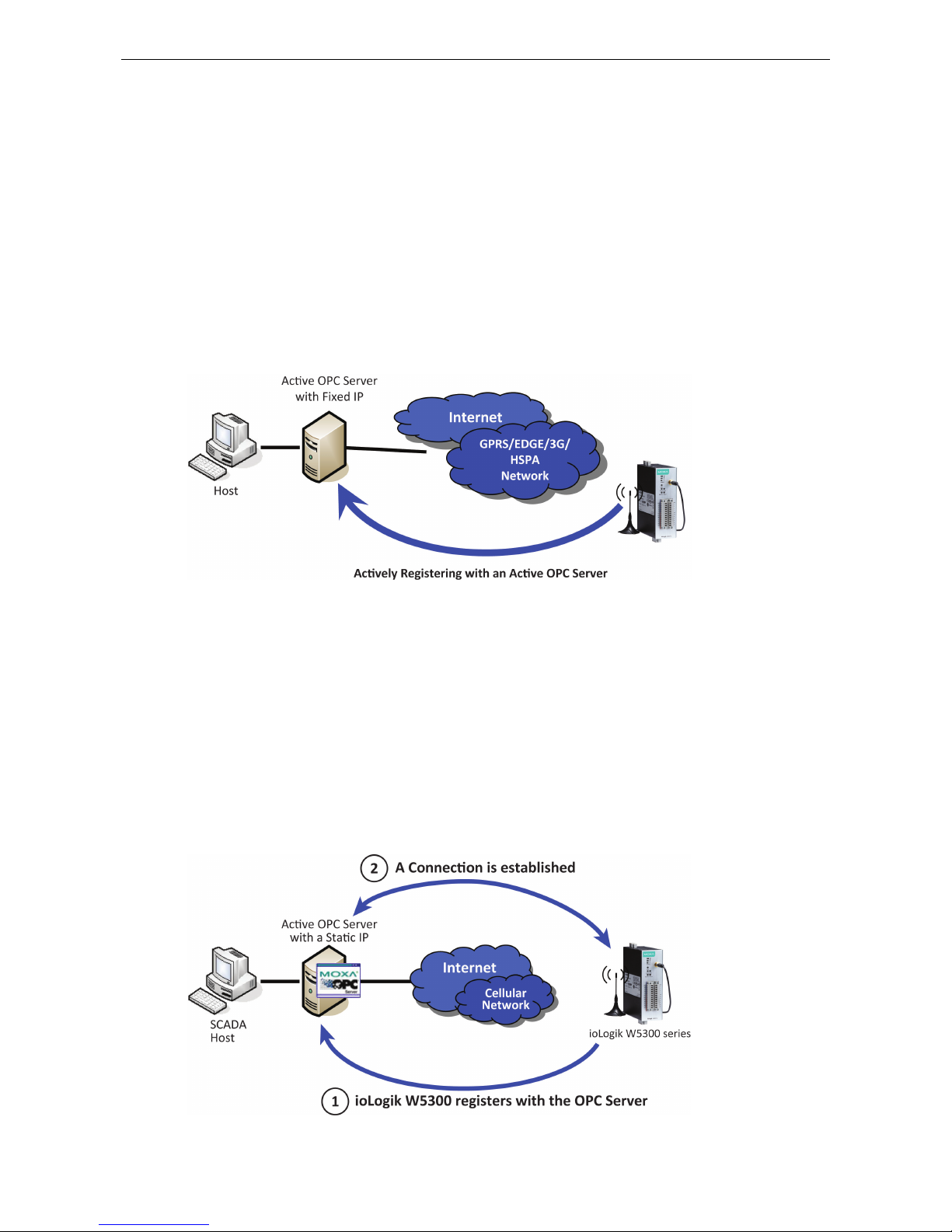
Using Active OPC Server to Resolve Dynamic IP Addresses
With its push communications capabilities, Active OPC Server can be configured to become a cellular gateway
that enables direct communications from the edge back to the core. By configuring the Active OPC Server with
a static address, remote I/O devices may push their IP addresses back to the OPC server and thus register with
the SCADA over a cellular network. In this way, edge devices can communicate their new IP address directly,
easily sidestepping dynamic IP addressing issues. The topology is illustrated below:
Page 8

ioLogik W5300 Introduction
1-3
Each time it reassocaites with a cellular network, an edge device will most likely receive a new IP address from
the carrier. Each time it reassociates, regardless of whether the ioLogik device uses a public IP or private IP, it
will automatically register with the Active OPC Server (which has a static IP address). After registering, the
entire network can be managed by one centralized AOPC server. Thereafter, all I/O data can be read or written
via one powerful cellular device gateway.
The ioLogik W5300 allows you to use a variety of methods to connect with your application software, including
Modbus, OPC client/server, and SNMP. You can also configure AOPC server to send alarms by TCP/UDP, SMS,
and email. For example, if you are using a SCADA application to monitor your system, you can use the OPC
client/server architecture.
Active OPC Server and ioLogik W5300 series products also automatically generate tags, to eliminate the
headache of specifying individual IP addresses, I/O channels, and data formats one by one, or of editing and
importing configuration text files. Instead, Active OPC Server automatically creates the tags for a target ioLogik.
All you need to do is select the channels to be updated from the Active OPC Server. Generally speaking, tag
generation is 50 times faster on Active OPC Server compared to a traditional OPC server, making extra training
for installation and configuration of the OPC no longer a requirement.
The traditional polling architecture occupies more network bandwidth, which results in longer response times.
In comparison, cellular-enabled ioLogik units use push communications, and can report active messages
when predefined events occur. This event-driven logic successfully speeds up I/O response times, allows for
more precise I/O access, and relieves network bandwidth and CPU loading burdens.
Resolving Dynamic/Private IP Issues with DDNS
In addition to using Active OPC Server to register an ioLogik W5300 with SCADA over a dynamic IP cellular
connection, you may also use DDNS to configure the device with a unique URL. The ioLogik W5300 can be
configured to register a DNS hostname (i.e. – URL) with DDNS, and thereby convert a dynamic IP to a
publicized address. In this way, centralized control software will be able to connect to the remote ioLogik
W5300 without requiring a fixed IP or VPN service from a network provider.
NOTE
Device features are dependent on the firmware version. Be sure to use firmware version V1.3 or above for the
ioLogik W5312 series, and V1.5 or above for the ioLogik W5340 series.
Page 9

ioLogik W5300 Introduction
1-4
Overview
The ioLogik W5300 combines a cellular modem, a data logger, and a remote I/O device into one compact
box, dramatically reducing the amount of effort required to integrate devices from multiple vendors. The
cellular interface supports tri-band HSPA/UMTS and quad-band GSM/GPRS/EDGE frequencies, offering a full
spectrum of 3G mobile communication services. The cellular remote I/O unit provides I/O and serial data
logging onto an SD card that can support up to 32 GB of storage space. Multiple options are available to
remotely retrieve data logs, such as FTP, e-mail, and Moxa’s DA-Center™. In addition, this cellular remote I/O
unit is a programmable device that supports Click&Go™ control logic for constructing customized control
systems. The ioLogik W5300 is a rugged device with tolerance for a wide range of temperatures, well suited for
hard-to-wire remote monitoring and alarm applications such at unmanned sites like riversides and pipelines.
Product Features
• Trouble-free connections to cellular networks
• Automatic data update from SD cards following network failure
• Front-end intelligence for event handling
• Intelligent SMS alarms and SMS commands
• Friendly serial device connectivity
• Network redundancy
• WAN-to-LAN extension with port forwarding
• Secure wake on call
• I/O expansion capability
Appearance
NOTE
The reset button restarts the server and resets all settings to factory defaults. Use a pointed object such as
a straightened paper clip to hold the reset button down for 5 sec. The RDY LED will turn red as you are holding
the reset button down. The factory defaults will be loaded once the RDY LED turns green again. You can then
release the reset button.
Page 10
ioLogik W5300 Introduction
1-5
LED Indicators
Function Description Mark
Power Input OFF: No Power PWR
Green: Power On
Connection Status OFF: Disconnected or in “On Demand” Mode GPRS or LINK
Amber: Connected and “Always ON”
Blinking: Connected with Active OPC Server
System Status Green: System Ready READY
Ready LED is blinking and Fault LED is not lit: Click&Go is
running
Ready LED is blinking and Fault LED is blinking: Safe Mode
Communication Activity
(ioLogik W5312,
ioLogik W5340 only)
OFF: No communication DATA
Green: Cellular modular sending/receiving serial TX/RX
command signal
System Fault Status RED: I/O out of work FAULT
OFF: Function Normal
Blinking: Safe Mode
Signal Status OFF: No signal, or No SIM Card SIGNAL
1 Green LED: Weak or insufficient (SMS only)
2 Green LEDs: Average (good for cellular connections)
3 Green LEDs: Excellent Signal
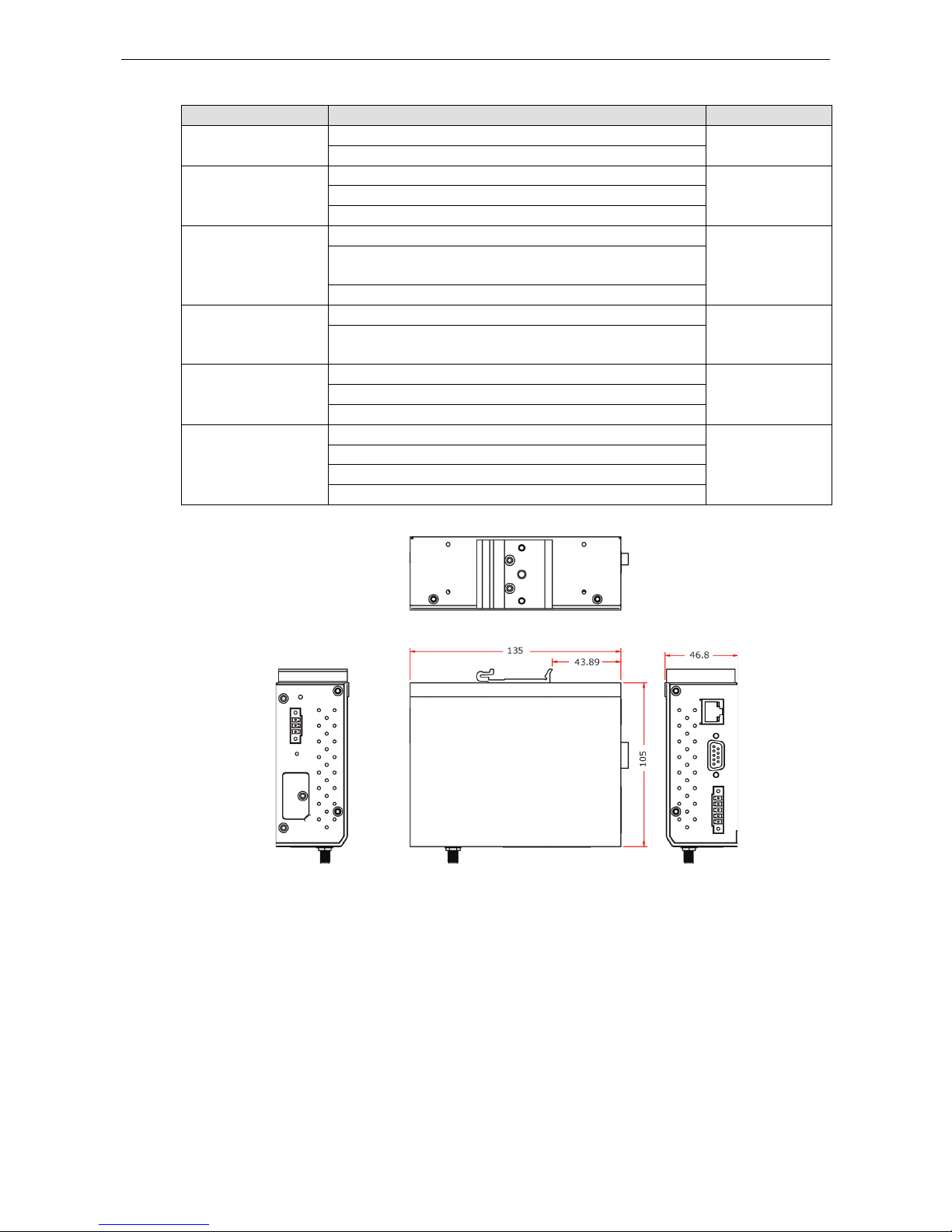
Physical Dimensions (unit = mm)
Package Checklist
The ioLogik W5300 is shipped with the following items:
Standard Accessories
• ioLogik W5300
• 3-pin screw terminal block x 1 (for power input)
• 12-pin screw terminal blocks x 2 (for I/O)
• 5-pin screw terminal block x 1 (for RS-485)
• Installation CD
• Antenna
NOTE: Notify your sales representative if any of the above items are missing or damaged.
Page 11

ioLogik W5300 Introduction
1-6
Product Selection Guide
The cellular-ennabled ioLogik W5300 series of remote I/O units includes the ioLogik W5312, ioLogik W5340,
and ioLogik W5340-HSPA. Their respective features are broken down in the following table:
Model
Operating
Temp.
I/O Combination
Serial
Ports
Ethernet
Ports
Data Logger
OPC
Server
AI
DI
DO
DIO
Relay
W5300 Series Common Specification
W5312 -10 to 55°C 0 8 8 4 0
1, RS-232/
422/485
1, RJ45
Yes, with an
additional SD
card
Yes
W5340 -10 to 55°C 4 0 0 8 2
W5340-HSPA -10 to 55°C 4 0 0 8 2
W5312-T -30 to 70°C 0 8 8 4 0
W5340-T -30 to 70°C 4 0 0 8 2
W5340-HSPA-T -20 to 70°C 4 0 0 8 2
Note: Click on a model name to see specifications relevant to that particular model.
Product Specifications
Common Specifications
Computer
CPU:
ARM9 based CPU, 32-bit/160 MHz
SDRAM/Flash:
• ioLogik W5312: 4 MB
• ioLogik W5340: 2 MB
Storage
Expansion Slot:
Up to 32 GB SD™ memory card (SD 2.0 compatible)
Note: For units operating in extreme temperatures, industrial grade, wide
-temperature SD cards are required.
Cellular
Network:
ioLogik W5312/W5340: Quad
-band GSM/GPRS/EDGE 850/900/1800/1900 MHz
ioLogik
W5340-HSPA: Five band UMTS/HSPA+ 800/850/AWS/1900/2100 MHz
Internet:
HSPA+:
• Up to 5.76 Mbps upload speed.
• Up to 14.4 Mbps download speed.
UMTS:
• Up to 384k bps upload/download speed.
GPRS/EDGE:
• Multi
-slot class: Class 12
• Coding schemes: CS1 to CS
4
• Terminal device class: Class B
SMS:
Point-to-Point Text/PDU mode
SIM Control Voltage:
3 V / 1.8 V
LAN
Ethernet:
1 x 10/100 Mbps, RJ45
Protection:
1.5 kV magnetic isolation
Protocols:
Modbus/TCP, TCP/IP, UDP, DHCP, Bootp, SNMP, SNTP
Serial Communication
Interface:
1 x RS-232/422/485, software selectable
(9-pin D-Sub male, or 5-contact terminal block)
Page 12

ioLogik W5300 Introduction
1-7
Baudrate:
300, 1200, 2400, 4800, 9600, 19200, 38400, 57600, 115200 bps
Power Requirements
Power Input:
24 VDC nominal, 12 to 36 VDC
Physical Characteristics
Dimensions:
46.8 x 135 x 105 mm (1.84 x 5.31 x 4.13 in)
Weight:
495 g
Mounting:
DIN-rail (standard), wall (optional)
Environmental Limits
Operating Temperature:
Standard Models:
-10 to 55°C (14 to 131°F)
Wide Temp. Models:
-30 to 70°C (-22 to 158°F)
Storage Temperature: -40 to 85°C (-40 to 185°F)
Ambient Relative Humidity:
5 to 95% (non-condensing)
Altitude:
Up to 2000 m
Note: Please contact Moxa if you require products guaranteed to function properly at higher
altitudes.
Standards and Certifications
Safety:
UL 508, EN 60950-1, NCC
EMI:
EN 55022; EN 61000
-3-2; EN 61000-3-3;
FCC Part 15, Subpart B, Class A
EMS:
EN 55024, EN 61000-4-2, EN 61000-4-3,
EN 61000
-4-4, EN 61000-4-5, EN 61000-4-6,
EN 61000
-4-8, EN 61000-4-11, EN 61000-6-2
Shock:
IEC 60068-2-27
Freefall:
IEC 60068-2-32
Vibration:
IEC 60068-2-6
Green Product:
RoHS, CRoHS, WEEE
Note: Please check Moxa’s website for the most up
-to-date certification status.
Warranty
Warranty Period:
• ioLogik
W5312: 5 years
• ioLogik W5340/W5340-HSPA: 2 years*
*Because of the limited lifetime of power relays, products that use that component are covered by
a 2
-year warranty.
Details:
See www.moxa.com/warranty
ioLogik W5312/W5312-T Specifications
Inputs and O
utputs
Digital Inputs:
8 channels
Digital Outputs:
8 channels
Configurable DIOs:
4 channels
Isolation: 3K VDC or 2K Vrms
Digital Input
Sensor Type:
Wet Contact (NPN or PNP) and Dry Contact
I/O Mode:
DI or Event Counter
Dry Contact:
• On: short to
GND
• Off: open
Page 13

ioLogik W5300 Introduction
1-8
Wet Contact (DI to GND):
• On: 0 to 3 VDC
• Off: 10 to 30 VDC
Common Type:
6 points per COM
Counter Frequency:
900 Hz, power off storage
Digital Filtering Time Interval:
Software selectable
Digital Output
Type:
Sink
I/O Mode:
DO or Pulse Output
Pulse Output Frequency:
1 kHz
Over
-voltage Protection: 45 VDC
Over
-current Protection: 2.6 A (4 channels @ 650 mA)
Over
-temperature Shutdown: 160°C (min.)
Current Rating:
200 mA per channel
DIO Output Leakage Current:
3.6 mA @ 24 VDC
Power Requirements
Power Consumption:
• Always on: 156 mA @ 24 VDC
• On demand: 138 mA @ 24 VDC
MTBF (mean time between failure)
Time:
407,406 hrs
Database:
Telcordia (Bellcore)
ioLogik W5340/W5340-T/W5340-HSPA/W5340-HSPA-T
Inputs and Outputs
Analog Inputs:
4 channels
Configurable DIOs:
8 channels
Relay Outputs: 2 channels
Isolation:
3K VDC or 2K Vrms
Analog Input
Type:
Differential input
Resolution:
16 bits
I/O Mode:
Voltage / Current
Input Range:
0 to 10 V, ±10 V, ±5 V, 0 to 20 mA, 4 to 20 mA
Accuracy:
• ±0.1% FSR @ 25°C
• ±0.3% FSR @
-30 and 70°C
Sampling Rate:
• All channels: 25 samples/sec
• Per channel: 6.25 samples/sec
• Only one channel enabled: 100 samples/sec
Input Impedance:
200K ohms (min.)
Built
-in Resistor for Current Input: 102 ohms
Digital Input
Sensor Type:
Wet Contact (NPN or PNP) and Dry Contact
I/O Mode: DI or Event Counter
Dry Contact:
• On: short to GND
• Off: open
Wet Contact (DI to GND):
• On: 0 to 3 VDC
• Off: 10
to 30 VDC
Common Type:
4 points per COM
Page 14

ioLogik W5300 Introduction
1-9
Counter Frequency:
900 Hz, power off storage
Digital Filtering Time Interval:
Software selectable/Programmable
Digital Output
Type:
Sink
I/O Mode:
DO or Pulse Output
Pulse Output Frequency:
1 kHz
Over-voltage Protection: 45 VDC
Over
-current Protection: 2.6 A (4 channels @ 650 mA)
Over
-temperature Shutdown: 160°C (min.)
Current Rating:
200 mA per channel
DIO Output Leakage Current:
3.6 mA @ 24 VDC
Relay Output
Type:
Form A (N.O.) power relay
Contact Current Rating:
• Resistive Load: 1 A @ 30 VDC, 250 VAC, 110 VAC
Initial Insulation Resistance:
1000 m ohms (min.) @ 500 VDC
Mechanical endurance:
5,000,000 operations
Electrical endurance:
600,000 operations @ 1 A resistive load
Contact
Resistance: 100 m ohms (max.)
Pulse Output:
0.3 Hz at rated load
Power Requirements
Power Consumption:
ioLogik W5340:
• Always on: 195 mA @ 24 VDC
• On demand: 178 mA @ 24 VDC
ioLogik W5340
-HSPA:
• Always on: 196 mA @ 24 VDC
• On demand: 189 mA @ 24 VDC
MTBF (mean time between failure)
Time:
ioLogik W5340: 196,561 hrs
ioLogik W5340
-HSPA: 280,739 hrs
Database:
Telcordia (Bellcore)
Page 15

2
2. Getting Started
This chapter describes how to install the ioLogik W5300.
The following topics are covered in this chapter:
Before Testing
Installing the ioAdmin Utility
Laboratory Testing
Grounding the Unit
Connecting to a Power Source
Connecting to ioAdmin via Ethernet
Configuring the Computer’s IP Address
Activating ioAdmin and connecting to the ioLogik
Configuring Digital I/O Channels
Connecting I/O Devices
Testing I/O Devices
DIN Rail / Wall Mounting
Installing/Removing SIM and SD Cards
Connecting the ioLogik W5300 to a Cellular Network
Installing AOPC on a Host with a Static IP Address
Import/Export a Configuration File
Using ioAdmin to Import/Export a Device Configuration
Page 16
ioLogik W5300 Getting Started
2-2
Before Testing
Prepare the following items before testing the ioLogik W5300.
1. Set up the Active OPC server environment, including network settings.
2. Install ioAdmin on the same PC serving Active OPC.
Installing the ioAdmin Utility
ioAdmin is a Windows utility provided for the configuration and management of the ioLogik W5300. ioAdmin
can be used from anywhere on the network to monitor and configure the ioLogik W5300.
Installing from the CD: Insert the Document and Software CD into the host computer. In the
Software/Utility directory of the CD, locate and run SETUP.EXE. The installation program will guide you
through the installation process and install the ioAdmin utility. After the installation is finished, run ioAdmin
from the Windows Start menu.
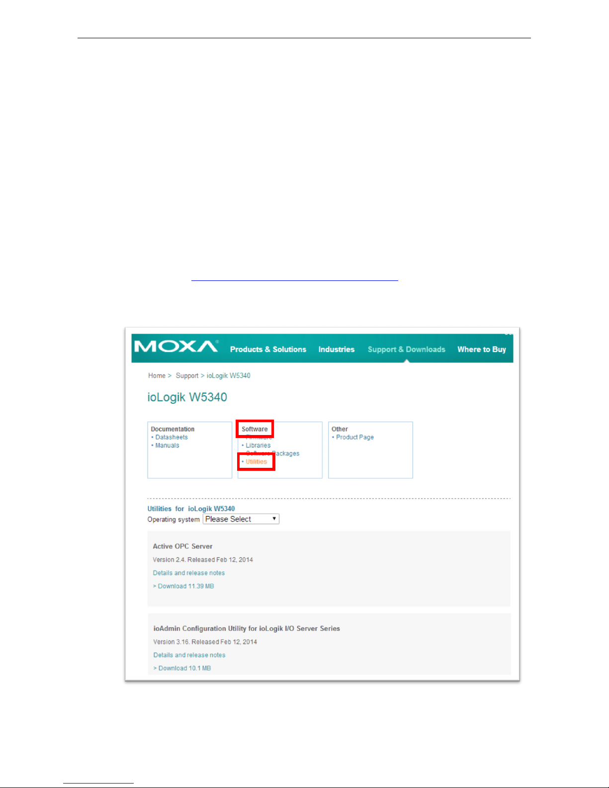
You can also download ioAdmin from Moxa’s website. Navigate to the moxa website at:
http://www.moxa.com/support/search.aspx?type=soft
Once there, enter the name of the product you have purchased into the search bar or select it from the
dropdown menu, and after navigating to the product page click on Utilities, in the middle of the page, located
in the box titled Software.
Page 17
ioLogik W5300 Getting Started
2-3
Laboratory Testing
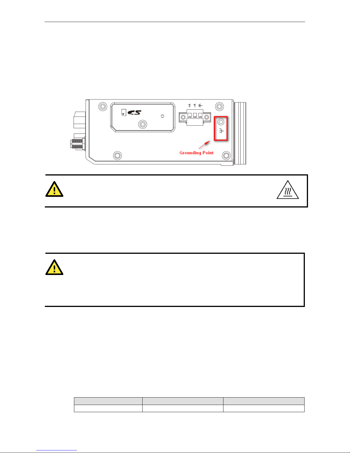
Grounding the Unit
The ioLogik is equipped with one grounding point located on the top of the device next to the Power Input
Terminal Block. To provide better stability for both power and signal transmission, we recommend wiring the
grounding point to a suitable grounded contact, such as the power supply or a cabinet enclosure.
WARNING
This equipment is intended to be used in Restrict
ed Access Locations
. External metal parts are
hot! Before touching it, special attention or protection is necessary.
Connecting to a Power Source
Connect the 12 to 36 VDC power line to the ioLogik’s Power Input Terminal Block. If power is properly supplied,
the PWR LED will glow a steady GREEN color; the READY LED will glow a steady GREEN when the system is
ready.
ATTENTION
Determine the maximum possible current for each power wire and common wire. Observe all electrical codes
dictating the maximum current allowable for each wire size. If the current exceeds the maximum rating, the
wiring could overheat,
causing serious damage to your equipment. For safety reasons, we recommend an
average cable size of 22 AWG. However, depending on the current load, you may want to adjust your cable
size (the maximum wire size for power connectors is 2 mm).
Connecting to ioAdmin via Ethernet
Configuring the Computer’s IP Address
1. For initial configuration, we recommend using a direct connection through the RJ45 Ethernet
console port to a host computer, rather than remotely over the cellular network. Connect the ioLogik to
the host PC with an Ethernet cable.
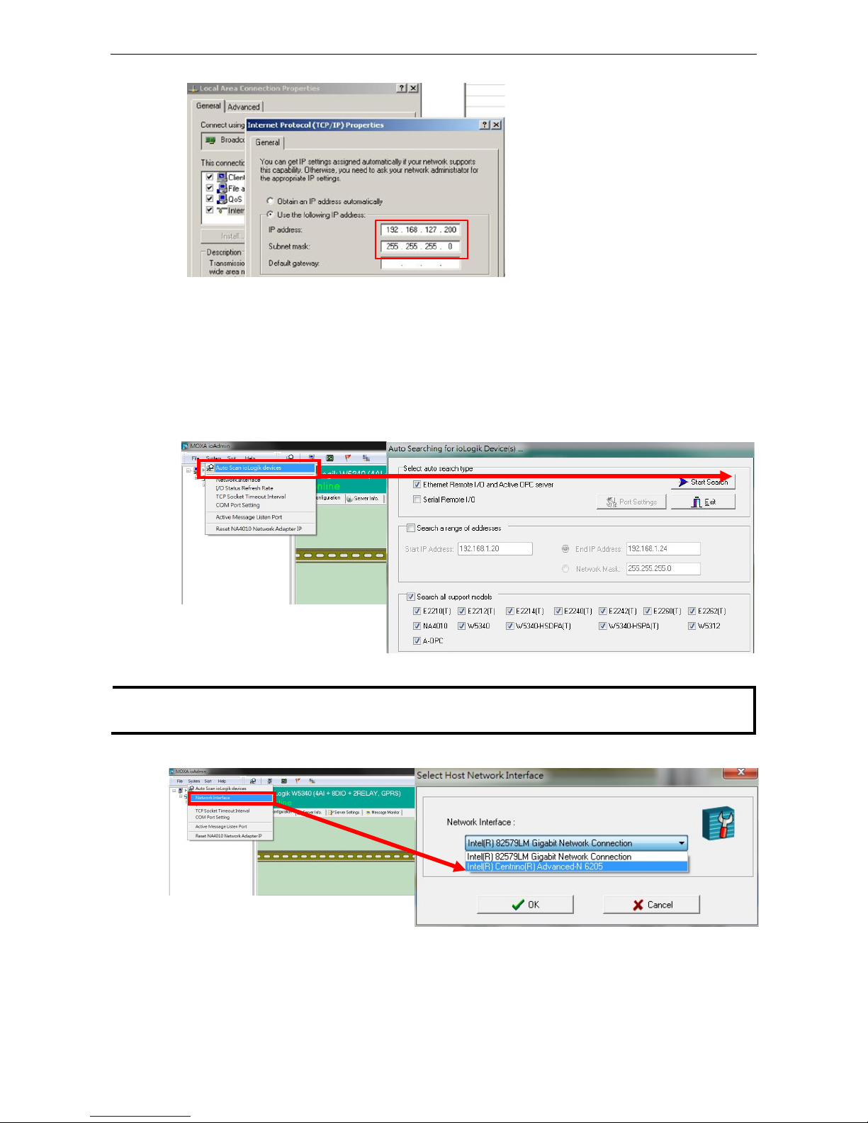
2. Set the host PC’s IP address to 192.168.127.XXX. (where XXX can range from 001 to 253). In
Windows, you can adjust this setting through the Control Panel
Network and Internet. The default
ioLogik device settings are:
Default IP Address Default Netmask Default Gateway
192.168.127.254 255.255.255.0 None
Page 18
ioLogik W5300 Getting Started
2-4
Example IP: 192.168.127.200
Activating ioAdmin and connecting to the ioLogik
1. To open ioAdmin, click the Start meny, then Program Files MOXA IO Server Utility ioAdmin.
2. When ioAdmin is started, it will automatically run the a search program to find all ioLogik devices on the
network to which you are connected. You may also click System on the menu bar, then select Auto Scan
ioLogik device. A dialog will appear. Click Start Search. Once the ioLogik has been detected, modify the
settings as needed for your network environment, and then restart the device.
NOTE
The
best approach to setting up a previously configured ioLogik is to first reset it to the factory default
using
the reset button
(see Chapter 1 for details). You can then use ioAdmin to configure the ioLogik.
3. If the host computer has multiple interfaces, be sure to select the correct one before searching.
Page 19
ioLogik W5300 Getting Started
2-5
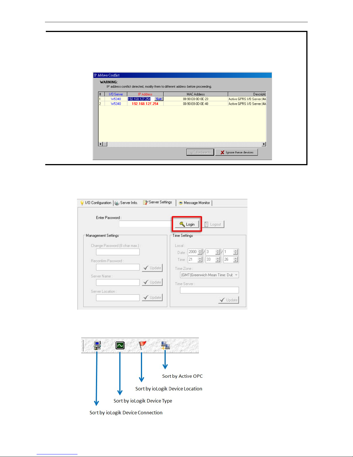
NOTE
If multiple ioLogik W
5300 units with the same default IP address are installed on the same network,
to avoid
IP conflicts
you will need to first
assign a different IP address to each unit. ioAdmin automatically detects IP
conflicts and gives you a chance to modify each
unit’s IP address in the IP Address column. Click the Set
button to reboot the
corresponding unit with its new IP address. Click the Re-Search button to
check if the
setting has been successful by
refreshing the list of units found by ioAdmin.
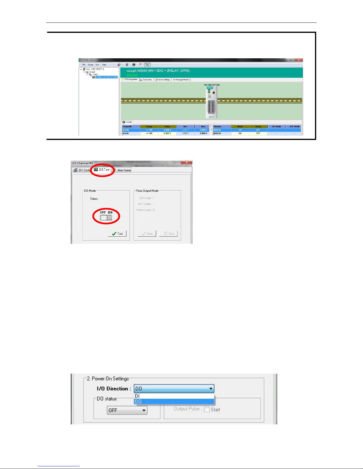
4. Login as administrator: For full access to all configuration options, log in as administrator from the
Server Settings panel. This is required whenever you start ioAdmin, or boot up or restart the ioLogik. When
you install the ioLogik for the first time, the password will be blank and you can simply click Login. If a
password has already been set, hold down the reset button to clear the password and load factory defaults.
5. Monitoring and Testing I/O status: Once your unit has been found by ioAdmin, you can view the status
of all attached I/O on ioAdmin’s main screen.
Page 20
ioLogik W5300 Getting Started
2-6
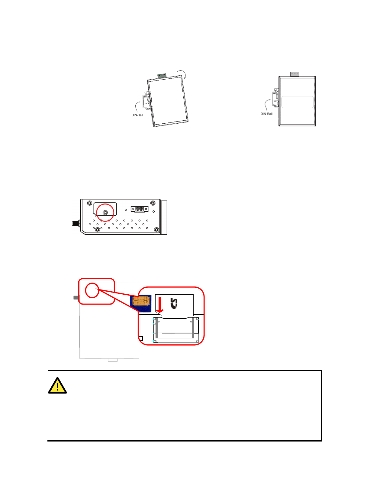
NOTE
ioAdmin supports four viewing options for the navigation panel. If you select
Sort by Active OPC server
, the
ioLogik W
5300 will appear in the Active OPC server group. Alternately, the same device
will be shown under
the
LAN group if you connect to the W5300 with Ethernet cables, instead of over the cellular network.
You can test each DO channel by opening the channel’s configuration window and selecting the Digital Output
Test tab.
After clicking the Test button, you can see how a channel’s status affects or is affected by the attached device.
For DO channels, you can set the on/off status to start and stop pulse output. For DI channels, you can monitor
the attached device’s on/off status, or monitor the counter.
You can now use ioAdmin to set up or configure your unit. Refer to Chapter 3 for additional information on using
ioAdmin.
Configuring Digital I/O Channels
The ioLogik W5300 product family is equipped with different I/O types, including analog inputs, digital inputs,
digital outputs, relay outputs, and software configurable DIOs, offering great flexibility for connecting I/O
devices such as software configurable DIO channels. Before you connect I/O devices and sensors, you should
configure the DIO channels as DI or DO. The W5340 for example comes with 4 DI channels and 4 DO channels.
However, the user has the option of redefining the function of these channels. Each DIO channel is configured
to act as either a DI or DO channel, according to the Power On Settings. To switch between DI and DO
channel operation, select the desired mode in the I/O Direction field under Power on Settings. After clicking
Apply, you will need to restart the ioLogik W5300 for the new setting to take effect.
Page 21

ioLogik W5300 Getting Started
2-7
Connecting I/O Devices
Unlike traditional Ethernet I/O products, the ioLogik W5300 can connect to analog sensors, dry contact, PNP,
and NPN sensors at the same time. The sensor type determines your wiring approach, as shown in the following
examples (this example shows the pin numbers for an ioLogik W5340 unit):
Analog Input
Digital Input Dry Contact:
Digital Input Wet Contact (Connect to NPN-type Sensor)
Digital Input Wet Contact (Connect to PNP-type Sensor)
Digital Output (Sink Type)
Page 22

ioLogik W5300 Getting Started
2-8
Relay Output
ATTENTION
When connecting the I/O device to the ioLogik’s dry contacts, we strongly recommend connecting DI.Com to
the power of the external sensor to avoid affecting other channels.
DI.Com input power should
be limited at
12 to 36 VDC.
ATTENTION
Sensor types are arranged in groups, with DI
O-0 to DIO-3 forming one group and DIO-4 to DIO-7
forming
another group. If an NPN sensor is connected to DI
-0, then only NPN sensors ca
n be connected to the other
DI channels in that group (i.e., DI
O-1, DIO-2, and DIO-3). Likewise, if a PNP sensor is connected to DIO-4
,
then only PNP sensors can be connected to the other DI channels in that group (i.e., DI
O-5, DIO-6, and
DI
O-7).
Testing I/O Devices
Power on the ioLogik W5300, try changing the I/O status, and then use ioAdmin to determine if the status has
changed under the I/O Configuration bar. (Refer to the figure below)
Page 23
ioLogik W5300 Getting Started
2-9
DIN Rail / Wall Mounting
The ioLogik W5300’s built-in mounting appendages are suitable for mounting on a flat wall or installing on a
DIN rail. Follow the instructions in the figures below to install the W5300 on a DIN rail.
STEP 1: Insert the top
of the DIN rail into the
slot.
STEP 2: The DIN rail
attachment unit will
snap into place as
shown at right.
Installing/Removing SIM and SD Cards
The ioLogik is equipped with two slots; one is for SIM cards and the other is for SD cards. The card reader slots
are protected inside the ioLogik device. You will need to unscrew and remove the card cover to install your SIM
and SD cards. When inserting an SD or SIM card, remember to keep the chipped side of the card facing down.
Follow these steps to remove or install a SIM or SD card:
1. Remove the screw holding the card cover in place.
2. There are two different card slot types used on the ioLogik series of devices:
(a) On ioLogik W5312 and W5340 models, directly insert or remove the SIM/SD card into the respective slot
(b) On the ioLogik W5340-HSPA you must first depress the card-locking mechanism to eject the card. Use
a pointed instrument like a ball-point pen to depresss the small yellow button at the side of the card slot.
This ejects the card tray, from which you may then insert or remove a SIM card.
ATTENTION
We strongly recommend using
the following SD cards, which have been tested in our laboratory:
•
Kingston SDHC 4/16/32 GB
•
Transcend SDHC 4/8/32 GB
•
Innodisk SD6 2/4/8 GB (These Innodisk SD cards are classified as wide-temperature products.)
The function is dependent on the firmware version. Be sure to use firmware version V1.3 or above for the
ioLogik W5312 series, and V1.5 or above for the ioLogik W5340 series.
Page 24
ioLogik W5300 Getting Started
2-10
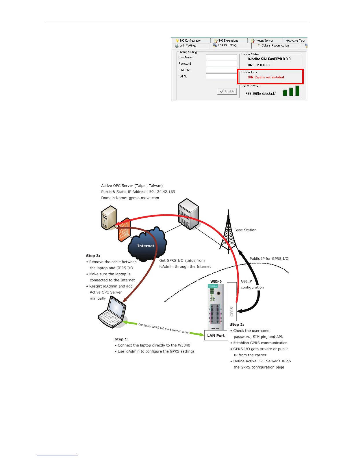
The SIGNAL LEDs on the front panel provide
a convenient way of checking if the SIM card
is installed properly. If the antenna is
installed and the network is operating
normally, then at least one of the three
SIGNAL LEDs should be illuminated at all
times. If none of the LEDs are illuminated,
then the SIM card may not be installed
properly. This is because the PIN code is
stored on the SIM card; if the PIN code
cannot be accessed, then the modem will not be accessible over the network. If the LED is not illuminated,
check the Error message shown on the ioAdmin “cellular settings” panel.
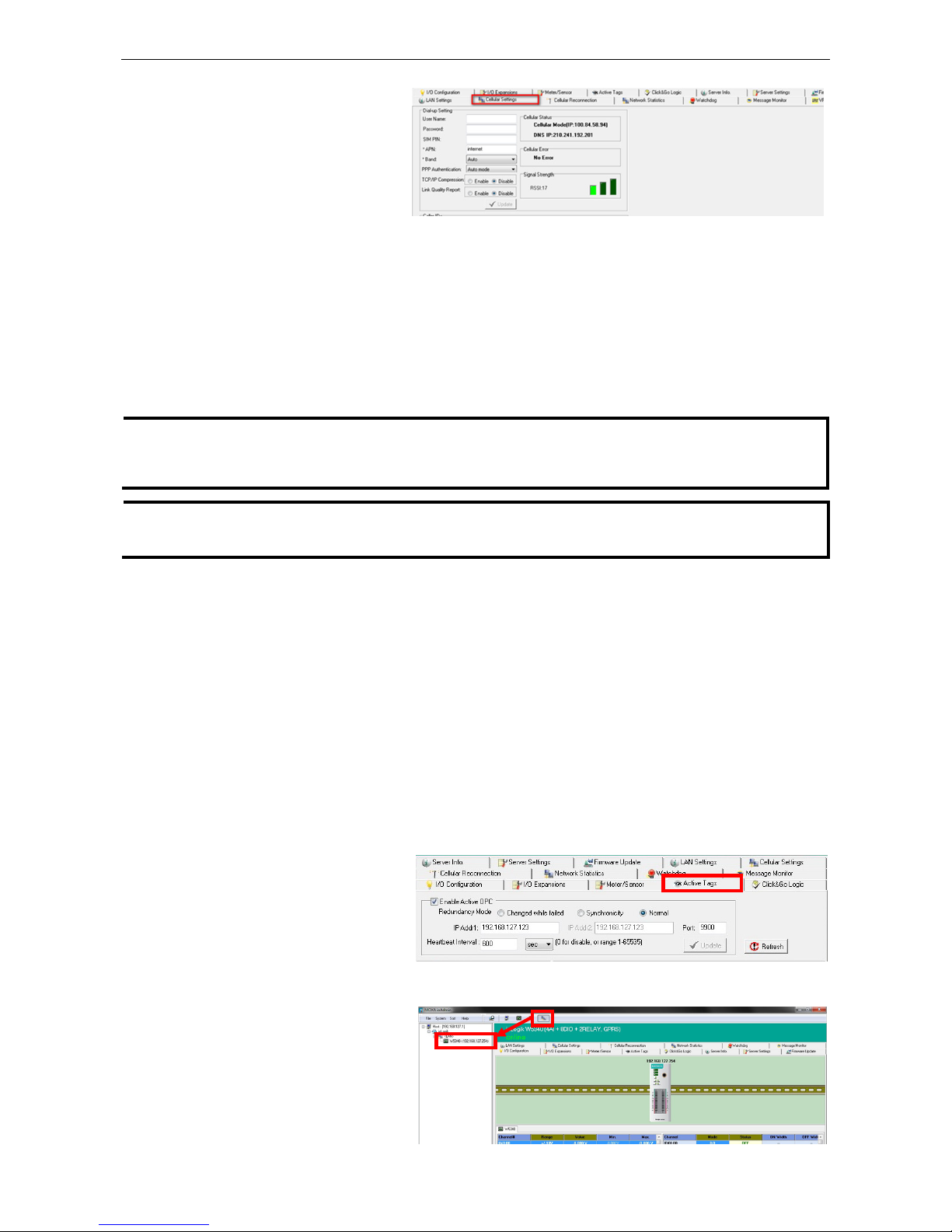
Connecting the ioLogik W5300 to a Cellular Network
When the environment is ready, follow these steps to test the ioLogik W5300 (refer to the figure below).
Step 1: Connect directly from the PC to the W5300 and use ioAdmin to configure the W5300’s cellular settings.
Step 2: For the ioLogik W5300, enter the user name, password, SIM Pin, APN, and define the Active OPC
server IP on the cellular settings page. Make sure the Operation Mode is correctly selected.
Step 3: Remove the cable connecting the PC and ioLogik W5300, re-open ioAdmin, and then add the Active
OPC Server manually. The checkmarked PC will receive Internet access first.
Detailed instructions:
1. Power off the ioLogik W5300.
2. Insert a SIM card that can connect to the cellular network.
3. Connect to ioAdmin via the Ethernet port of the ioLogik.
4. Power on the ioLogik and start ioAdmin.
5. After connecting ioAdmin and the ioLogik W5300, log in with the administrator password.
Page 25
ioLogik W5300 Getting Started
2-11
6. To set up your cellular
connection, click the Cellular
Settings tab and enter your
User name, Password, SIM pin
code, and APN of your Cellular
Provider (contact your local
Cellular Service Provider for
assistance) than click Update. When you click Update, the system will prompt you to restart to activate
the new settings.
7. The Operation Mode must also be correctly selected for your application.
(Default Operation Mode: Cellular Always On)
8. After rebooting, the W5300 will try to connect to the Cellular network, with the connection status shown in
the Cellular Status column. If the connection is established, the IP address will appear in this column. If
the connection is not successful, you will receive an Error message. Additional details can be found in
Appendix F.
9. For testing, Once you have obtained the public IP address for the ioLogik W5300, try to PING from the DOS
shell (e.g., type C\:>ping 61.56.74.10). If the W5300 is using a private IP, you can skip this step.
NOTE
Be sure to configure the LAN settings first to make sure the LAN IP Address is on the same subnet
as the PC running ioAdmin. Follow the instructions to restart the ioLogik and then proceed with the settings
on the Cellular Settings page.
NOTE
Be sure to select the Cellular Setting
Operation Mode Cellular Always ON when performing the
connection test.
Installing AOPC on a Host with a Static IP Address
Moxa’s Active OPC Server™ is an OPC software driver for an HMI or SCADA system. It seamlessly connects
Moxa’s ioLogik products to a wide variety of SCADA systems, including the most popular: Wonderware, Citect,
and iFix. Active OPC Server™ conforms to the OPC Foundation’s DA 3.0 data access standard. Active OPC
server must use public, static IP address.
1. To install Active OPC Server, insert the installation CD into the host computer. In the Software\Utility
directory of the CD, then locate and run setup.exe. The installation program will guide you through the
installation process and install the Active OPC Server utility. The OPC Core Components will be installed as
well. Active OPC Server can be downloaded from the Moxa Website, and may be found from the support
page, www.moxa.com/support/. After downloading the AOPC software, unzip it and run setup.exe. The
installation program will guide you through the installation process and install the Active OPC Server Utility.
For more details on AOPC installation and use, refer to the Active OPC User’s Manual.
2. Start the ioAdmin utility and set
up the Active OPC Server IP
address on the Active Tags
panel. ioAdmin will prompt you to
reboot the ioLogik W5300 after
clicking the Update button. Click
yes to restart the ioLogik.
3. Start Active OPC Server; a new ioLogik W5300 will be created.
4. In ioAdmin’s search menu,
manually add the IP address for
Active OPC Server. The ioLogik
W5300 will appear under Active
OPC Server. The ioAdmin search
menu is set by default to sort by
Active OPC.
Page 26
ioLogik W5300 Getting Started
2-12
5. You can now test and monitor I/O status in ioAdmin.
NOTE
In this scenario,
Active OPC Server is acting as middleware between the
central configuration/control software
and the ioLogik W
5300
remote I/O unit served over a cellular interface. To minimize bandwidth usage, click the
Refresh
button manually to retrieve the settings.
Import/Export a Configuration File
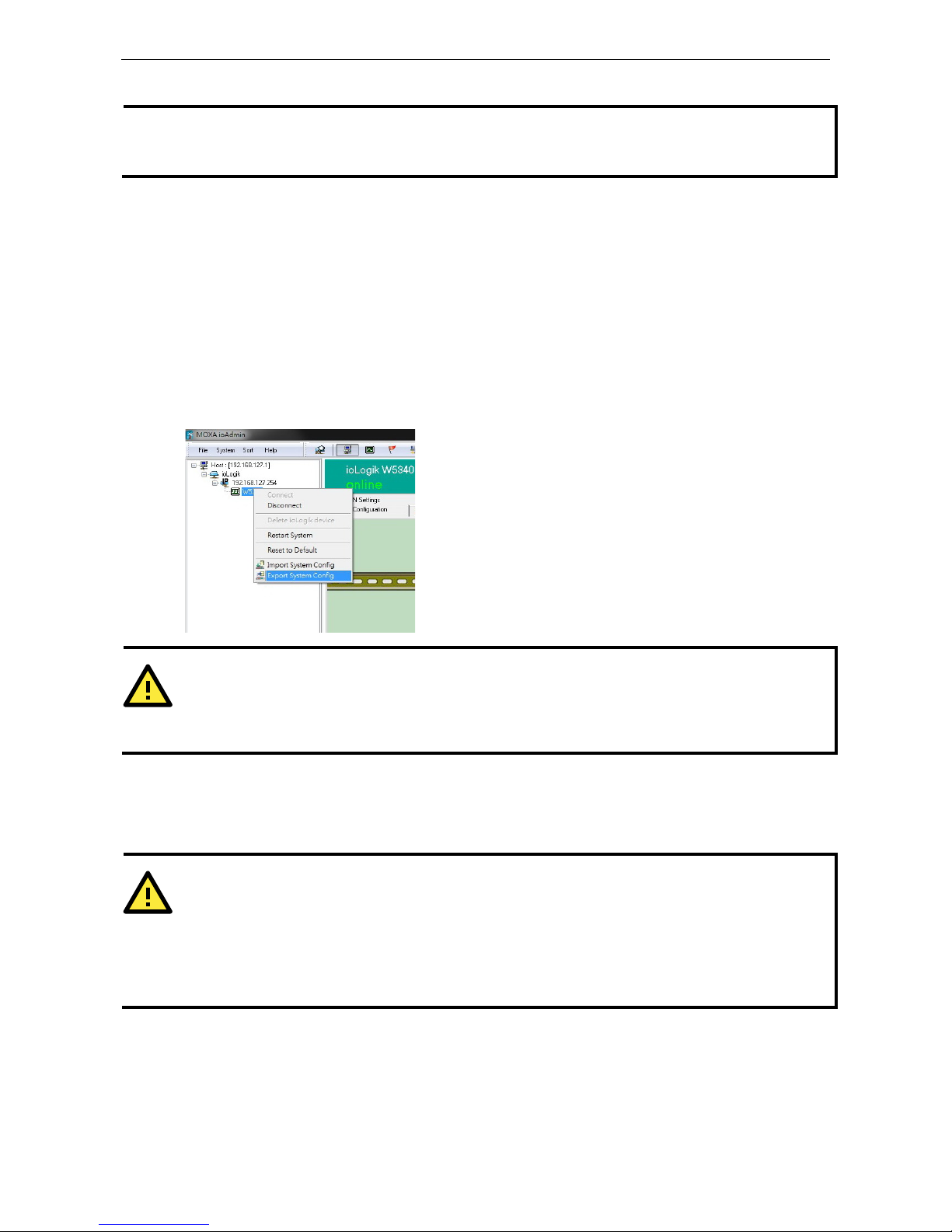
Using ioAdmin to Import/Export a Device Configuration
To import or export a system configuration right click on the I/O model name and then selection Import
System Config or Export System Config. You must be logged in as an administrator to use this command.
Export System Config
Select this command to export the selected ioLogik’s configuration to a text file. We recommend using this
method to back up your configuration after you have finished configuring the ioLogik for your application.
ATTENTION
Since there are major functional differences between firmware versions, exporting the configuration file
requires a longer processing time.
Adjust the TCP Socket Timeout Interval to 30 seconds when using
ioAdmin 3.10 or above, especially if earlie
r versions of ioAdmin have been installed and then removed.
Import System Config
Select this command to load a configuration for the selected ioLogik from a configuration text file. The new
configuration will not take effect until the ioLogik has been restarted. This command can be used to restore a
configuration after loading the factory defaults, or to duplicate a configuration to multiple ioLogik units.
ATTENTION
Since
there are major function differences between firmw
are versions, the configuration file is not compatible
if using firmware V1.3 or above for the ioLogik W5312 series, and V1.5 or above for the ioLogik W5340 series.
The configuration file cannot be imported into firmware versions earlier than the above versions.
Be sure to check your firmware version carefully before importing/exporting and upgrading
firmware.
Page 27

3
3. The ioAdmin Utility
In this chapter, we explain how to use ioAdmin to configure your ioLogik product.
The following topics are covered in this chapter:
System Requirements
Key Features
Using the ioAdmin Utility
The ioAdmin Utility Window
ioAdmin Menu Bar
The Wiring Guide
ioAdmin Quick-Link Buttons
ioAdmin Navigation Panel
Main Window
Synchronization Rate Status Bar
ioAdmin Status Bar
ioAdmin Configuration Panels
The Server Settings Panel
The LAN Settings Panel
The I/O Configuration Panel
Configuring AI Channels
Configuring Digital I/O Channels
Configuring Digital Input Channels
Configuring Digital Output / Relay Output
Channels
Testing DI and DO Channels
The I/O Expansion Panel
I/O Expansion: Step-by-Step
The Active Tags Panel
Active OPC: Redundancy Mode
The Cellular Settings Panel
Dial-up Setting
Caller IDs
Operation Mode
DDNS Settings
VPN Settings Panel (ioLogik W5340-HSPA(-
T)
only)
VPN System Log Events and Error Codes
Cellular Reconnection
Meter/Sensor
Network Statistics
Watchdog Panel
Click&Go Logic Panel
Page 28

ioLogik W5300 Utility: ioAdmin
3-2
System Requirements
ioLogik W5300 remote I/O units can be managed and configured over either an Ethernet or cellular network
using ioAdmin, a Windows utility provided with your ioLogik. ioAdmin’s graphical user interface gives you easy
access to all status information and settings. ioAdmin can also be used to configure Click&Go rules to provide
front-end event handling capabilities.
Hardware Requirements
CPU Intel Pentium (Pentium 4 and above)
RAM 512 MB (1024 MB recommended)
Network Interface 10/100Mb Ethernet
Software Requirements
Operating System Microsoft Windows 2000, XP or later
Editor(Not necessary) Microsoft Office 2003 (Access 2003) or later
NOTE
In this chapter, all of the descriptions are based on ioAdmin 3.10. The function, however, is dependent on the
firmware version. Use firmware version V1.3 or above for the ioLogik W5312 series, and V1.5 or above for the
ioLogik W5340 series.
Key Features
Remote Management
Over the Ethernet or Cellular network, ioAdmin allows users to:
• Search and configure multiple ioLogiks.
• Perform I/O status monitoring and control
• Use active message monitoring
• Use Click&Go local logic control configuration
• Use the firmware upgrade interface
• Restart the ioLogik
• Reset to factory defaults
On-line Wiring Guide
A wiring guide can be opened from within ioAdmin.
Configuration File
ioAdmin allows the entire configuration of the ioLogik W5300 series to be saved as a file. The file is viewable in
text format and serves three purposes:
• As a record or backup of your configuration.
• As a template for configuring other ioLogik W5300 units.
• As a quick reference guide for you to configure Modbus drivers in a SCADA system.
The file includes the following information:
• File title, Date, and Time
• Model Information
• System Configuration
• Modbus Address
Device Management List
ioAdmin can import and export a list of ioLogik devices that are being managed. This file can make it easier to
manage all devices on the network, and includes the following information:
• Device name
• Module
• IP address
• Unit ID
Page 29
ioLogik W5300 Utility: ioAdmin
3-3
Using the ioAdmin Utility
The ioAdmin Utility Window
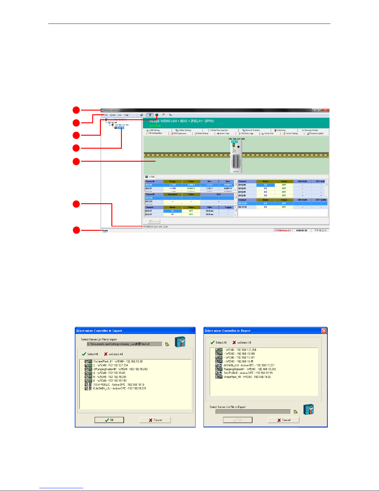
Below you see a screenshot of ioAdmin’s main window, with its main features highlighted. The window defaults
to the I/O Configuration Panel, which displays a figure of your unit and the status of its I/O channels. The
other tabs in the main window take you to device and network settings which become available once you log
into the ioLogik. Note that configuration options are not available until you log in as administrator.
1. Window title 3. Quick-link buttons 5. Main window 7. Status bar
2. Menu bar 4. Navigation panel 6. Sync. rate status
ioAdmin Menu Bar
Menu Bar: File
Here you can save, import, or export a configuration file or lists of servers and devices. When importing or
exporting device lists you will be prompted for source and destination devices with a popup window. You may
click on the Folder icon to select the device you will be retrieving the list from,or key-in the file name to
save/import a specific file.
The file will have an .SLT extension and can be opened as a text file. The server list will provide the basic
information for each server, such as Device Name, Model, IP address, and Unit ID.
1
2 3 4 5 6
7
Page 30
ioLogik W5300 Utility: ioAdmin
3-4
Menu Bar: System
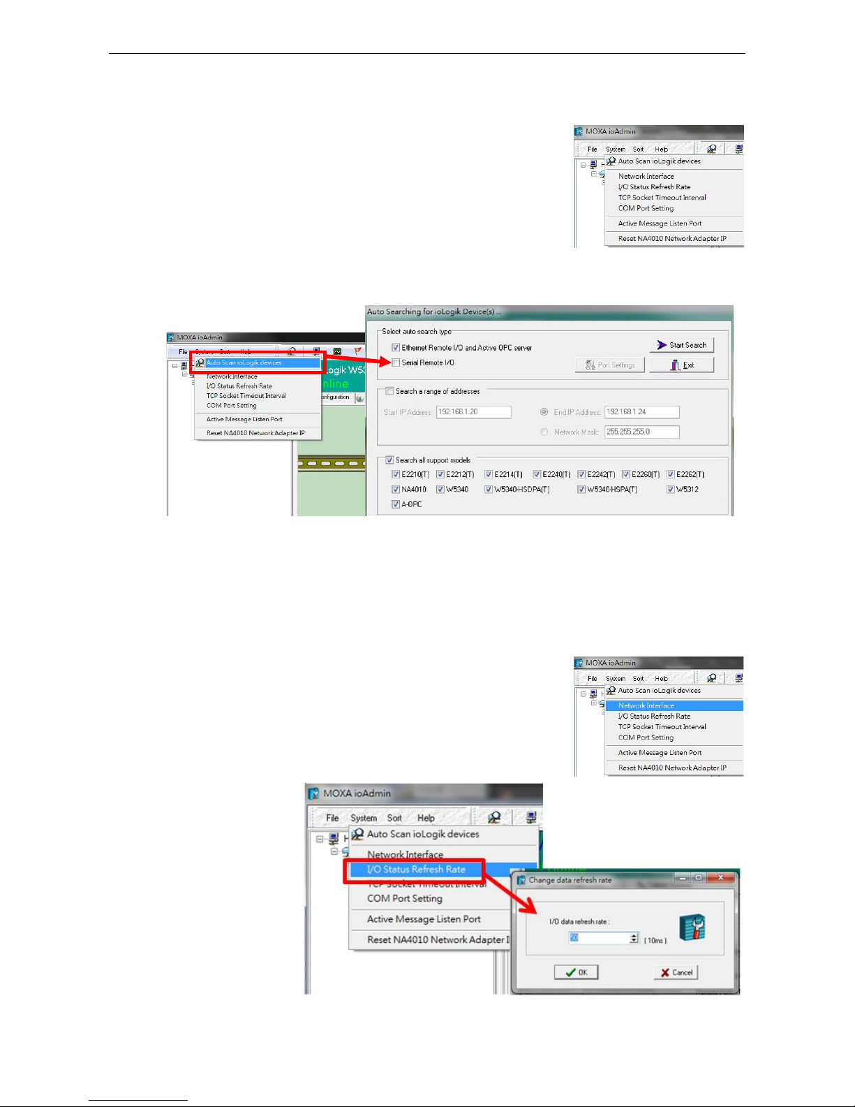
Several operations can be accessed from the System menu.
Auto Scan ioLogik Devices searches the network for connected ioLogik devices. This is useful when
connecting a new device for the first time, or when recovering from a network failure.
Auto-scan allows you to search according to Type, IP Range, or Model.
Type: Search for ioLogik remote I/O terminals by the type of connection, either Ethernet or Serial.
IP range: There are two ways to define a range of IPs to search: by entering a starting IP address and an
ending IP address in the appropriate boxes, or by using a netmask with a starting IP address.
Model: Search for selected models; click all that you are interested in finding.
Click Start Search to begin. Whenever a device is found, it will display in the lower portion of the window.
Network Interface: If the PC has multiple network adapters installed, this
allows you to select which NIC the device will connect over. The default
network interface will be the same as the one set in Windows. If the ioLogik
device is not connected to the selected interface, the PC will not be able to
detect it.
I/O Status Refresh
Rate is used to adjust
how often the ioLogik is
polled for device status
by the ioAdmin utility.
The current rate is
displayed on the status
bar at the bottom of the
window.
Note: Higher sync
rates result in higher
loads on the network.
Page 31

ioLogik W5300 Utility: ioAdmin
3-5
TCP Socket Timeout Interval allows you to set a timeout period when attempting to establish a connection
over a TCP socket. If the ioLogik cannot connect to a server within the specified time period, it will automatically
release the modbus/TCP connection to free up the port for the next attempt. (Default: 30 seconds)
COM Port Setting is used to set the default serial communications parameters so the ioAdmin utility may
establish a Modbus connection. The fields are baud rate, data bits, stop bits, parity, and timeout interval.
For most applications, this will involve connecting to ioLogik R-series devices.
Active Message Listen Port specifies the port number over which the ioLogik will listen for Active Messages.
If the active messages are traveling across a network firewall you must be sure to open the port on your firewall
settings to ensure that messages can get through.
Page 32

ioLogik W5300 Utility: ioAdmin
3-6
Reset NA4010 Network Adaptor IP is used to re-assign an IP address to the NA-4010 network as reported
by the ioLogik W5300 series adapter.
Menu Bar: Sort
The Sort menu re-orders the list of devices shown in the navigation
panel according to their connection/IP address, model, location
(as defined in the location field, aa 58 character descriptor that may
be set in the Server Settings Panel), or whether or not the device
suports an Active OPC client.
The Wiring Guide
ioAdmin provides a wiring
guide for the ioLogik W5300
series. You can access the
wiring guide by
right-clicking the ioLogik
figure in the I/O
Configuration panel, or
by clicking on the Wiring
Guide icon in the
submenuat the top of the
windo. The wiring guide is a
help file showing wiring
information and electrical
characteristics for various
types of connection.
You can also access the
wiring guide online, by
clicking on the links
provided in the Help menu
on the menu bar.
Page 33

ioLogik W5300 Utility: ioAdmin
3-7
ioAdmin Quick-Link Buttons
Quick links are a collection of commonly used features. Starting with the rightmost icon, they include search,
and a series of sorting buttons: by connection, by device type, by the device’s 58 character location descriptor
(defined in the Server Settings Panel), or show all devices which have an AOPC client installed on them.
Auto-Scan ioLogik Devices
Auto Scan ioLogik devices allows users to search and locate an ioLogik on the same physical
network, or specify a remote IP address to connect to a remote ioLogik.
Sorting Views
These buttons give four different ways of re-ordering devices in the
ioAdmin navigation panel. The icons are shown at right, and
explained in the table below.
ICON Navigation Panel View
Sort according to the connection:
using subnets and IP addresses
Sort according to device type
using the ioLogik model number
Sort by the ioLogik’s location
field; this is
a descriptor that is defined in the
ioAdmin’s Server Settings Panel
Show all devices that support an Active
OPC client
NOTE
The default location is
Empty. If you have not set the location field when setting up the ioLogik W5300
, the
navigation panel will
register its location as Empty, and group all devices configured so together.
ioAdmin Navigation Panel
The navigation panel shows an overview of every configured ioLogik device currently connected to the network,
with devices ordered according to the selected sorting method (see above). The default view is By
Connection. You can choose a different sorting method by clicking the quick-link buttons at the top of the
navigation panel.
Page 34

ioLogik W5300 Utility: ioAdmin
3-8
The navigation panel offers many functions (such as connect and disconnect). Advanced functions require
administrator rights. The action menu is accessed by right clicking on the server’s model name in the
navigation panel.
Basic Functions: Add, Connect, and Disconnect
Add ioLogik ioLogik device: Right click an ioLogik tag, then select
this command to manually add an ioLogik device or Active OPC server.
Connect: Attempt to connecting to the selected device over the
network.
Disconnect: Drop the network connection to the selected ioLogik.
Advanced Functions: Delete, Restart, Reset, Import/Export Config
You must be logged in as administrator to use these commands.
Delete ioLogik device: Select this command to remove the
selected ioLogik from the navigation panel. To successfully delete a
device from the device list shown in the navigation panel, the
target must first be disconnected from the network. Once deleted,
a device must be reconnected to the network using the ioAdmin
search process, described above.
Restart System: Select this command to restart a selected
ioLogik RTU.
Reset to Default: Select this command to reset all settings on the selected ioLogik, including the password
and all configuration settings, to factory default values.
Export System Config: Select this command to export the selected ioLogik’s configuration to a text file. We
strongly recommend that you use this to back up your configuration after you have finished configuring the
ioLogik for your application.
Import System Config: Select this command to load a configuration for the selected ioLogik from a
configuration file. The new configuration will not take effect until the ioLogik has been restarted. This command
can be used to restore a configuration after loading the factory defaults, or to duplicate a configuration to
multiple ioLogik units.
Page 35

ioLogik W5300 Utility: ioAdmin
3-9
Main Window
The main window allows users to view I/O status, ioLogik system information, and check messages from the
message monitor without requiring logging in to the ioLogik. However, you will need to log in to perform
configuration and operation tasks.
I/O Configuration Panel (General)
The I/O Configuration panel shows the status of every I/O channel. This is the default panel when you first
open ioAdmin. Input channels are listed on the left and output channels are listed on the right. For more
information about configuring I/O, see the section I/O Configuration Panel, below.
Server Info Panel
Information such as the device name, configured IP address, and firmware version, is displayed on the Server
Info panel. This panel allows you to look up the Cellular IP address whenever you need it.
Page 36

ioLogik W5300 Utility: ioAdmin
3-10
Server Settings Panel (General)
Click the Server Settings tab to log in as an ioAdmin
administrator. This is required to gain access to the
ioLogik configuration options. If a password has not
been set up, simply click Login and leave the
Password field blank.
Message Monitor Panel (General)
The Message Monitor will
display any TCP/UDP Active
Messages reported by the
ioLogik W5300. When you
install the unit for the first time,
the ruleset will not have been
defined yet, so there will be no
messages on the monitor.
When a ruleset has been
defined and activated, any
TCP/UDP messages that have
been triggered by sensor
events will be shown on the
monitor.
Messages can be displayed in ASCII, HEX, or 2-byte Unicode (UCS2). To select your preferred code, check the
appropriate button at the bottom of the window. Unicode supports multiple languages.
Synchronization Rate Status Bar
The current sync rate is displayed on the bar at the bottom of the window. The number shows how often the
ioLogik is polled for device status from the ioAdmin utility. The rate can be adjusted by clicking Menu Bar
System I/O Status Refresh Rate. Higher sync rates result in a higher network load.
ioAdmin Status Bar
The status bar shows
ioAdmin status
information, such as
program status (ready,
searching), ioLogik I/O
details, and system time.
Page 37

ioLogik W5300 Utility: ioAdmin
3-11
ioAdmin Configuration Panels
For full access to all configuration options users must log in as administrator from the Server Settings panel.
This is required whenever you start up ioAdmin, re-boot, or restart the ioLogik. When you install an ioLogik for
the first time the password will be blank; in this case, just click Login, no password is required. Additional
functions are available after logging in, including the following tabs:
When making configuration changes, you will need to click Update or Apply to save the changes. Some
changes will require that the unit be restarted in order to take effect.
ATTENTION
You MUST log in
as administrator to access the Network, Watchdog Timer, and Firmware Update
panels.
If you forget the password, hold down the
reset button to clear the password and load factory defaults.
This
will result in the loss of all configuration settings and
any Click&Go logic that may have already
been configured.
The Server Settings Panel
In the Server Settings panel you can configure Management Settings like password, server name, and
server location. ioAdmin supports long server names and a location description of up to 58 chars. You can also
configure Time Settings such as local date and time, time zone, and time server under the Server Setting
Panel. For example, you can use tock.stdtime.gov.tw.
NOTE
The
server also relates to the node created in the Active OPC Server.
Page 38

ioLogik W5300 Utility: ioAdmin
3-12
The LAN Settings Panel
The LAN Settings panel is available after you log in as administrator. You will be able to configure IP,
Modbus/TCP Alive Check Timeout, DNS, and SNMP settings.
IP Settings
You can set up a static or dynamic IP address for the ioLogik, as well as a subnet mask and gateway address.
To allow only authorized IP addresses to have access to the ioLogik and attached sensors, click Accessible IP.
Access will be granted only to addresses listed in the Accessible IP screen. Any requests from sources that are
not on the accessible IP list will be unable to use Modbus/TCP or ioAdmin to access the ioLogik.
Modbus/TCP Alive Check Timeout Settings
Modbus/TCP Alive Check Timeout is designed to avoid TCP congestion due to a connection failure. If the
network host is unable to respond due to a hardware failure or a network problem, the ioLogik will continue to
wait for a response from the host. This will cause the TCP port to be occupied indefinitely by the host. On the
other hand, if an idle connection timeout interval is enabled for Modbus/TCP, then when the ioLogik’s connection to the
server exceeds a specified time period the device will automatically release its modbus/TCP connection to the server, freeing
up the port for a new connection.
DNS Settings
Use this field to specify the IP addresses of one or two DNS servers. DNS servers can be used to find available
e-mail addresses when setting up Click&Go rules. By default, DNS is set to automatic. If you want to configure
a specific setting, contact your local cellular provider for details.
SNMP Settings
The ioLogik W5300 supports SNMP v1 and v2c (Simple Network Management Protocol) to monitor network and
I/O devices. It is useful for building automation and telecom applications. Use these fields to enable SNMP and
to set read and write strings.
Page 39

ioLogik W5300 Utility: ioAdmin
3-13
The I/O Configuration Panel
When logged in as administrator, click on the I/O Configuration tab and double click on one of the channels
listed below to configure that channel’s settings. A window for that channel will open, showing the configuration
options. After the channel has been configured, click Apply to implement the new settings.
NOTE
Right click the window to change the view to show or not show the product picture.
Horizontal View include
s
the product picture, whereas
Vertical View does not show the product picture.
Configuring AI Channels
The ioLogik W5340 and
W5340-HSPA are both equipped
with 4 AI (analog input) channels
that can be set individually to ±5 V,
±10 V, 0 to 10 V, 0 to 20 mA, and 4
to 20 mA. You may also set all channels at once using the Apply to all channels check box (left figure, below).
Alias Name (right figure, below) lets users configure the alias of an AI channel. The alias can be monitored by
the ioAdmin utility, or can be queried using either a user-defined program based on the Moxa MXIO library, or
a standard Modbus/TCP protocol.
Page 40

ioLogik W5300 Utility: ioAdmin
3-14
Users can increase the sampling rate on devices using one channel by disabling the unused AI channel by
un-checking the Enable Channel checkbox, in the upper left corner of the window.
Enabling Auto Scaling will linearly convert the actual current or voltage value into other user defined units,
such as percentage or ppm (parts per million)
Two scaling methods: slope formula, and slope-intercept
Auto Scaling with the point-slope formula can help to
eliminate high- and low-end extremes. For example, if 17
mA represents the highest allowable temperature, then it
is not necessary to allow higher temperature values. You
may then cut off any values beyond 17 mA and convert
those to a proprietary danger level, such as Level 5.
Auto Scaling with the slope-intercept formula
provides linear conversion with one ratio (M) and offset
(D). Offset can be an initial value of field device. Ratio can
help enlarge or reduce the scale by specifying a proportion.
It is also easy to modify the values in the database if we
need to use new ratio and offset values in the future.
The Reset Min and Reset
Max buttons will clear the
minimum or maximum
values recorded and
displayed in the ioAdmin
main window.
Configuring Virtual Channels
The ioLogik W5300 has 10 internal virtual channels to support front-end statistics functions like Maximum
Value (Max), Minimum Value (Min), Average Value, Accumulation, Instantaneous, and Incremental.
Page 41

ioLogik W5300 Utility: ioAdmin
3-15
The data source is the real I/O channel, such as AI and DI counters, some of which need to be converted to the
appropriate time unit. The operation is illustrated below.
After double-clicking on a virtual channel a popup window will appear (see below). First select the physical
source I/O. There are three types: AI, Counter, and I/O via Expansion Modules.
Next, choose the statistics function and time interval. There are six functions: Max, Min, Average,
Accumulation, Instantaneous, and Incremental. The time unit can be set to minutes or hours, with a
maximum value of 1440.
For example, if you want to monitor the daily flow at a point in a pipeline, you can use a pulse output flow meter
where 1 pulse indicates 5 ml. We can set the virtual channel’s scaling function so that 1 tick of counter input
equals 5 ml. Next, we set the Accumulation flag, and configure the Time Interval to 24 hours. This will set
up the virtual channel to log the total water flow volume over a period of 24 hours.
NOTE
Virtual channels are required to
configure AI or counter channels. For c
ounter channels, configure the
Counter Scaling
on the I/O Configuration panel before setting other operations in the virtual channels.
Configuring Digital I/O Channels
Digital I/O channels may be configured
for either input or output. When the
ioLogik W5300 is turned on, each digital
I/O channel will be configured to act as
either DI or DO, according to the Power
On Settings. To switch a channel
between input and output, select the
Use Virtual Channel to get the value, such as Max, Min,
Average, Accumulation, Instantaneous, and Incremental
Scale the value to a new unit
(This step may be skipped.)
AI Data
Counter Value
Display in
ioAdmin
Update to
AOPC
Page 42

ioLogik W5300 Utility: ioAdmin
3-16
desired mode in the I/O Direction field under Power On Settings. After clicking Apply, you will need to
restart the ioLogik W5300 for the new setting to take effect.
Configuring Digital Input Channels
The ioLogik W5300 can provide up to 12 digital
input (DI) channels. To configure software filtering
for a channel, set the Mode dropdown in section 1
Mode Settings to Filter. Software filtering is used
to avoid switch bounces. The filter is configurable in
multiples of 0.5 ms and accepts values between 1
and 65535. For example, a setting of 100 would
mean a 50 ms filter (100 × 0.5 ms).
The Mode dropdown may also be used to set the channel as straight Input (DI), or as an Event Counter.
Type On Off
Dry contact Short to GND Open
Wet contact 0 to 3 VDC 10 to 30 VDC
When set as an Event Counter, the channel will accept limit or proximity switches, and will tabulate ON/OFF
signal events. When Lo to Hi is selected, the counter value increases when an attached switch/circuit is closed.
When Hi to Lo is selected, the counter value increases when an attached switch/circuit is released. When Both
is selected, the counter value increases when attached the switch/circuit is successively closed and opened.
Page 43

ioLogik W5300 Utility: ioAdmin
3-17
Counter Scaling
After configuring a DI channel as an Event Counter, an additional Counter Scaling tab will indicate how often
the counter should be updated during the time unit specified for the virtual channel. For example, if the device
is configured to Update every 5 sec in the Counter Scaling tab, and the Virtual Channel is configured for Time
Interval = 1 min, and has Accumulation flagged, then as each minute passes this virtual channel will log the
total of the last 12 counter updates.
The counter value resets to zero whenever power is disconnected. To make sure the counter value is saved
whenever power is disconnected, select Save Status on Power Failure. Once power is reconnected the value
will remain the same as when power was cut.
To enable the counter to resume counting immediately upon powering up, go to the Power On Settings
section of the DI Config tab. The counter starts logging signals only after configured to do so by a Modbus or
a Click&Go command. You can also specify counting to begin automatically whenever the ioLogik is powered on.
To configure automatic counting, select Start under Counter mode parameter in the Power On Settings,
which is located under the DI Config tab within the DI Channel Window.
You can configure how a counter behaves during a network disconnect by navigating to the Watchdog panel
(click on the Watchdog tab in the main window) and configuring the Safe Status Settings and Host
Connection Watchdog. When the watchdog is enabled, any disconnection from the network will activate a
safe state; the counter may be configured to continue counting throughout the safe state by selecting
Start/Continue (found under the Counter Mode Parameters). If Start/Continue is not enabled, the
counter will suspend counting. If the Host Connection Watchdog is not enabled, then 阿 Safe Status
Settings will be ignored and the counter will continue counting during a network disconnection.
ATTENTION
The
Host Connection Watchdog is disabled by default and must be enabled for Safe Status Settings
to
take effect.
The Apply to All Channels option applies all settings to all DI channels on the selected device.
Page 44

ioLogik W5300 Utility: ioAdmin
3-18
Configuring Digital Output / Relay Output Channels
The ioLogik W5340 and W5340
HSPA can be configured to
provide up to 8 digital output
channels and 2 relay output
channels, while the ioLogik
W5312 provides up to 12
digital output channels. All of these channels may be treated as output channels. A DO channel can be set to
either DO or Pulse Output mode.
Digital Output Mode Pulse Output Mode
In digital output mode, the specifications are as follows.
Type OFF ON
DO mode Open Short
In Pulse Output mode, the selected digital output channel will generate a square wave as specified in the
pulse mode parameters. The low and high level widths are specified in multiples of 0.5 ms for Digital Output
(1.5 s for Relay output), with a maximum setting of 65,535. For digital output, you would enter 1000 for a width
of 500 ms. If the OFF width value is 5000 and the ON width value is 5000, the pulse output would be a square
wave with a 5-second pulse cycle. You can specify between 1 and 4,294,967,295 pulses; 0 indicates a
continuous pulse output.
When the ioLogik is first powered on, the status of each DO channel is set to OFF by default. This behavior can
be modified using the Power On Settings, located on the DO Config tab. You can set a DO channel to turn
ON or to commence pulse output whenever the ioLogik is powered on.
Page 45

ioLogik W5300 Utility: ioAdmin
3-19
Relay Count Monitoring
Two types of relay counts can be recorded in the ioLogik W5340: Total Counts and Current Counts. Relay
Total Counts records the total number of times a relay output channel has been triggered in its lifetime. In
general, each relay output channel can be used an average of 100,000 times. Users can monitor these counts
to see when the module should be replaced, or to switch to a different channel if the total count approaches the
upper limit.
Current Counts
allows the counter to
be reset to zero so
that relay triggers may be measured in batches. For example, if RLY-0 is connected to an external relay control
board, you can monitor the current counts to see when to replace the external relay component before it fails.
Last Reset Time records the last time Current Counts was reset. Both Total Counts and Current Counts
will be saved when there is a power failure. The Last Reset Time will be saved whenever the user manually
presses the Reset to Zero button.
You can control how a digital output / relay output channel
acts when the network is disconnected by navigating to
the Watchdog tab in the main window panel and setting
the appropriate parameters in the Safe Status Settings
and the Host Connection Watchdog panels. When the
Host Connection Watchdog is enabled, a network
disconnection will activate a safe state. The DO channel
can be configured to turn on, turn off, or commence pulse
output during the safe state. If the Host Connection
Watchdog is not enabled, then the DO/Relay Output
channel status will remain unchanged during a network disconnection.
ATTENTION
The
Host Connection Watchdog is disabled by default and must be enabled for Safe Status Settings
to
take effect.
Testing DI and DO Channels
You can test each channel by opening the channel’s configuration window (by clicking on its entry in the I/O
configuration panel in the main window) and selecting the Test tab.
Digital Input Test:
Digital Ouput Test:
Use the Test panel to see how a channel’s status affects or is affected by the attached device. For DO/Relay
Output channels, you can set the on/off status or start and stop pulse output. For DI channels, you can monitor
the attached device’s on/off status, or monitor the counter.
Page 46

ioLogik W5300 Utility: ioAdmin
3-20
Alias Name
Alias Name helps users configure the alias of a DI or
DO/Relay Output channel and define the status for On/Off as
Open/Closed or Closed/Open. The alias can be monitored by
the ioAdmin utility, and can be queried using a user-defined
program based on the Moxa MXIO library, or a standard
TCP/Modbus protocol.
The I/O Expansion Panel
The ioLogik W5300 may be configured to serve up to three daisy-chained ioLogik E1200 external I/O
expansion units. The ioAdmin utility cannot be used to define signal parameters for the the ioLogik E1200s
input and output channels; this must be done by connecting to the ioLogik E1200 using the ioSearch utility.
However, once the basic signal and channel parameters are defined this hardware configuration may be
exported to the ioLogik W5300 and then higher-order logic may be configured using the ioAdmin Click&Go,
Active Tags, and Data Logging panels. The maximum number of expansion modules allowed is three.
E1200 expansion units do not need to be directly connected (e.g., they may be connected using a switch), but
they must be installed on the same network segment as the ioLogik W5300, or they will not be detected. To
configure an E1200 expansion unit for use with the ioLogik W5300, follow these steps:
1. Start ioSearch, and use it to detect your ioLogik E1200 external expansion modules.
2. Configure the signal parameters for each I/O channel.
3. Save the configuration to a file.
4. Use ioSearch to import the configuration file to your local drive.
5. Open ioAdmin, and open the I/O Expansions panel.
6. Load the E1200 configuration file into ioAdmin by pressing the Add button and indicating the filepath.
7. Repeat steps 1 through 6 for any other ioLogik E1200 units you wish to configure.
8. Restart the ioLogik W5300.
After the restart ioAdmin should automatically detect your ioLogik E1200 devices. You may now use ioAdmin’s
Click&Go, Active Tags, and Data Logging panels to complete the configuration of the I/O expansion units.
Once the devices are detected, you should see them listed in the I/O Expansions panel as shown below.
Page 47

ioLogik W5300 Utility: ioAdmin
3-21
The Slot# column shown in the I/O Expansion panel will list the ioLogik E1200 units in the order their
configuration files are added. This means that if you first import the device closest to your ioLogik W5300,
that device will be listed as Slot# 1. If you then add the E1200 that is most distant from the W5300 (i.e.: the
module that is last in the chain), that module will be listed as Slot# 2, while the middle device (second in the
chain) will be added last, and so listed as Slot# 3. To avoid confusion, please make sure that you add the
devices in the order that makes the most sense for your topology.
The I/O Expansion panel will show the Modbus Address; the list of Modbus addresses may be exported to
a local file using the Export button.
ATTENTION
The following ioLogik E1200 models
may be used as external I/O expansion units:
E1210
(16 DIs), E1211 (16 DOs), E1212 (8 DIs and 8 DIOs), E1213
(4DI, 4 source DO, 4 DIO (source DO),
E1214
(6 DIs and 6 Relays), E1240 (8 DIs), E1241 (4 AOs), E1242 (4 AIs, 4 DIs, and 4 DIOs), E1260
(6
RTDs), and
E1262 (8TCs).
In addition to the models listed above, all
E12XX-T models may also be used for external I/O expansion.
Please keep in mind that
ioLogik E12000 expansion units can only be used with ioLogik W5300 series using
the
following
firmware versions:
W5312
: V1.3 and above; W5340: V1.6 and above; W5340-HSPA: V1.3 and above
W
5340 models with firmware v1.5 can support these 5 models: E1210, E1211, E1212, E1214, and E1240.
I/O Expansion: Step-by-Step
Step 1: Use ioSearch to configure the signal parameters for each ioLogik E1200 I/O channels
First, configure the E1200 device for connection to the network. For details on how to do this, please refer to
your ioLogik E1200 Users’ Manual. Please note that all expansion modules must reside on the same network
segment as the ioLogik W5300.
Next, use the ioSearch
Utility to detect all
available E1200 devices
on the network. If you do
not have ioSearch
installed on your local
computer, you may also
enter the IP address of a
remote E1200 into a web
browser to connect the
E1200’s web console,
which will automatically
serve the E1200’s
configuration utility over
HTTP. A screenshot of the
configuration utility is
shown below.
After bringing up the
configuration utility you
may now use the left menu to navigate the utility and configure signal parameters for the I/O channels. When
you are done, save these into the E1200’s configuration file.
Step 2: Export the configuration file from the remote ioLogik E1200 to your local host.
You may save the E1200’s configuration file on your local machine by using the Export System Config button
located on the menu at the left of the configuration utility (shown on the screenshot just above).
Page 48

ioLogik W5300 Utility: ioAdmin
3-22
Step 3: Use ioAdmin to add the configuration file to the ioLogik W5300.
Open ioAdmin and choose the I/O
Expansions tab. Export the E1200’s
configuration file to the W5300 by
pressing the Add button. This will bring
up a dialog that will allow you to browse
your file system and select the correct
filepath.
Step 3: Connect the ioLogik W5300 and E1200.
Connect the W5300 to the first E1200 I/O expansion module using an Ethernet cable via the RJ45 port. You
may then daisy chain the second and third expansion modules using the E1200’s switched Ethernet ports.
Step 4: Restart the ioLogik W5300.
After you have exported the configuration files into the w5300’s ioAdmin utility, restart the ioLogik W5300.
Open ioAdmin and log in. The ioLogik W5300 and expansion modules will be shown on the screen, with the IP
address of a device listed above the device. When you add an I/O expansion module, such as the ioLogik E1210
or E1211, additional tabs will appear, as shown below.
Step 5: Use ioAdmin to configue the higher order logic for the expansion modules.
Click on the I/O Expansion tab to check I/O
status for individual devices, or to set the alias for
a selected I/O channel. You may also use the
Click&Go, Data Logging, and Active Tags
panels to configure automated behavior and
routines for each E1200 I/O terminal.
NOTE
You cannot configure the
E1200’s I/O channels usihg ioAdmin. The configuration must be done with t
he E1200
configuration tool
, either over the web console or using ioSearch.
Page 49

ioLogik W5300 Utility: ioAdmin
3-23
The Active Tags Panel
When logged in as administrator, fill in the fixed IP address on the Active Tags panel to configure address and
port settings for Active OPC. The Active OPC Server Address may use either an IP address or a URL. The
default port number is 9900. The port number should be the same as the one set as the Active OPC Server’s
Active Tag Listen Port. After the OPC and channel tags have been configured, click Create Tags. The ioLogik
W5300 must be rebooted in order for the settings to take effect.
The Heartbeat Interval configures the period of time for the heartbeat signal to the AOPC server; this is used
to confirm the connection between an ioLogik device and the Active OPC server is live. If the heartbeat interval
is set and the network between the ioLogik and Active OPC server is down, the AOPC panel will detect the
heartbeat has stopped and will display BAD in the Quality column to indicate the loss of connectivity.
Setting the heartbeat interval to 0 disables it. When the heartbeat is disabled, the SysConnect tag on the
Active OPC server will always be 1, indicating that the AOPC server will not know if the connection state is live
or dead.
Active OPC: Redundancy Mode
The Active Tags panel offers three AOPC redundancy modes: Normal, Synchronicity, and Change while
failed.
Page 50

ioLogik W5300 Utility: ioAdmin
3-24
Normal
No redundancy: connects to a single
Active OPC.
Synchronicity
Synchronizes with 2 Active OPC
servers at the same time.
Change while failed
Tries to connect with the first Active
OPC Server IP. If it cannot connect,
it will automatically connect with the
second IP, and when the connection
to the second IP fails, it will switch
back to the first IP.
Heartbeat Interval
Tag updates are event-driven, and only change when a configured I/O event occurs; if the status remains
unchanged, tags are not updated to Active OPC server, and so the server will not know if a device remains
active or has gone down. To remedy this, a heartbeat signal can be used to verify for the AOPC server that the
ioLogik device remains active, over a live connection. If a heartbeat is configured and the connection between
the ioLogik and AOPC server is broken, the AOPC server will detect that the heartbeat has stopped and then
display in the Quality column the BAD label, to indicate the device is down.
The ioLogik W5300 heartbeat is
especially useful for monitoring
the connection state over
cellular links, to detect when a
cellular connection experiences
connectivity isseus because of
low bandwidth.
For the W5300 series, we
suggest using a value greater
than 60 seconds.
Read/Write Privilege
An input channel can only be read when Active OPC server lists an output channel as read/write. Note that a
channel is only read if an output channel was associated in the Click&Go logic tag of that channel.
Page 51

ioLogik W5300 Utility: ioAdmin
3-25
Active Tags
A tag selection table shown in the right panel of the browser window shows the details of your selection.
The I/O status of a channel can be updated to the Active OPC Server once it is changed, or updated periodically.
1. Check the On Change
checkbox to force an update
when there is a signal change
for that channel (On-to-Off
or Off-to-On for digital
channels, or any fractional
change for analog channels).
2. To periodically update the
status of the Active OPC
Server, specify a time
interval after the Update
per checkbox.
NOTE:
1. A Virtual Channel is updated
periodically; the time interval for
updates can be set to seconds,
minutes, hours, or days, with
values ranging from 1 to 65535.
2. If AI is configured to update on
change, the percentage settings
represent the percentage of the full
analog range. For example, if the AI
is configured for 0 to 10 V, on
change 1% means the ioLogik will
update the Active OPC Server every time there is a change of 0.1 V.
3. Expansion modules
added to the system are
displayed in the modules
list. Select a module to
see detailed tags in the
right panel of the browser
window. After selecting
the needed tags click the Create Tags button. The Active OPC server will receive these updated tags the
next time you use Active OPC server.
Refer to the Active OPC Server section for more details about how to use Active OPC server.
ATTENTION
1.
Active OPC Setting should be configured before connecting to the cellular network. If
the settings are
not configured, the ioLogik W5300 won’t connect. When the ioLogik W5300 is in sleep mode, the
heartbeat signal will be disabled.
2.
The RSSI and Internal Registers tags
require firmware version 1.3 or above for the ioLogik W5312
series, and 1.5 or above for the ioLogik W5340 series.
Page 52

ioLogik W5300 Utility: ioAdmin
3-26
The Cellular Settings Panel
The Cellular Settings Panel
includes:
Dial-up Settings
Caller IDs
Operation Modes
DDNS Settings
Port Forwarding
Settings
Dial-up Setting
The cellular Access Point Name—or APN—is
a critical field one must configure when
connecting a device to a cellular network.
Check with your cellular service provider for
details. Some cellular connections require
more detailed setups, such as PPP
Authentication, TCP/IP Compression, and
Link Quality Reports, as well.
If you already have a PIN configured for your
SIM card, be careful to enter it correctly because after three failed attempts you will be locked out. To avoid this
problem, the ioLogik W5300 will try to connect to the cellular network one time only. If it fails, then the W5300
will stop trying to connect to the cellular network. You can leave the username, password, and SIM PIN
fields blank for most cases because they are seldom used.
After all information has been configured correctly, click Update. The ioLogik W5300 must reboot in order for
the settings to take effect. Connection information is displayed on the right side of the block, such as Signal
Strength (RSSI), Cellular Status, which includes the device’s IP address for the Cellular Network, and Cellular
Error.
NOTE
Band, PPP authentication, TCP/IP Compression and Link Quality Report are
only supported on the ioLogik
W5340
-HSPA.
Caller IDs
In order to use the the ioLogik
W5300 cellular wake up feature,
you must configure a series of
caller ID settings. This is because,
Page 53

ioLogik W5300 Utility: ioAdmin
3-27
when the ioLogik W5300 is in Sleep Mode, it switches to GSM standby; it is only once the ioLogik receives a
phone call from an authorized caller ID that the W5300 hangs up the phone, switches to cellular mode, and
reconnects to the cellular network. After successfully associating with a cellular access point, the device will
forward its new IP address to AOPC server.
Operation Mode
The ioLogik W5300 provides two operation modes to connect to a Cellular network, and a network redundancy
mode (Ethernet WAN: Cellular Backup).
1. Cellular Always ON:
The ioLogik W5300 is connected
to the cellular network at all
times.
2. Cellular On Demand:
This mode allows the ioLogik
W5300 to conserve a very low
power consumption by flipping
into sleep mode whenever there
is no need to transmit information. When in sleep mode, the ioLogik W5300 disables the cellular
connection and stays in GSM standby mode, saving all I/O records in the data log, on the SD card. The
ioLogik W5300 will only wake up when either:
1) it receives an activate message from Click&Go, or
2) it receives a call from an authorized caller ID.
3. Ethernet WAN (Cellular Backup):
The ioLogik W5300 may also be
configured with redundant network
interfaces, so that it uses cellular
networks only as a backup
connection. When this mode is
selected, the primary interface will
be the Ethernet connection, over the
Internet. Should this primary
interface fail, the ioLogik W5300 will
automatically switch to the cellular
interface, and then switch back to
the primary Ethernet interface when
it again becomes available. Note to configure the cellular backup mode, you must specify an IP/URL that the
ioLogik will use to test Internet connectivity. We recommend using either large, established sites like
Google or Yahoo! to configure this test IP/URL, or using the IP/URL of your own central servers.
DDNS Settings
If you are unable to configure your AOPC server
with a static IP address, you can still configure your
network with push commnications for edge I/O. To
do this, you will configure the ioLogik W5300 with a
URL that it can use to register with a dynamic DNS
service. This will first require you to register with a
DDNS service provider, and enter its information
into the DDNS function in the ioLogik W5300.
The purpose of DDNS is to provide the customer
with an alternative cost effective cellular plan. The
customer will not need to establish a server or pay
for a Static IP. Setting up DDNS allows the ioLogik
Page 54

ioLogik W5300 Utility: ioAdmin
3-28
W5300 to behave like a server and perform functions such as email, ftp, etc. Regardless of whether the device
has a floating IP or a private IP, the user can establish a connection with their remote device through DDNS.
DDNS allows the SCADA/HMI server to establish a connection through the DDNS server to find the remote
device.
The screenshot at right shows how a
device may be set up to use DHCP to
update a DDNS server. The
screenshot at right gives you an
overview of the configuration
parameters.
• Server address (default=DynDns.org): Currently, DynDns.org is the only option available for Server
address.
• Host name: Enter the name you created on www.dyndns.com in this field. The ioLogik W5300 will
update the DynDNS server with this host name.
• Username: This is the user name used for updating DDNS Server authentication.
• Password: This is the password used for updating DDNS Server authentication.
NOTE
Currently, the ioLogik W
5300
supports DNS service as provided by DynDNS. For detailed information on this
option, please visit
https://www.dyndns.com.
Port Forwarding
The ioLogik W5300 supports
port forwarding on its cellular
and Ethernet interfaces for
WAN-to-LAN communication.
Using port forwarding, the
ioLogik W5300 allows external WAN hosts such as SCADA/HMI systems to connect to specific field devices
within the LAN by linking with the ioLogik W5300.
Settings
Setting Description Factory Default
Active Click here to activate a specific Index Channel Unchecked
Protocol Choose between TCP and UDP protocols TCP
Public Port
Refer to the following example
IP: 0
Port: 0
Internal IP
Internal Port
VPN Settings Panel (ioLogik W5340-HSPA(-T) only)
What are Virtual Private Networks (VPNs)?
Computers that are part of a VPN use a second, “virtual” IP address to connect to the Internet. Instead of
running across a single private network, some of the links between nodes that are part of a VPN use open
network connections or virtual circuits on a larger network, such as the Internet. With the help of VPNs, cellular
Page 55

ioLogik W5300 Utility: ioAdmin
3-29
devices acting as a VPN client can initiate a connection with a VPN server. Once the connection is established,
cellular devices can communicate with other network devices on the same private network.
ioLogik IPsec/VPN Specifications
• IPsec is an encryption and authentication protocolfor IP packets
• In the example below, an encrypted VPN connection is established with a remote VPN server
• ioLogik connects to the server in tunnel mode, using the IPsec protocol suite
• The following encryption ciphers and AAA protocols are available using this setup:
Manual Key/ESP, IKE/PSK
DES/3DES/AES128/AES192/AES256 encryption
MD5/SHA1 authentication
IPsec NAT traversal, Anti-Replay, and PFS (Perfect Forwarding Secrecy).
Example: Gateway to gateway connection between ioLogik and IPsec servers
Page 56

ioLogik W5300 Utility: ioAdmin
3-30
ioAdmin VPN Settings Tab
General Settings
VPN Tunnel Mode: Manual Key/ESP or ISAKMP/PSK selection
Remote Endpoint IP: Enter the WAN IP of the remote VPN server endpoint
Remote Subnet IP: Enter the remote VPN server subnet (LAN) IP of the remote network
Remote Subnet netmask: Enter the remote VPN server subnet netmask of the remote network
Local subnet IP: Enter the ioLogik W5300-HSPA subnet (LAN) IP
Local Subnet netmask: Enter the ioLogik W5300-HSPA subnet netmask
Manual Key/ESP
SPI: Sets the VPN manual key
incoming/outgoing SPI between
257 and 4294967295
Encryption mode: Selects the
incoming/outgoing encryption
mode
Encryption key: Enters the
incoming/outgoing encryption
key
Encryption
mode
Length
(Bytes)
DES 8
3DES 24
AES 128bit 16
AES 192bit 24
AES 256bit 32
Authentication mode: Select the incoming/outgoing authentication mode
Authentication key: Enter the incoming/outgoing authentication key
Authentication mode Length (Bytes)
MDS 16
SHA1 20
Page 57

ioLogik W5300 Utility: ioAdmin
3-31
ISAKMP/PSK
Local Identify
Pre-Share Key (PSK): Sets the VPN ISAKMP Pre-Shared key settings
Perfect forward secrecy (PFS): Enable or disable Perfect Forward Secrecy. PFS is an additional security
protocol (default = disable)
Identity option: Select additional ID authentication requirements for the VPN using a specific IP Address,
FQDN, or User FQDN settings
IP/FQDN/User_FQDN: Enter an ID (IP/FQDN/User_FQDN) to identify and authenticate the local VPN
Endpoint
ISAKMP phase 1
Operation Mode: Select main mode or aggressive mode to configure the standard negotiation parameters for
IKE Phase 1 of the VPN Tunnel
NAT traversal (NAT-T): Enabling this option will allow IPsec traffic from this endpoint to traverse through the
translation process during NAT. The remote VPN endpoint must also support this feature and it must be enabled
to function properly over the VPN (default = disable)
Encryption mode: Select the VPN ISAKMP phase 1 encryption mode
Authentication mode: Select the VPN ISAKMP phase 1 authentication mode
Diffie-Hellman group: Select the VPN ISAKMP phase 1 DH group. Increasing the DH Group number increases
the level of encryption implemented for PFS.
SA life time (default = 86400): Enter the number of seconds for the VPN ISAKMP phase 1 Lifetime, which
is the period of time to pass before establishing a new IPsec security association (SA) with the remote endpoint.
ISAKMP phase 2
Encryption mode: Select the VPN ISAKMP phase 2 encryption mode.
Page 58

ioLogik W5300 Utility: ioAdmin
3-32
Authentication mode: Select the VPN ISAKMP phase 2 authentication mode.
Diffie-Hellman group: Select the VPN ISAKMP phase 2 DH group. Increasing the DH Group number increases
the level of encryption implemented for PFS.
SA life time (default = 28800): Enter the number of seconds for the VPN ISAKMP phase 2 Lifetime, which
is the period of time that passes before establishing a new IPsec security association (SA) with the remote
endpoint.
Advanced Settings
Anti-replay: Anti-replay is the method of not allowing an intercepted packet message to be sent to the
recipient multiple times without the original sender knowing (default = Disable).
Dead Peer Detection (DPD): Enable or disable the Dead Peer Detection. DPD is a method of detecting a dead
Internet Key Exchange (IKE) peer. It sends a DPD packet to the peer every 60 seconds with no traffic and
attempts to connect normally. If the DPD packet fails 5 times the VPN will continuously re-establish a
connection (default = Disable).
VPN System Log Events and Error Codes
VPN system log Description
UNLINK_TIME_REACH SA Lifetime timeout
UNLINK_TIME_OUT No response from remote VPN server
UNLINK_NO_PROPASOL The remote VPN server does not have matched VPN settings(proposal)
UNLINK_DPD DPD detecting
IKE_PHASE1_MAIN_START
IKE phase1 Main mode starts
IKE_PHASE1_AGGR_START IKE phase1 Aggressive mode starts
IKE_PHASE1_ENCRY_START IKE phase1 VPN tunnel encrypting
IKE_PHASE1_OK Passing the VPN tunnel phase1
IKE_PHASE2_OK Passing the VPN tunnel phase2
IKE_RENEW_START Rekeying
IKE_RENEW_OK Rekey successfully
PHASE1_TIME_REACH Phase1 SA lifetime timeout
OLD_SA_TIME_REACH Earlier SA lifetime is deleted by the ioLogik
REMOTE_DEL_ISAKMP Key of VPN tunnel phase1 is deleted by the remote
REMOTE_DEL_ESP
Key of VPN tunnel phase2 is deleted by the remote
REMOTE_DEL_ESP_OLD Earlier SA lifetime is deleted by the remote VPN Server
NOTE
Since there is a limit to the number of times you can write to
system memory, we strongly recommend
installing a
t least a 1 GB SD that the ioLogik W5300 can use for logging.
Page 59

ioLogik W5300 Utility: ioAdmin
3-33
Cellular Reconnection
Carriers disconnect idle mobile device connections in order to save bandwidth for other on-line users and
applications. To keep the ioLogik W5300 Always On, the ioLogik W5340 must not only have the capability to
detect the cellular connection and reconnect to the network once it is disconnected, but also needs to send out
signals (ICMP package) to notify carriers that the ioLogik W5340 is still alive.
NOTE
The default setting of the Cellular Reconnection function is
disabled, which prevents it from producing extra
packets. If the Cellular Operation Mode is set to
On-Demand, we recommended NOT activating the Cellular
Reconnection function.
Carrier Check before system restart: Carrier Check settings define the timeout for detecting the physical
cellular connection. Once the ioLogik reaches the timeout, it will perform a system restart.
• GSM Timeout: When you turn on the ioLogik W5300, the device will continue to connect to the GSM for a
period of 60 seconds (the default setting). If it fails to connect, the device will automatically restart the
modem board after sixty seconds.
• GPRS Retry: After the connection between the device and GSM (carrier) has been made. The device will try
to connect with the Internet. After XX time of failed retry, the W5300 will restart the modem board.
The Chart below shows the Carrier Check behavior:
PING Check before system restart: A remote destination is used in this setting to indicate if the Internet
connection is still alive. The user can specify a public IP or URL and the number of retries that are allowed.
• Dest IP/URL: Can either be an AOPC server IP or any public URL for the device to check its connection with
the internet.
• Auto Retry: Will be activated when the AOPC can’t connect with the AOPC server. The W5300 will tell the
machine to ping the Dest IP/URL to check for an Internet connection.
Page 60

ioLogik W5300 Utility: ioAdmin
3-34
• Continuous Check Until 3 failures: The W5300 continuously check its connection with the IP/URL to
ensure that it is constantly connected to the internet (could incur a high cose, depending on your cellular
plan).
• Network Log: The Network Log records the activity of the cellular connections. Click the Export Log
button to retrieve the log file.
System Reconnect after ____ hours
• If Carrier Check before system restart or PING Check before system restart is selected, the system
will check if there is still a wireless connection.
• If the wireless signal is unstable and disconnects, the ioLogik W5300 will first reboot the modem to restore
the physical layer connection. Enable System Reconnect to reinitiate the W5300. If rebooting the modem
does not recover your connection, the disconnection may be caused by a higher layer communication
problem. You may select a System Reconnect interval from 1 to 24 hours.
Meter/Sensor
OP Mode
The ioLogik W5300 supports four OP modes, Transparent Serial Tunnel (TCP Server and TCP Client),
Modbus TCP <-> Modbus RTU Gateway, and Modbus Serial Tags.
• Transparent Serial Tunnel: Transparent Serial Tunnel mode creates a TCP socket to a remote host
program and transparently sends and receives data to attached legacy serial devices.
• Modbus RTU Gateway: This function allows users to attach a serial Modbus/RTU meter to the ioLogik
W5300’s serial port; in this case, the ioLogik W5300 will act as a Modbus/RTU to Modbus/TCP gateway.
• Modbus Serial Tags: This function allows users to attach a serial Modbus/RTU meter to the ioLogik W5300’s serial port
and create the serial tags in the Active OPC Server so that a SCADA system can access this serial data directly via OPC
connections. In this case, the Modbus/RTU serial devices will appear to be embedded in the ioLogik W5300.
ATTENTION
If
the Serial Tunnel setting is used, Cellular Setting Operation Mode Cellular should be set to
“Cellular
Always On.”
Otherwise, the Cellular connection will disconnect and a serial tunnel will not be created.
Page 61
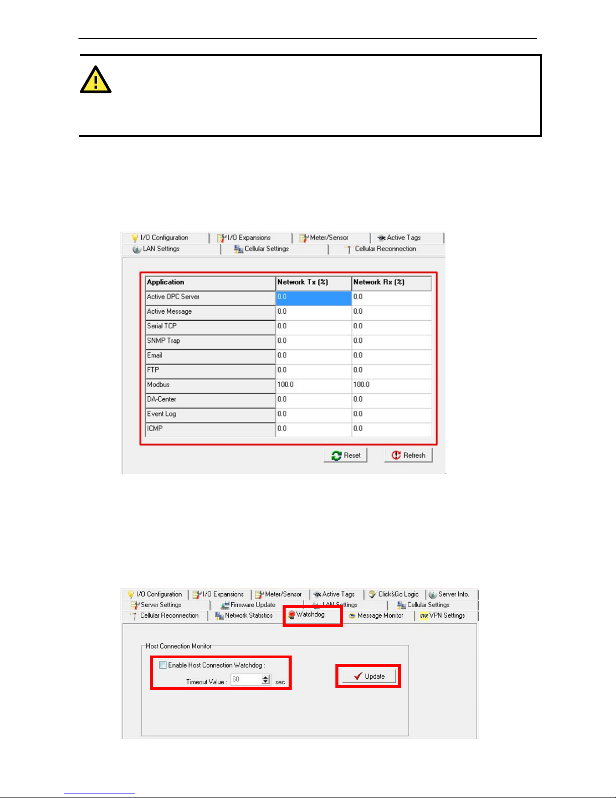
ioLogik W5300 Utility: ioAdmin
3-35
ATTENTION
Because t
here are major structural differences between firmware versions, you should upgrade from earlier
version
s to firmware V1.3 or above for the ioLogik W5312 series, and V1.5 or above for the ioLogik W5340
series
to reset all settings to the factory defaults. You should NOT perform the upgrade remotely over the
Internet.
Network Statistics
Network Statistics help monitor the usage of all applications’ network flow. The applications include Active OPC
server, active message server, serial TCP, SNMP trap, Email, FTP, Modbus, DA Center, Event Log, and ICMP.
The Network Statistics Page will help you understand the overall usage of the network.
Watchdog Panel
The Watchdog panel is available after you log in as administrator. When enabled, the Host Connection
Watchdog monitors the network connection. If the connection is lost for the specified Timeout Value, the
watchdog will display a warning and activate the Safe Status settings for each DO channel and event counter
channel. By default, the watchdog is disabled. To enable the watchdog, make sure that Enable Host
Connection Watchdog is checked, set the Timeout Value, and then click Update.
Page 62

ioLogik W5300 Utility: ioAdmin
3-36
After the watchdog is enabled, a
warning will be displayed on the
Watchdog Panel if the network
connection is lost.
After you restore the network
connection, click Clear Alarm to
reset the Watchdog and return to
normal operation.
Click&Go Logic Panel
The Click&Go Logic panel is
available after logging in as an
administrator. This is where the
ioLogik W5300 is configured.
With a set of rules (known as a
ruleset) defined through
Click&Go, the ioLogik can report
I/O status to a host as soon as
user-defined I/O conditions have
been met. Refer to Chapter 4
for more detailed information
on defining rules.
Changes on the Click&Go Logic panel are not effective until the ioLogik W5300 is restarted, as is true with
changes made on other panels. After logging back in as administrator and returning to the Click&Go Logic panel,
click Download to view the current ruleset. Click Run to activate the ruleset and Stop to deactivate it.
NOTE
Refer to the
following website to learn more about Click&Go: http://www.moxa.com/remote_io/ClicknGo.htm
ATTENTION
I/O channels used by Click&Go Logic
cannot be controlled externally using ioAdmin’s “Test” function,
other
Modbus/TCP master software, SCADA software, or SMS commands.
Page 63

4
4. Click&Go Logic
Click&Go Logic was developed by Moxa to provide an easy way to program your ioLogik W5300. In this chapter,
we explain how Click&Go Logic works and how to use it to deploy a remote I/O solution.
The following topics are covered in this chapter:
To Get a Quick Start…
Overview
Features
Click&Go Logic Basics
Working with the Rules
Click&Go Development Process
I/O Configuration
Configurable DIO Channel Mode Selection
Digital Input Mode Selection
Digital Output Mode Selection
Analog Input Mode Selection
Alias Configuration
Testing the I/O Channels
Defining Global Variables
Internal Register (Integer) Settings
Timer Settings
SNMP Trap Server
E-Mail Server
Active Message Server
SMS Phone Book
Working/Off Working Days
FTP Settings
Data Logging Profile List
Internal Register (Float) Settings
Working with Logic
Click&Go Logic Basics
IF…THEN/ELSE Conditionals
THEN/ELSE Actions
Activating the Rule-set
Upload, Restart, and Run
Rule-set Management Bar
Import/Export Configuration
Page 64

ioLogik W5300 Click&Go Logic
4-2
To Get a Quick Start…
Below, we highlight a series of entries to provide a quick review for readers already familiar with Click&Go.
I. Overview
• Software Overview
• Click&Go UI Basics
• Working with the Rules
II. Getting Started
Quickly set up your I/O and global variables so you can start working with rules:
• I/O configuration
• Defining Global Varibles
III. Start Working with the Logic
Learn the basics of Click&Go’s If-Then-Else Logic:
• If Logic
• Then and Else Logic
• Active Rule Set
• Import and Export Your Configuration
Overview
The ioLogik W5300 series system eliminates the need for host computers to continually poll I/O devices for
their status. Instead, the server itself is able to monitor the status of each I/O device and take the appropriate
action when the I/O status satisfies a user-defined condition. For example, the ioLogik could be configured to
send a TCP/UDP message only when the switch attached to DI-0 is turned on. This event-based structure
results in a much improved response time and a much reduced load on the host computer’s CPU and network
bandwidth.
The ioLogik W5300 supports Moxa’s Click&Go Logic. With Click&Go Logic, you can easily and intuitively
configure when and how I/O information is transmitted over the network. Simple IF-Then-Else statements
are used to specify conditions that are required for certain actions to take place. Up to three conditions and
three actions can be combined in a rule, and you can define up to 24 rules. Supported actions include sending
SNMP traps or TCP/UDP messages to up to 10 hosts at a time.
Click&Go Function Comparison Table by Product Line
Click&Go Function ioLogik E2000 ioLogik W5300
Peer-to-Peer Yes No
Remote Action Yes No
CGI Command Yes No
Trigger Logic
IF-Then-Else rule 24 rules 24 rules
Internal Register 24 24 + 28 float points
Timer 24 24
Schedule Yes Yes
Alarms
TCP/UDP Active Message Yes Yes, Unicode support
SNMP Traps Yes Yes
E-Mail Yes Yes, Unicode support
SMS No Yes, Unicode support
Page 65

ioLogik W5300 Click&Go Logic
4-3
Features
Click&Go Logic has the following key features:
• Easy local logic control using intuitive IF-Then-Else style construction.
• Up to 24 user-defined rules.
• Up to 3 I/O-based conditions and 3 DO or network actions per rule.
• Choice of email, TCP, UDP, SNMP trap, and SMS for active I/O messaging.
• Customizable message content with dynamic fields for time, date, IP address, and more.
• Up to 10 simultaneous IP destinations for TCP/UDP messaging.
• Internal register function for remote output control when Click&Go is running.
• Timer Delay function for timing events.
• Configurable interval for time-triggered events.
NOTE
In this chapter, all the descriptions are based on the ioAdmin 3.10. Be sure to use firmware V1.3 or above for
the ioLogik W5312 series, firmware V1.5 or above for the ioLogik W5340 series, and Active OPC Server V1.11
or above.
Click&Go Logic Basics
To use Click&Go Logic, start ioAdmin and log on as an ioLogik administrator on the Server Settings panel. Once
you are logged on, go to the Click&Go Logic panel. It should appear as below:
Click&Go Logic Panel
1. Global Variable: In this field, you can assign a Global Variable for the set of rules.
2. Logic Name: In this field, you can assign a name for the set of rules.
3. Rules List: In this area, each rule’s conditions, actions, and status are displayed.
4. Ruleset Management Bar: In this area, you manage the ruleset.
Page 66
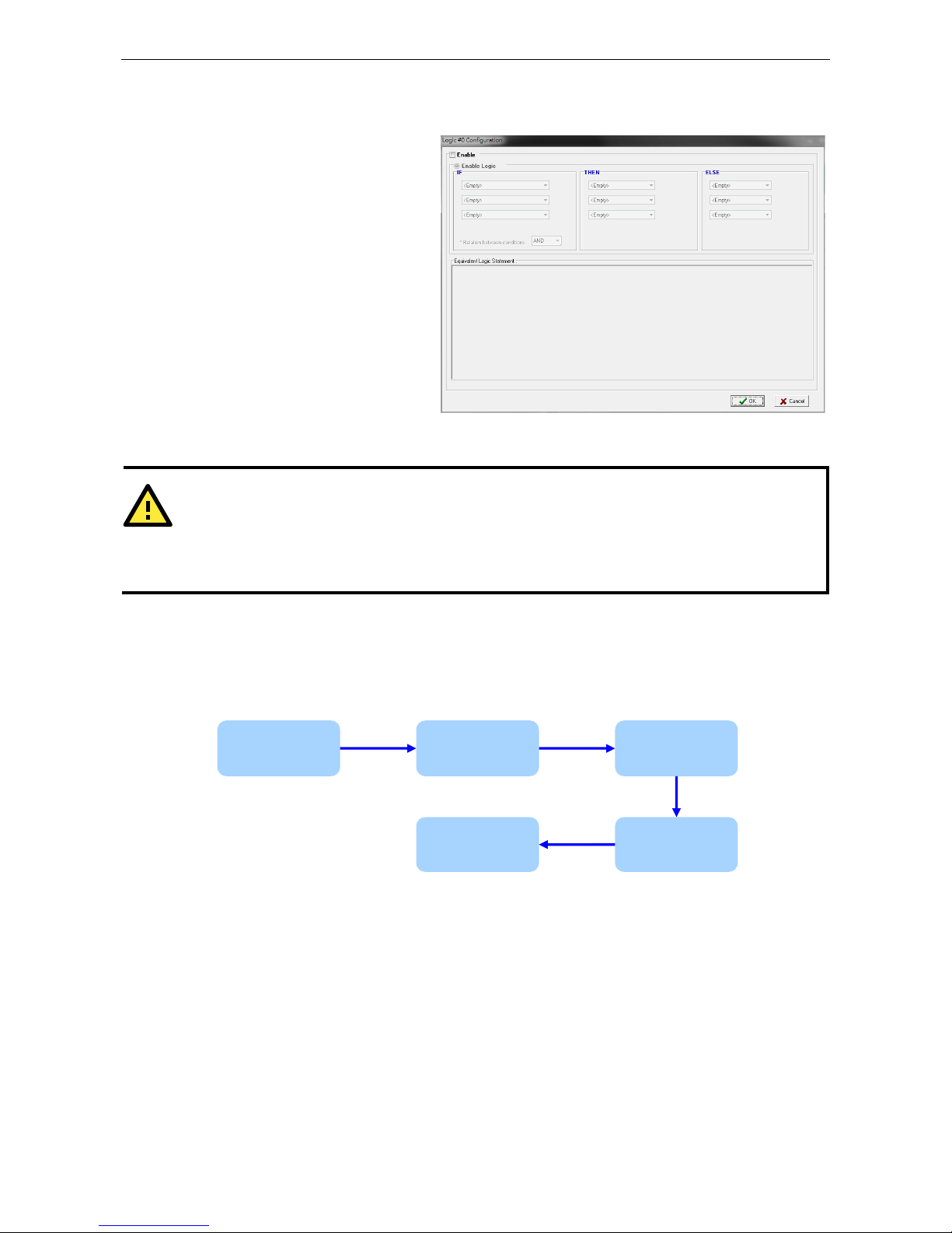
ioLogik W5300 Click&Go Logic
4-4
Working with the Rules
Rules are the building blocks of your
ioLogik W5300. With rules, you define the
exact trigger conditions for transmission
of I/O information as well as the content
and destination of that information. A
DO’s reaction can also be automated
through DI trigger conditions.
In the main screen, you will see a list of
the rules in the current rule set. Double
click on a rule to open that rule’s
configuration window, or double click on
an empty rule to start a new rule.
The Equivalent Logic Statement at the
bottom shows a real-time text-based
summary of the rule that you are defining, and provides a useful means of making sure that the rule is designed
as you intended.
ATTENTION
When configuring input and output control and response values,
you must select the unit of
measurement before entering a value
. If you select a unit of measurement after entering a value, the
value will not be retained. In addition, when an I/O channel is being used in a Click&Go Logic rule, the
channel’s range and units cannot be modified.
Click&Go Development Process
After searching and setting up the IP address of an ioLogik Ethernet I/O server, Click&Go logic can be
developed by following the procedures below:
I/O Configuration
ioLogik products are embedded with various types of I/O channels, and the mode of each input/output channel
must be configured before using the channels. Channels are divided into five categories: digital inputs, digital
outputs, analog inputs, analog outputs, and virtual channels.
Configurable DIO Channel Mode Selection
For models that support the configurable DIO channels, configure the specific DIO to DI or DO to meet the
requirements.
I/O
Configuration
Define Global
Variables
Work with
Logic
Activate
Rule-set
Import/Expor
t
Page 67

ioLogik W5300 Click&Go Logic
4-5
Model
Number of Configurable
DIO Channels
Mode Settings
Digital Input Digital Output
ioLogik
W5340-HSPA
8
ioLogik W5340 8
ioLogik W5312 4
When logged in as an administrator, double click on a channel in the I/O Configuration panel to configure
that channel’s settings. A window will open with configuration options for the channel. Each DIO channel will be
configured to act as either a DI or DO channel, according to the Power On Settings. To switch between DI and
DO channel operation, select the
desired mode in the I/O Direction
field under Power On Settings.
After clicking Apply, you will need to
restart the ioLogik for the new
setting to take effect.
ATTENTION
Switch
ing between DI and DO channel requires
restarting the ioLogik for the new setting to take effect. You
must restart the ioLogik b
efore proceeding with configuration or programming.
Digital Input Mode Selection
A DI channel can be set to DI or Event Counter mode. In DI mode, the channel connects to wet/dry contacts.
In Event Counter mode, the channel accepts limit or proximity switches and counts events according to the
ON/OFF status. When Lo to Hi is selected, the counter value increases when the attached switch is pushed.
When Hi to Lo is selected, the counter value increases when the switch is pushed and released.
Model
Number of Digital Input
Channels
Mode Settings
DI Event Counter
ioLogik W5340-HSPA 8
ioLogik W5340 8
ioLogik W5312 8 DIs+4 DIOs
When logged in as administrator, double click on a
channel in the I/O Configuration panel to
configure that channel’s settings. A window will
open with configuration options for that channel.
Each DI channel will be configured to act as either
a DI or Event Counter channel, according to the
Mode Settings. To switch between DI and Event
Counter channel operation, select the desired
mode under Mode Settings.
ATTENTION
On this
panel, be sure to select Start under Counter mode parameter on Power On Settings to
activate
the Event Counter channel.
Page 68

ioLogik W5300 Click&Go Logic
4-6
Digital Output Mode Selection
A DO channel can be set to DO or Pulse Output mode. The Relay Output behavior is the same as DO.
Model
Number of Digital
Output Channels
Mode Selection
DO Pulse Output
ioLogik W5340-HSPA 8 DIOs + 2 Relays
ioLogik W5340 8 DIOs + 2 Relays
ioLogik W5312 8 DOs + 4 DIOs
When logged in as an administrator, double
click on a channel on the I/O
Configuration panel to configure that
channel’s settings. A window will open with
configuration options for that channel. Each
DO channel will be configured to act as
either a DO or Pulse Output channel,
according to the Mode Settings. To switch
between DO and Pulse Output channel
operation, select the desired mode under
Mode Settings.
Analog Input Mode Selection
Analog input channels can use either voltage or current to transmit signals.
Model Number of Analog Input Channels
Mode Selection
Voltage Current
ioLogik W5340-HSPA
ioLogik W5340
4 ±5 V, ±10 V, 0-10 V 0 to 20 mA,
4 to 20 mA
When logged in as administrator, double click on
a channel on the I/O Configuration panel to
configure that channel’s settings. A window will
open with configuration options for that channel.
Each AI channel will be configured to measure
either voltage or current according to the Range
Settings.
Page 69

ioLogik W5300 Click&Go Logic
4-7
Alias Configuration
Alias Name helps users configure the alias
of a DI or DO channels and define the logic
level (0 or 1) for the ON/OFF status. The
Alias can be monitored by the ioAdmin utility,
or queried by using a user-defined program
based on the Moxa MXIO library or standard
Modbus/TCP protocols.
For Click&Go programming, the Alias Name
will display the user-defined name when the
specified channel is selected. For example,
although the fist DI channel is represented
by DI-0 in Click&Go, you can change the
Alias Name to Door_0 for easier recognition
when programming.
When logged in as administrator, double
click on a channel on the I/O
Configuration panel to configure that channel’s settings. A window will open with configuration options for
that channel. The Alias name of each input/output channel can be configured by selecting the Alias Name
panel.
ATTENTION
We st
rongly recommend configuring the alias name for the I/O channel being used before performing any
further configuration or programming.
Testing the I/O Channels
Each I/O channel can be tested and monitored individually. When logged in as administrator, double click on a
channel from the I/O Configuration panel to configure that channel’s settings. A window will open with
configuration options for the channel. Tests can be done by opening the channel’s configuration window and
selecting the Test panel.
The Test panel shows how a channel’s status affects, or is affected by, the attached device. For output channels,
you can set the on/off status, start and stop a pulse, or output a voltage or current. For input channels, you can
monitor the attached device’s on/off status, counter, or input voltage/current.
Page 70

ioLogik W5300 Click&Go Logic
4-8
Defining Global Variables
Global Variables include
Internal Register
Settings, Timer Settings,
SNMP Trap Server, E-Mail
Server, Active Message
Server and SMS Phone
Book. If these functions will
be used in a Click&Go V2
rule-set, the default
configuration must first be
set from the Global Variable
Menu Bar.
The following global
variables are only supported
by the ioLogik W5300:
SMS Phone Book,
Working/Off Working Day, FTP, Data Logging Profile List, and Internal Register (Float).
Internal Register (Integer) Settings
Internal Register (Integer) is a flag that can be used with the Click&Go logic internally or externally. The 24
sets of internal registers can be polled and controlled by SCADA software using standard Modbus/TCP format,
or implemented to redirect the result of one Click&Go logic to another.
The default value of an internal register is “0”.
Register Number Initial Value
Internal
Register
Reg-0 to Reg-23 *0 to 255
Timer Settings
The Timer function allows users to delay an action, trigger an action to run, or repeat an action. A timer is
activated by a change of the logic event. After the timed interval has expired, the output will be performed.
The 24 timers that can be implemented with Click&Go V2 logic have the default time interval set to “5 seconds”
in the “STOP” state. Be sure to configure the interval before using a timer.
With the default state set to “START” the timer will start when the Click&Go logic is activated.
Timer Number
Initial State Configuration
Timer Timer-0 to Timer-23 START, *STOP
Page 71

ioLogik W5300 Click&Go Logic
4-9
SNMP Trap Server
The ioLogik W5300 supports SNMP v2 (Simple
Network Management Protocol) to allow
monitoring of the network and I/O devices with
SNMP Network Management software. It is
useful for building automation and telecom
applications. Before monitoring the system
information of an ioLogik via SNMP trap, first
define a rule in Click &Go logic to update the
I/O status (up to 10 SNMP trap servers can be
defined).
E-Mail Server
The E-mail Server
configures the parameters of
the target e-mail servers and
the recipient e-mail addresses.
The Recipient Database
should contain a list of
available e-mail addresses for
your network environment.
The e-mail message defined
in the Click&Go logic will be
sent to all addresses listed in
the Receiver(s) list. To add
e-mail addresses to the
Available receiver(s) list,
enter the Name and Mail
Address and click the Add
finger icon to move addresses
to the Recipient Database;
use the Remove finger icon
to remove it.
Under Mail Server Settings, you must configure the address of the SMTP server with your username and
password. When using an FQDN (Fully Qualified Domain Name) address, such as ms.moxa.com, you must
specify the ioLogik’s DNS settings or check the Cellular Settings to see if the DNS settings were retrieved by the
cellular connection.
Page 72

ioLogik W5300 Click&Go Logic
4-10
Active Message Server
The Active Message Server
configures one or more
destination IP addresses of the
Message Servers that receive
event messages generated by
the Click&Go logic. The message
protocol (TCP or UDP) and the
message socket port must also
be configured.
The active message defined in
the Click&Go logic will be sent to
all addresses listed in the
Message Recipient List.
Message Port(TCP/UDP):
The Port the computer uses to communicate with the device; the default port for TCP/UDP is 9000
SMS Phone Book
The SMS Phone Book configures one or more
destination phone numbers that will receive SMS (Short
Message Servers) event messages generated by the
Click&Go logic. The SMS defined in the Click&Go logic will
be sent to all mobile phones listed in the Phone Book. A
total of 20 receivers can be configured in the phonebook.
Page 73
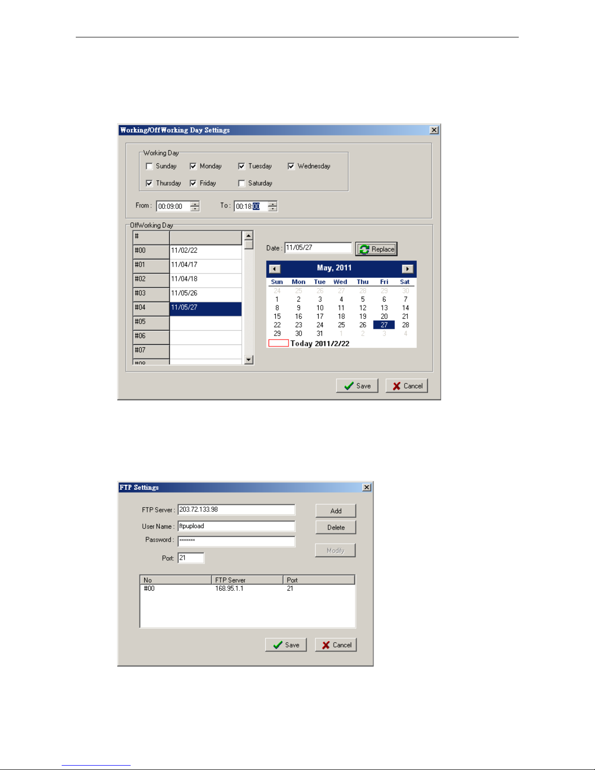
ioLogik W5300 Click&Go Logic
4-11
Working/Off Working Days
The Working/OffWorking Days defines the workweek days, hours, and off days to be used in the Click&Go
Schedule function. Specify the work days and hours first, double click to select the date in the calendar, and
then click the Replace button to update the selected entry of the off days.
FTP Settings
The FTP Settings dialog defines the target FTP server’s IP and user accounts to allow the ioLogik W5300 to
upload log files. Specify the FTP Server’s IP address and accounts and press the Add button to create a new
entry in the list.
Page 74

ioLogik W5300 Click&Go Logic
4-12
Data Logging Profile List
The Data Logging Profile List defines how to log the I/O data into the SD card. A total of 5 profiles can be
created, and multiple/duplicate channels can be included in different profiles.
Take the following steps to create a profile:
1. Click the New button to create a new profile.
2. Click Enable and specify a name for the profile. In addition, specify the Initial State and capacity of a log
file. If you select Start as the initial state, logging will start immediately once the profile is established. If
you select Stop, a Click&Go logic must be performed to start the logging.
Page 75

ioLogik W5300 Click&Go Logic
4-13
3. Define how to log the data by specifying the Logging Type. Users can choose to log when the I/O status
changes (On Change), to log periodically (Periodical), or by pre-configured schedule (Schedule).
The Schedule settings are extremely flexible and can log by day, week, or month. Specify the hours and
then click the Add button to add a setting of the schedule to the list.
Click Next to proceed.
4. Specify the channels to be logged. The percentage indicates the change of an analog channel when
choosing the On Change logging type. Specify the percentage for an analog channel before selecting the
channel in the right column.
Page 76

ioLogik W5300 Click&Go Logic
4-14
5. Click Finish.
6. Click Save.
Internal Register (Float) Settings
Internal Register(Float) can be used as an analog comparison (dynamic throughput setting) and flag with
the Click&Go logic internally or externally. The 28 sets of internal registers (float) can be polled and controlled
by SCADA software using the standard Modbus/TCP format, or implemented to redirect the result of one
Click&Go logic to another. The default value of an internal register is 0.
Register Number Initial Value
Internal Register
FloatReg-0 to FloatReg-27
0.000 (4-byte float point)
Page 77

ioLogik W5300 Click&Go Logic
4-15
Working with Logic
Click&Go Logic Basics
The Click&Go Logic panel is available after logging in as administrator. This is where Click&Go logic is
configured. With a set of rules (known as a rule-set) defined through Click&Go, the ioLogik can perform local
and remote I/O control, report I/O status, and actively send out messages, e-mails, or SNMP traps to a host as
soon as the user-defined I/O conditions have been met.
To use Click&Go Logic, start ioAdmin and log in as ioLogik administrator from the Server Settings panel. Once
you are logged in, go to the Click&Go Logic panel. The following screen should appear:
Click&Go Logic Panel
1. Global Variable: In this field, you can configure global variable rules.
2. Logic Name: In this field, you can assign a name to the set of rules.
3. Rule-set: In this area, each rule’s conditions, actions, and status are displayed.
4. Rule-set Management Bar: In this area, you manage the rule-set.
Rules are the building blocks of your ioLogik system. With rules, you define the exact trigger conditions for
transmission of I/O information as well as the content and destination of that information.
Click&Go Logic can be defined in the following ways:
Page 78

ioLogik W5300 Click&Go Logic
4-16
IF “A” THEN “B”, ELSE “C”
For one control logic rule, there are three “A’s” that can be configured. “A” refers to the IF conditions that
trigger an action. These three conditions can be operated by “AND” or “OR” logic. If “AND” logic is used, all
three conditions must be true to create a positive result. If “OR” logic is used, one or more true conditions must
be met to trigger the action.
A1 A2 A3
Result of
AND Logic
A1 A2
A3
Result of
OR Logic
0 0 0 0 0 0 0 0
0 0 1 0 0 0 1 1
0 1 0 0 0 1 0 1
0 1 1 0 0 1 1 1
1 0 0 1 1 0 0 1
1 0 1 1 1 0 1 1
1 1 0 1 0 0 0 1
1 1 1 1 1 1 1 1
The 24 rules are defined individually and are executed one by one in a loop. The 2nd rule can only be processed
after running the 1
st
rule, and the entire rule-set will start running from the beginning after the last rule is
processed.
You will see a list of the rules in the current rule-set on the main screen. Double Click on a rule to open that
rule’s configuration window, as shown in the following figure, or double click on an empty rule to start a new
rule.
Page 79

ioLogik W5300 Click&Go Logic
4-17
Under Relation between conditions, select AND to specify that all conditions must be satisfied for the
actions to take place; select OR to specify that any one of the conditions can be satisfied for the actions to take
place. The Equivalent Logic Statement at the bottom shows a real-time text-based summary of the rule that
you are defining. It provides a useful way to make sure the rule is designed as you intended.
IF…THEN/ELSE Conditionals
IF statements are trigger THEN/ELSE actions. Under the IF column, you can set up to 3 conditions that must
be satisfied (when more than one condition is defined, AND or OR determinants are used to complete the logic),
and which will, according to the inputs, determine whether actions under the THEN or ELSE column will take
effect. For example, an alarm can be activated when a door is opened. Use the pull downs to specify the
conditions and units of measurement (e.g., DI-0=OFF).
IF conditions may be defined as follows:
IF Conditions Operators Remark
DI ON, OFF, ON to OFF, OFF to ON, Change DI-x represents the channel number
Counter =, >, <, >=, <=, Change Counter-x represents the channel number.
Max Counter Value: 4,294,967,295
AI =, >, <, >=, <= AI-x represents the number of the channel.
Max Value: Depends on the analog modes
or the result of scaling. Internal
Register(Float) can be used as the
comparison or throughput setting
controlled by remote SCADA or a
Modbus/TCP program.
Relay =, >, <, >=, <= CurRelayCNT-x represents the current relay
counts for the channel.
Max Value: 4,294,967,295
Internal Register = Reg-x represents the number of the
internal
register.
x = 00 to 23 / Trigger Value: 0 to 255
Timer TIMEOUT Timer-x, x = 00 to 23
Max value: 4,294,967,295 seconds
Schedule Time, Range and Recurrence
Expansion
Module
Connection
Failure
0, 1
Virtual Channel =, >, <, >=, <= VC-x represents the channel number
System Start up N/A Activate when the system is starting up at
System Start
Page 80

ioLogik W5300 Click&Go Logic
4-18
NOTE
The following IF Conditions are only supported
by the ioLogik W5300: Expansion Module Connection
Failure
, Virtual Channel, and System Start-up.
DI: Digital Input
DI refers to the status of a
digital input channel. Edge
detection may be used to
further define the electrical
requirements for signaling. For
example, the condition
DI-0=OFF is satisfied for as
long as DI-0 remains off. The
condition DI-0=ON to OFF,
however, is only satisfied the
instant the DI-0 turns off. The
transition of the status change
can also be handled using the
Change operator, so that actions are triggered both for ON-to-OFF and OFF-to-ON transitions.
Scroll to select DI and click on the property ( ) button to enter the DI Settings window.
Counter
Counter refers to the counts of an Event Counter channel. The counts are stored in the ioLogik internally.
Specifying the counts with a
proper operator will lead to
triggering the action. For
example, if 10 items should be
packed in a box, the Counter-x
should be reset every 10
counts (Counter-1=10).
Select the IF condition to
Counter and click on the
property button ( ) to
enter the Counter Settings
window.
AI: Analog Input
AI refers to the readings of
an analog input channel. An
analog input value is specified
to trigger an action. Units of
the value are defined by the
selected analog modes
(voltage or current), or the
scaling results. For example,
AI-0 > 15 mA represents
the high level of a water tank.
Page 81

ioLogik W5300 Click&Go Logic
4-19
Virtual Channel
VC refers to the readings of a statistics channel.
The value can be recorded in the data log file, or
specified to trigger an action. Units for the value
are determined by the user defined unit, or the
scaling results. For example, VC-0 > 15 ml/s
represents a water flow amount greater than 15
ml/s.
Relay (Counter)
Relay refers to the current
counts of the relay usage.
Checking the current counts of a
relay will produce the action. For
example, if the average
life-cycle of a relay is 25,000
times, an alarm e-mail may be
generated when the counter
reaches 20,000 times
(CurRelayCNT-0 > 20000) to
report the need for a
replacement.
Internal Register (Integer)
Internal Register (Integer)
represents a status flag to link
the status of the first logic to
the second one. It is used most
often with the Timer function,
or to combine other input
statuses together. The Internal
Register function also allows a
PC to control the ioLogik’s local
output when the remote output
is controlled by a Click&Go log
(e.g., digital output, active
message, e-mail, or SNMP
Trap). Select the IF condition
for the Internal Register and
click on the property button
( ) to enter the Set
Internal Register window.
In the above figure, the “Used in:” column indicates that this Internal Register is also used with Rule-0, which
helps the user identify the relationship between the rules. Also, the Set Internal Register button ( ) will help
to define the default values of all Internal Registers.
NOTE
Internal Registers can be controlled by Modbus/TCP protocol. Refer to the
appendix f
or the address list for all
Internal Registers.
Page 82

ioLogik W5300 Click&Go Logic
4-20
Timer
The Timer function can be used to control the timing of a logic rule in the IF conditions. “TIMEOUT” is the only
operator here. For example, you can delay the triggering of an action or repeat an action periodically. Select the
IF condition for Timer and click on the property button ( ) to enter the Timer Settings window.
In the above figure, the “Used in:” column indicates this Timer is also used in Rule-0, which helps the user
indentify the relationship between rules. In addition, the Set Timer button ( ) will help define the default
value for the Timer.
Schedule
The Schedule function allows users to set a starting point or time period for a task. For example, the Schedule
function could be used if a pump needs to start at 9:00 PM and stop at 11:00 PM every Monday, Wednesday,
and Friday.
Select the IF condition for Schedule and click on the property button ( ) to enter the setting window. For
recurrent actions, select the Recurrence checkbox and select the relevant weekdays. If a time period needs to
be defined, specify the stop date in the range column.
Page 83
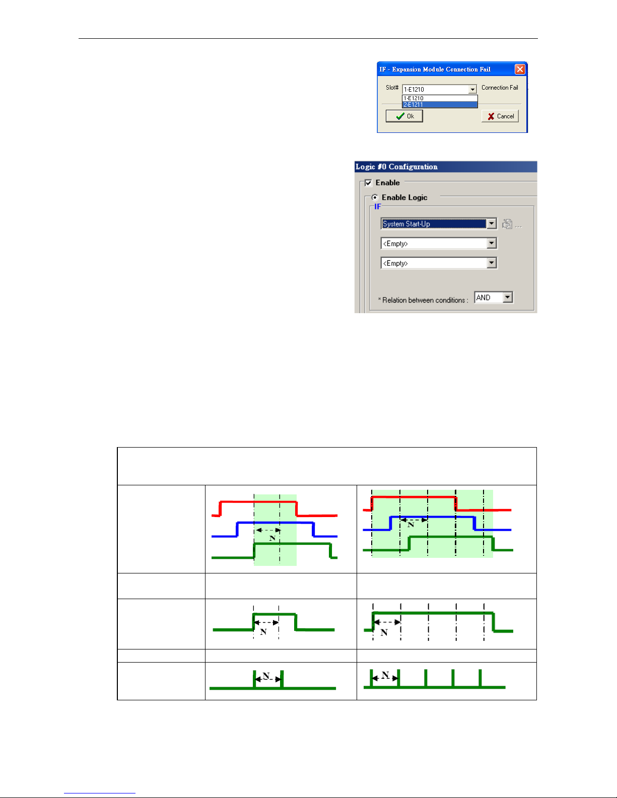
ioLogik W5300 Click&Go Logic
4-21
Expansion Module Connection Fail
The slot you select in the Expansion Module Connection Fail
window will monitor while Click&Go is running. The monitored
target is specified for these expansion modules.
System Start-up
Click&Go logic provides the IF condition to perform an action,
such as triggering the local output or SMS alarm to indicate
that the system is restarting.
More Information about Repeat Interval vs. Edge Detection
Combining the Timer function with other IF conditions allows actions to be repeated when the specified logic is
sustained over a period of time. However, if a condition is based on edge detection (i.e., ON to OFF or OFF to
ON), it can only be triggered once.
The following scenarios illustrate how edge detection affects the Timer = N sec. In each diagram, the statuses
of three sensors are shown over a period of time, with a high signal corresponding to a “true” condition. The
green shaded area shows the duration of time that the IF conditions have been met.
No Edge Detection
In this scenario, the rule checks each sensor for “on” status, so edge detection is not involv
ed. As long as the
sensors remain on, the required conditions are satisfied, and the THEN actions will repeat at interval N.
DI-0 = ON
DI-1 = ON
DI-2 = ON
Relation between
conditions
AND OR
“IF” conditions
satisfied
Repeat interval “Timer = N sec” “Timer = N sec”
“THEN” action
triggered
Page 84

ioLogik W5300 Click&Go Logic
4-22
Edge Detection for All Conditions
In this scenario, the rule checks each sensor for a change from “off” to “on” status, meaning only edge
detection conditions are used. As soon as a sensor changes from “off” to “on”, the condition is satisfied, but
only for that instant. Right after that instant, the condition is no longer satisfied because it is no longer
changing from “off” to “on”. The repeat interval will have no effect, since edge conditions cannot be sustained
over a period of time.
DI-0 = OFF to ON
DI-1 = OFF to ON
DI-2 = OFF to ON
Relation between
conditions
AND OR
“IF” conditions
satisfied
Repeat interval N/A N/A
“THEN” action
triggered
Edge Detection for Two Conditions
In this scenario, the rule checks DI-0 and DI-1 for a change in status and DI-2 for status only. The repeat
interval will not have an effect if the AND relationship is used, because the two edge conditions can never be
sustained over a length of time. With the OR relationship, the IF conditions will be satisfied as long as DI-
2 is
“on”, and the THEN actions will be triggered over interval N.
DI-0 = OFF to ON
DI-1 = OFF to ON
DI-2 = ON
Relation between
conditions
AND OR
“IF” conditions
satisfied
Repeat interval N/A N/A
“THEN” action
triggered
Edge Detection for One Condition
In this scenario, the rule checks DI-0 for a change in status and DI-1 and DI-2 for status only. The repeat
interval will not have an effect if the AND relationship is used, because the edge condition for DI-0 can never
be sustained over a length of time. With the OR relationship, the IF conditions will be satisfied as long as DI-
1
or DI-2 is “on”, and the THEN actions will be triggered over interval N.
DI-0 = OFF to ON
DI-1 = ON
DI-2 = ON
Page 85

ioLogik W5300 Click&Go Logic
4-23
Relation between
conditions
AND OR
“IF” conditions
satisfied
Repeat interval N/A “Timer = N sec”
“THEN” action
triggered
THEN/ELSE Actions
Under the THEN column, you can specify up to 3 actions that will be performed when the IF conditions are
satisfied. 3 actions under the ELSE column will also be performed when the IF is NOT satisfied. Possible
actions include changing the status of a DO channel, starting or stopping an Event Counter, or sending a
message by SNMP trap, TCP, UDP, or e-mail.
If Conditions
Result of
AND Logic
Trigger of
Then Actions
Trigger of
ELSE Actions
A1
A2
A3
0 0 0 0 NO YES
0 0 1 0 NO
YES
0 1 0 0 NO YES
0 1 1 0 NO YES
1 0 0 0 NO YES
1 0 1 0 NO YES
1 1 0 0 NO
YES
1 1 1 1 YES YES
If Conditions
Result of
OR Logic
Trigger of
Then Actions
Trigger of
ELSE Actions
A1 A2 A3
0 0 0 0 NO
YES
0 0 1 1 YES NO
0 1 0 1 YES NO
0 1 1 1 YES NO
1 0 0 1 YES NO
1 0 1 1 YES
NO
1 1 0 1 YES NO
1 1 1 1 YES NO
Page 86

ioLogik W5300 Click&Go Logic
4-24
THEN/ELSE actions can be specified as follows:
THEN/ELSE Actions Operators Remark
Counter RESET Counter-x represents the number of the Event Counter channel
DO ON, OFF DO-[X] represents the number of the channel.
Pulse Output STOP, START Pulse Output-[X] represents the number of the channel
AO For ioLogik E1241 expansion
Relay Output RESET ResetCNT-[X] represents the number of the relay channel.
Internal Register Reg-x represents the number of the internal register.
x = 00 to 23 / Trigger Value: 0 to 255
Timer STOP, START,
RESTART
Timer-x, x = 00 to 23
Max value: 4,294,967,295 seconds
SNMP Trap I/O Status Bindings: 3 sets
Active Message ID / Source IP Unicode supported
e-Mail Create the contents of the email
Short Message Service Select recipients from the phone book, define the content, and
configure the escalation
Data Log Start/Stop Start, Stop Select which profile to start or stop
FTP Service Select which profile and FTP server to upload the log file
NOTE
The following THEN Actions are only supported by the ioLogik W5300: Short Message Service, Data Log
Start/Stop
, and FTP Service.
Counter
In this THEN/ELSE action, the
only operator for the Counter
function is “RESET”, which clears
the counts of an Event Counter
channel. This function is often
used in a charging system to
clear the readings of a meter.
Select the THEN/ELSE action to
Counter and click on the
property button ( ) to enter
the Counter Settings window.
DO
DO refers to the action of
controlling the local digital
output channels that react to
the IF conditions. Select the
THEN/ELSE action to DO and
click on the property button
( ) to enter the DO Settings
window.
NOTE
A Relay output channel is also referred to as a DO channel in the THEN/ELSE action fields.
Page 87

ioLogik W5300 Click&Go Logic
4-25
Pulse Output
Pulse Output starts or stops a
pulse. It is usually used to create
the flash for an alarm light.
Select the THEN/ELSE action to
Pulse Output and click on the
property button ( ) to enter
the Pulse Output Settings
window.
AO
Analog Output (AO) refers to
the action of controlling the local
Analog Output channels that
react to the IF conditions. Select
the THEN/ELSE action to AO and
click on the property button
( ) to enter the AO Settings
window.
Relay (Counts)
In the THEN/ELSE action, Relay
refers to the current counts
specifying how many times a
relay has been triggered. The
counts are stored internally and
can be cleared. “RESET” is the
only operator. Select the
THEN/ELSE action to Relay and
click on the property button
( ) to enter the Relay Settings
window.
Page 88
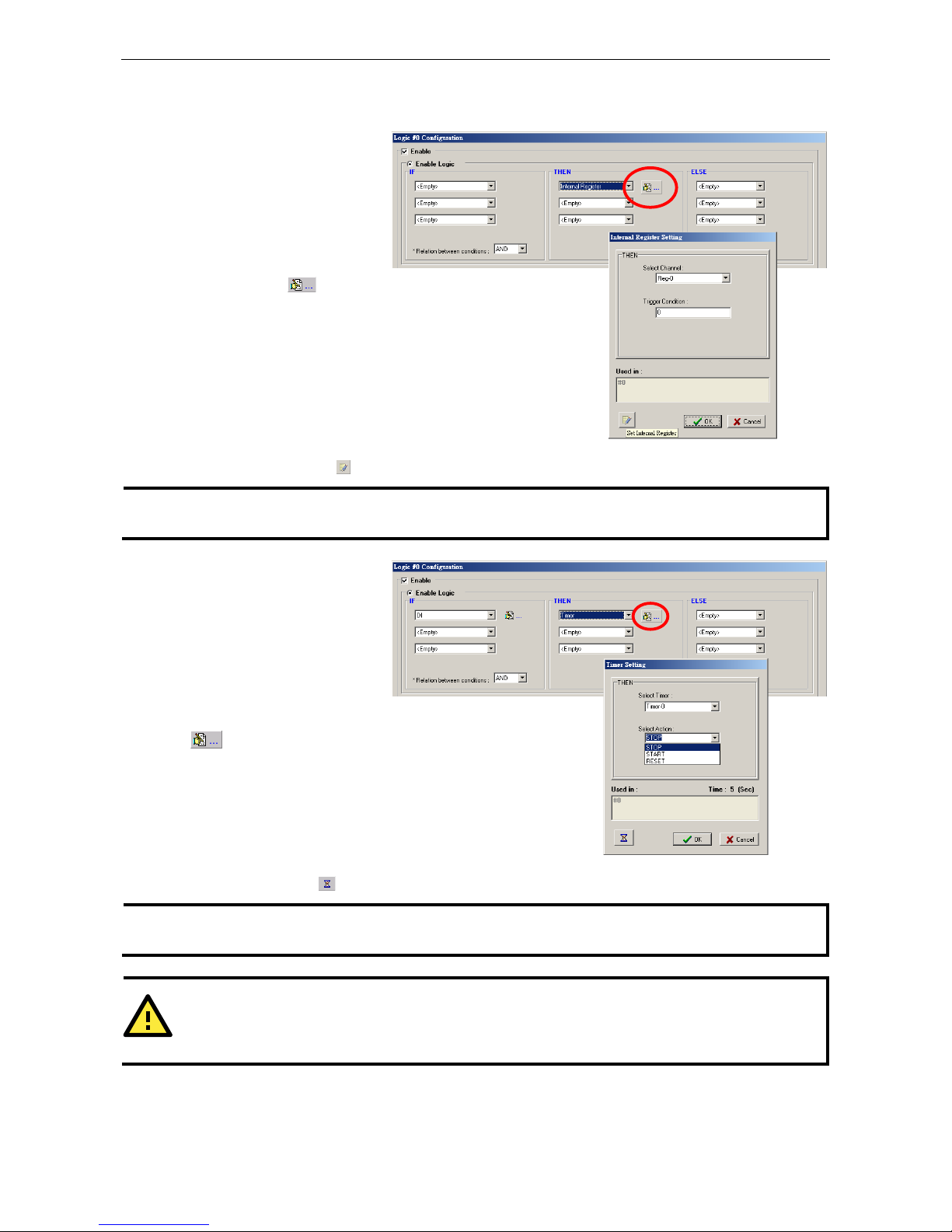
ioLogik W5300 Click&Go Logic
4-26
Internal Register (Integer)
Internal Register (Integer)
represents a status flag to link
the status of the first logic to the
second one by specifying other
actions in the THEN/ELSE fields.
Values from 0 to 255 can be used
here. Select the THEN/ELSE
action for Timer and click on the
property button ( ) to enter
the Internal Register Settings
window.
In the above figure, the “Used in:”
column indicates that this
Internal Register is also used in
Rule-0, which helps the user
identify the relationship between
the rules. In addition, the Set
Internal Register button ( ) can be used to define the default values of all registers.
NOTE
Internal Register can be controlled by Modbus/TCP protocol. Refer to the appendix for the address list of all
Internal Registers.
Timer
The Timer function can be used
to control the time settings of a
logic rule. Actions such as
START, STOP, and RESTART
can be configured here.
Select the IF condition for Timer
and click on the property button
( ) to enter the Timer
Settings window.
In the above figure, the “Used in:”
column indicates this Timer is
also used in Rule-0, which helps
the user identify the relationship
between the rules. In addition,
the Set Timer button ( ) can be used to define the default value of the Timer.
NOTE
The “STOP” operator stops the timer and returns to “0”, and the “RESTART” operator clears and restarts the
timer.
ATTENTION
The
STOP or RESTART operator should always be used to reset or to restart the timer. If you do not use
these
operators,
the Timer function can only be triggered once.
Page 89

ioLogik W5300 Click&Go Logic
4-27
SNMP Trap
The SNMP Trap function sends
an SNMP trap to one or more IP
destinations. The trap number
can be any number between 1
and 20. (You may need to
consult with your network
administrator to determine how
trap numbers will be used and
defined on your network.) Select
the THEN/ELSE action for SNMP
Trap and click the property
button ( ) to enter the SNMP
Settings window. You can also
bind the status of up to three I/O
channels within each trap. Click the Set SNMP button ( ) to specify up to 10 recipients for the SNMP trap.
Active Message
In response to a proper IF
condition, the Active Message
function sends a customized
message to one or more IP
destinations by TCP or UDP
packets. Select the THEN/ELSE
action for Active Message and
then click the property button
( ) to enter the Message
Content Settings window. Enter
your desired message in the
Message Content column.
Dynamic fields such as time,
date, IP address, and I/O status
can be inserted in your message by clicking Keyword Lookup. Messages are sent in ASCII by default, but can
be sent in HEX by selecting the “Send as HEX (separated by “,”)” checkbox.
Click the Set Active Message button ( ) to configure the default parameters such as the messaging protocol
(TCP or UDP), socket port (9000 by default), and the up to 10 target message servers.
Active Messages can be received by a program using standard sockets, Moxa MXIO library, or ioAdmin’s
Message Monitor, as shown in the following screen shot:
When sending a message in HEX, each HEX value must be separated by commas. View the incoming message
on the Message Monitor panel and select the HEX checkbox. Note that certain numbers are control characters
that will not show up in the Message Monitor. When sending a unicode message, the UCS2 checkbox must be
selected. View incoming messages on the Message Monitor panel and select the UCS2 checkbox. Note that
Page 90

ioLogik W5300 Click&Go Logic
4-28
certain numbers are control characters that will not show up on the Message Monitor panel. The maximum
number of characters is 200.
Email
The E-mail function sends a customizable e-mail to one or more mail boxes or Blackberry devices. Select the
THEN/ELSE action to e-mail and click the property button ( ) to enter the Mail Settings window.
After entering the subject of an e-mail, enter the message in the Mail Content area. Dynamic fields such as
time, date, IP address, and I/O status can be inserted in your message by clicking Keyword Lookup.
NOTE
Content in the same logic entry can be sent by either Active Message or e-mail, in which case the content of
the messages
will be the same. If you would like to send an Active Message and e-
mail based on the same
event but with different content, you will need to use two separate logic entries—one for the Active Message
and one for the e
-mail.
SMTP server information including username/password, and the recipient database can be configured by
clicking the Set Mail Address button ( ). Click the finger icon ( ) to move the selected address from
the Recipient Database to the Recipient List.
To manually add e-mail addresses to the Recipient Database, enter the Name and Mail Address and click Add.
Once the address has been added to the Recipient Database, use the finger icons to move it to or from the
Recipient List. Select Attach data log to specify that the log profile and period will be attached to the email.
Set Hours to 24 if you would like to receive all logs generated in the past 24 hours.
Page 91

ioLogik W5300 Click&Go Logic
4-29
Short Message Service
The Short Message Service function allows the user to configure the SMS in detail, including selecting
recipients from the phone book, defining the escalation and acknowledgements, and defining the content of the
SMS. If you select Send every__sec, the SMS will be sent to all the recipients at the same time; if you select
SMS Escalation, the SMS will be sent out in the sequence listed in the recipient list, and using the timeout
interval. A recipient will stop receiving the SMS alarm when the preset maximum repeat times is reached, or
when one receiver acknowledges receiving the SMS.
NOTE
Send every
means to send the SMS to all the recipients; SMS Escalation will send SMS to the recipients
sequentially and wait for the response (acknowledgement).
Data Log Start/Stop
The Data Log Start/Stop function provides the
capability to start or stop logging based on a specific
event (IF Conditions), such as to start logging when
the pressure (AI) reaches the maximum limit and to
stop logging when it returns to normal.
Page 92

ioLogik W5300 Click&Go Logic
4-30
FTP Service
The FTP Service function provides upload service for
data log files stored on the SD card. Combining this
function with Schedule or Timer in the IF condition will
create periodical or scheduled uploads of the log file.
Profile: Select a pre-configured FTP server.
Hours: The ioLogik W5300 will send all the log files
containing all the entries within this specified
time period.
Send Every: The datalogging file will be sent every
this number of seconds.
The following diagram gives an example. Log_01 to
Log_05 were created by the same profile. If configuring
the Hours to 24, the ioLogik will upload the entire
Log_01, Log_02, and Current Log_03. In the Next 24 hrs, the ioLogik will upload the entire Log_03, Log_04,
and Current Log_05. On the FTP Server, the Current Log_03 will be overwritten by the entire Log_03 when an
additional 24 hrs has passed.
Activating the Rule-set
Upload, Restart, and Run
The rules that are displayed on the Click&Go Logic panel include the current rule-set, which acts as the brain of
your ioLogik system. The rule-set must be activated as follows for the ioLogik to commence local control
operation:
1. The rule-set must first be downloaded from ioAdmin to the ioLogik. To download the rule-set, click Upload
to ioLogik from the Rule-set Management bar.
2. After the rule-set has been downloaded, ioAdmin will prompt to
restart the ioLogik automatically after clicking “yes” to confirm.
Page 93

ioLogik W5300 Click&Go Logic
4-31
Do not use the reset button, since doing so will load all factory defaults and erase your rule-set from
memory.
3. After the ioLogik has been restarted, the rule-set must be activated. Log in to ioAdmin as administrator, go
to the Click&Go Logic panel and click Run in the Rule-set Management bar. The rules in the rule-set will now
be active.
When the rule-set has been activated, it will remain active even when the ioLogik is disconnected from the host
computer or from the network. If the ioLogik is turned off, cellular I/O operations will resume when it is turned
back on, allowing you to use the ioLogik W5300 for PC-independent automation.
Rule-set Management Bar
When the rule-set has been activated from the Click&Go panel it will remain active even when the ioLogik is
disconnected from the host computer or from the network. If the ioLogik is turned off, cellular I/O operations
will resume when it is turned back on, allowing you to use the ioLogik W5300 for PC-independent automation.
• Clear: Erases the rule-set in both ioAdmin and the ioLogik W5300 series.
• Retrieve: Copies the rule-set from the ioLogik W5300 into ioAdmin.
• Upload to ioLogik: Copies the rule-set from ioAdmin to the ioLogik W5300.
• Run: Activates the rule-set that the ioLogik booted up with.
• Stop: De-activates the Click&Go rule-set and returns the ioLogik to normal, passive operation.
Import/Export Configuration
The ioLogik’s system configuration, including the current Click&Go rule-set, can be imported and exported. As
you make changes to a rule-set, you can export the system configuration in order to save that rule-set. Details
can be found in Chapter 2.
Log in as ioAdmin administrator from the Server Settings panel. You must log in as administrator to gain
access to the ioLogik’s configuration options. If a password has not been configured, simply click Login and
leave the Password entry field blank.
NOTE
Since
there are major structural changes
between firmware versions, configuration files generated by firmware
versions preceding V1.2 (included) for the ioLogik W5312 series, and firmware V1.4 (included) for the ioLogik
W5340 series, cannot be imported to the lates
t version of the firmware.
Page 94

5
5. Planning and Assistance
In this chapter, we will provide variety of real-life scenarios to help explain to you how to use the ioLogik W5300
to configure your system.
The following topics are covered in this chapter:
Known Issues of Cellular Monitoring Systems
Active OPC Server with a Static IP Address
Cellular Remote I/O Architecture
Using ioAdmin to Perform Simple Data Monitoring from a Remote Site
Expanding Input/Output Channels
Using Modbus/TCP Protocol with Your Program
Using Counter to Get Meter Readings and Statistics
Record your I/O Data in the Data Log File
Connecting a Modbus/RTU Serial Device Attached to the ioLogik over a Cellular Network
Connecting to a SCADA System
Updating Serial Tags to SCADA System with Active OPC Server over a Cellular Network
Handling Front-End Events and Alarms
SMS Escalation and Acknowledgement
SMS Commands for Monitoring and Control
Enabling the Power Saving Function and Secure Wake on Call
Enabling Ethernet and Cellular Redundancy
Page 95

ioLogik W5300 Planning and Assistance
5-2
Known Issues of Cellular Monitoring Systems
Cellular technology is well-suited for remote monitoring and alarm systems that cover a wide area, such as
pipeline monitoring of public water supplies or natural gas systems. Using cellular technology to implement a
remote monitoring system can save development, deployment, and maintenance time.
However, problems such as dynamic IPs, low bandwidth, and unexpected disconnections must be overcome for
the cellular monitoring system to achieve greater stability.
Known Issue 1: Dynamic or Private IP over a Cellular Network
Although cellular technology can make device communication easier, cellular networks were not designed for
industrial devices, but for mobile phones. Since mobile phones only need a temporary IP to connect to the
Internet, cell phones get a different temporary IP each time the mobile phone accesses the Internet. This is
referred to as the Dynamic IP issue. Most telecom service providers assign temporary IPs when a mobile phone
requests access to the Internet. A remote monitoring system using a cellular communications ioLogik W5300
should request a permanent IP to ensure stable bidirectional communications. For this reason, you may need
to apply for a special data plan from the service providers or the mobile virtual network providers (MVNOs).
As opposed to using the so-called “pull” or “passive” architecture, Moxa’s ioLogik W5300 utilizes active edge
communications, which works with the powerful cellular device management middleware, Active OPC Server.
Active OPC Server runs on a central network computer that uses a static IP. Even if the cellular I/O
units work in a dynamic or private IP environment with a general data plan that is for a mobile phone, since the
ioLogik W5300 contacts the Active OPC Server (and not the other way around), once a connection is
established the two sides of the connection can proceed with bi-directional communication. In addition, the
built-in front-end intelligence called Click&Go control logic enables the ioLogik to report its I/O status, and send
alarms and log data actively. Centralized software such as a SCADA system is now able to leverage this
technology by connecting the Active OPC Server using Modbus/TCP or OPC Client Drivers instead of connecting
to the remote ioLogik's IP address directly.
Known Issue 2: Low Bandwidth and slow response time
Cellular networks provide only low bandwidth transmission compared with wired CAT-5 Ethernet networks.
Generally speaking, the response time of the GPRS network is about 4 to 10 seconds, and 1 to 3 seconds for
3G/HSPA networks.
This means that the latency of data for one round trip is much slower than a millisecond level Ethernet network,
resulting in system overload or shutdown when a large number of remote sites and large amount of information
need to be exchanged. A better approach is to use an “active” architecture such as the ioLogik, and the Active
OPC Server to reduce traffic and improve response time and decrease the use of the bandwidth.
Another factor that could cause unexpected disconnection is the cellular signal strength. In some places,
several communication channels could exist simultaneously, with each device accessing a different channel and
using a different signal strength. This kind of random signal strength could result in unexpected disconnection.
SMS (short messages) will not respond in time as expected, especially when using a data plan that is only for
data transmission or at specific times, such the end of the year, when traffic volume is much higher.
Known Issue 3: Unexpected Disconnection from Cellular Networks (Carriers)
Although cellular network transmissions are charged by number of packets and not connection time, most
vendors still refer to their service as “Always On.” However, a better description might be “always accessible”
since in reality, cellular carriers optimize their IP resources, time slots, and the base station capacity by
disconnecting connections that have been idle for a certain period of time. During this period, the mobile
devices will not be aware of the disconnection, and this lapse in the actual connection could introduce a certain
amount of unreliability in your remote monitoring and alarm system. If using “Always On” to keep your
connection alive is not stable enough for your purposes, you must configure additional “Cellular Reconnection”
settings to prevent being kicked off the network accidentally or without notification. See Chapter 4 for detailed
settings.
Page 96

ioLogik W5300 Planning and Assistance
5-3
Known Issue 4: Large Power Consumption when Attached to Base Stations
There will be a peak power usage when attaching to base stations (900 mA @ 12 VDC). Although the ioLogik
uses a low amount of power during normal usage (3-4 watts), we still recommend using a power supply that
is greater than 5 watts.
Active OPC Server with a Static IP Address
Configuring an ioLogik W5300 for use with an Active OPC host using a static IP address will ensure that the
ioLogik W5300 works properly in any of the following environments:
1. Virtual Private Network
A VPN (Virtual Private Network) is a service that groups all related devices into one network, but users need
to purchase cellular on-line services and apply for VPN membership. When the Cellular device dials up, it
will get a private static IP assigned by the telecom service provider (Carrier or MVNO). The private IP is on
the same network segment as the host. The host and devices can communicate bi-directionally using a
polling architecture. Most telecom service providers will not offer small volume service packages to
enterprise clients. A mobile virtual network operator (MVNO) is a company that provides cellular services
but does not have its own licensed frequency allocation of the radio spectrum, and does not necessarily
have the infrastructure needed to provide mobile telephone services. An MVNO subscribes to several
cellular services and then rents the services out to customers who only need a small quantity of IP service.
Normally, the MVNO also builds up a VPN server to separate their groups, and in effect provide the same
services provided by a VPN.
2. Network with Public Static IP Devices
A Public Static IP can be accessed anywhere and anytime, such as over the Internet. Although most carriers
use private dynamic IPs for mobile phones, some carriers will provide Public Static IPs for specific
applications. The downside of Public Static IP service is that it comes at a much higher price. Some telecom
service providers can assign a fixed IP to one specific SIM card. While all I/O devices have their own fixed
IP address, the entire system will run as a traditional monitoring system with physical wires. This solution
has the benefit exhibiting the same behavior as a wired solution. However, not all telecom service providers
offer this kind of service, and those that do offer it at a relatively high cost.
3. New Cellular Network with Active Architecture
A new type of cellular network based on push technology is now available. This type of service requires a
host PC with a public static IP, allowing all remote cellular devices to connect to the host PC, regardless of
whether or not the device has a public or private IP. The Active OPC Server software running on a PC with
a static IP is required to update the devices’ IP and the fixed device name. After connecting to the cellular
network, all operations can follow the original infrastructure of the mobile phone provider. Moxa’s ioLogik
W5000 series cellular remote I/O units are based on push technology with Active OPC Server. Active OPC
Server, which runs on a PC with static IP, will receive and register the device’s IP and create a connection
while the ioLogik W5300 is on line. Once the connection has been created, bi-directional communication can
ensue. The built-in front-end intelligence, Click&Go logic, enables the ioLogik to report its I/O status, alarms,
and log data actively.
Page 97

ioLogik W5300 Planning and Assistance
5-4
NOTE
If the Active OPC Server is installed in the DMZ or even the LAN, be sure to configure the router or firewall
settings to allow and redirect those necessary TCP
ports such 9300, 9900, 9500,
and 502 for remote access
from the io
Logik W5300. See Appendix F for details.
Cellular Remote I/O Architecture
The following diagram illustrates the overall architecture of the ioLogik 5300 series cellular remote I/O device.
The ioLogik 5300 supports remote monitoring, and you can configure the machine via ioAdmin and connect to
a SCADA system through an OPC client/server or Modbus/TCP. You can push datalog files to the FTP server,
and connect field serial devices through a serial tunnel. In addition, the ioLogik W5300 supports event alarms
by email, SNMP Trap, and SMS.
In the following sections, we illustrate how to set up an environment for the ioLogik W5300.
Using ioAdmin to Perform Simple Data
Monitoring from a Remote Site
Scenario: Users would like to check the I/O status at the central site. The ioAdmin monitoring and
configuration utility will be used to monitor the remote site I/O status. The related network structure and
diagram are shown below.
Environment:
1. Active OPC server: Public Static IP: 59.124.42.169
Internal Static IP: 192.168.19.19
2. Central site: Internal Static IP: 192.168.19.207
Page 98

ioLogik W5300 Planning and Assistance
5-5
Diagram:
Implementation:
Step 1: Following the instructions from Chapter 2, insert a SIM card and connect the sensors.
Step 2: Install and run ioAdmin on the remote host.
Step 3: Connect the host to the ioLogik W5340 over the Ethernet console.
Step 4: Configure the Cellular settings, including the Dial-up settings and Operation Modes.
Step 5: Enter the host’s server address on the Active Tags panel, as the Active OPC Server address.
Step 6: Install the AOPC Server on a PC with a static IP address, and ensure the IP address of the AOPC server
is available and accessible from the remote ioLogik.
Step 7: Before starting the Active OPC server, make sure that any local routers or firewalls which it is running
behind are configured to forward TCP ports 9900, 9500, 9300, and 502.
Step 8: Start ioAdmin and add Active OPC server manually.
Note: Selecting “AOPC” from the broadsearch menu is also OK if the AOPC and the ioAdmin are
installed on the same PC or the same local network.
Page 99

ioLogik W5300 Planning and Assistance
5-6
Step 9: After adding
Active OPC Server you
should see the
following screen. Click
the Refresh button to
use ioAdmin to
monitor and configure
the ioLogik W5300.
Expanding Input/Output Channels
Scenario: A monitoring system for a pumping station does not have enough I/O channels, and the user would
like to add more I/O channels to meet system requirements. In addition to the existing 4 AIs, 8 DIOs, and 2
Relay Outputs, they are using the ioLogik E1210 and E1211 to add an additional 16 DIs and 16 DOs.
Implementation:
Step 1: Connect to the ioLogik E1210 and E1211 and start the Web Consoles for these two products.
Step 2: Configure and
export the
configuration files of
these two models. The
file names will be
ik1210.txt and
ik1211.txt.
Step 3: Use Ethernet
cables to daisy-chain
the W5340, E1210, and
E1211, and connect to
the host PC through the
E1211’s Ethernet port.
Step 4: Start ioAdmin
with the selected
W5340 and choose I/O
Expansion.
Step 5: Click the
Expansion Modules
row and then click the
ADD button. ioAdmin
will prompt you to
import the E1200
series configuration.
ioLogik W5340
Active OPC Server
Page 100

ioLogik W5300 Planning and Assistance
5-7
Step 6: In the open file window, choose the configuration file for the E1210 (e.g., ik1210.txt).
Step 7: You can find the E1210 in the “Expansion Modules” table. Repeat steps 5 and 6 to add the E1211.
Step 8: After adding the E1210 and E1211, reboot the W5340 to activate this function.
Step 9: After rebooting, log in to ioAdmin as Administrator and choose “I/O Configuration.” You will see the
following screen, which indicates that the additional I/O channels were successfully installed.
Step 10: Click&Go will continue running when the connection between the ioLogik W5300 and expansion
modules is down,. You can use the trigger condition “Expansion module connection fail” to let Click&Go warn
you when the connection is down. To do this, choose the Click&Go Tab, adding the rules as shown in the
following figure.
 Loading...