

Moxa Technologies ioLogik E2200, ioLogik E2210, ioLogik E2260, ioLogik E2262, ioLogik E2212 User Manual
...Page 1

ioLogik E2200 Series User’s Manual
Edition 6.5, November 2016
www.moxa.com/product
© 2016 Moxa Inc. All rights reserved.
Page 2
ioLogik E2200 Series User’s Manual
Moxa Americas
Toll
Tel:
Fax:
Moxa China (Shanghai office)
Toll
Tel:
Fax:
Moxa Europe
Tel:
Fax:
Moxa Asia
Tel:
Fax:
Moxa India
Tel:
Fax:
The software described in this manual is furnished under a license agreement and may be used only in accordance with
the terms of that agreement.
Copyright Notice
© 2016 Moxa Inc. All rights reserved.
Trademarks
The MOXA logo is a registered trademark of Moxa Inc.
All other trademarks or registered marks in this manual belong to their respective manufacturers.
Disclaimer
Information in this document is subject to change without notice and does not represent a commitment on the part of
Moxa.
Moxa provides this document as is, without warranty of any kind, either expressed or implied, including, but not limited
to, its particular purpose. Moxa reserves the right to make improvements and/or changes to this manual, or to the
products and/or the programs described in this manual, at any time.
Information provided in this manual is intended to be accurate and reliable. However, Moxa assumes no responsibility for
its use, or for any infringements on the rights of third parties that may result from its use.
This product might include unintentional technical or typographical errors. Changes are periodically made to the
information herein to correct such errors, and these changes are incorporated into new editions of the publication.
Technical Support Contact Information
www.moxa.com/support
-free: 1-888-669-2872
+1-714-528-6777
+1-714-528-6778
+49-89-3 70 03 99-0
+49-89-3 70 03 99-99
+91-80-4172-9088
+91-80-4132-1045
-free: 800-820-5036
+86-21-5258-9955
+86-21-5258-5505
-Pacific
+886-2-8919-1230
+886-2-8919-1231
Page 3
Table of Contents
1. Introduction ...................................................................................................................................... 1-1
Product Key Features and Highlights ..................................................................................................... 1-2
Package Checklist ............................................................................................................................... 1-2
Product Model Information ................................................................................................................... 1-2
Product Selection Guide ....................................................................................................................... 1-3
Product Specifications ......................................................................................................................... 1-4
Common Specifications ................................................................................................................ 1-4
ioLogik E2210 Specifications ......................................................................................................... 1-5
ioLogik E2212 Specifications ......................................................................................................... 1-6
ioLogik E2214 Specifications ......................................................................................................... 1-7
ioLogik E2240 Specifications ......................................................................................................... 1-8
ioLogik E2242 Specifications ......................................................................................................... 1-9
ioLogik E2260 Specifications ....................................................................................................... 1-10
ioLogik E2262 Specifications ....................................................................................................... 1-11
Physical Dimensions .......................................................................................................................... 1-12
Without LCM ............................................................................................................................. 1-12
With LCM ................................................................................................................................. 1-12
Hardware Reference .......................................................................................................................... 1-13
Panel Guide .............................................................................................................................. 1-13
Pin Assignments ........................................................................................................................ 1-13
LED Indicators .......................................................................................................................... 1-14
2. Initial Setup ...................................................................................................................................... 2-1
Hardware Installation .......................................................................................................................... 2-2
Connecting the Power .................................................................................................................. 2-2
Grounding the Unit ...................................................................................................................... 2-2
Software Installation ........................................................................................................................... 2-2
Restore Factory Defaults ...................................................................................................................... 2-4
Connecting to ioAdmin via Ethernet ...................................................................................................... 2-4
Configuring the Host Computer’s IP Address ................................................................................... 2-4
Activating ioAdmin and Connecting to the ioLogik ............................................................................ 2-5
Adding More I/O Channels ............................................................................................................ 2-8
Setting the RS-485 Baudrate ........................................................................................................ 2-9
I/O Wiring Diagrams ........................................................................................................................... 2-9
Using ioAdmin to Import/Export Configurations .................................................................................... 2-11
3. Using ioAdmin ................................................................................................................................... 3-1
System Requirements ......................................................................................................................... 3-2
Features of ioAdmin ............................................................................................................................ 3-2
ioAdmin Overview ............................................................................................................................... 3-3
Main Screen Overview .................................................................................................................. 3-3
Title ........................................................................................................................................... 3-4
Menu Bar ................................................................................................................................... 3-4
Quick Links ............................................................................................................................... 3-10
Navigation Panel ....................................................................................................................... 3-10
Main Window ............................................................................................................................ 3-12
Sync Rate Status ....................................................................................................................... 3-14
Status Bar ................................................................................................................................ 3-14
ioAdmin Administrator Functions ................................................................................................. 3-14
I/O Configuration Tab (Administrator) .......................................................................................... 3-15
Server Settings Tab (Administrator) ............................................................................................. 3-28
Network Tab ............................................................................................................................. 3-29
Firmware Update Tab ................................................................................................................. 3-30
Watchdog Tab ........................................................................................................................... 3-31
Click&Go Logic Tab .................................................................................................................... 3-32
Active Tags Tab ......................................................................................................................... 3-33
SNMP Settings Tab .................................................................................................................... 3-36
Message Monitor Panel (General) ................................................................................................ 3-37
Server Context Menu ........................................................................................................................ 3-38
Using ioEventLog .............................................................................................................................. 3-40
Installing ioEventLog ................................................................................................................. 3-40
Basic Functions ......................................................................................................................... 3-40
Configuration ............................................................................................................................ 3-41
Checking Connected Devices ...................................................................................................... 3-42
Opening Log Files ...................................................................................................................... 3-42
Clearing the Log ........................................................................................................................ 3-42
4. Click&Go ........................................................................................................................................... 4-1
Overview ........................................................................................................................................... 4-2
Features ............................................................................................................................................ 4-2
Page 4
Click&Go Logic Basics .......................................................................................................................... 4-3
Working with Rules ............................................................................................................................. 4-4
Click&Go Development Process ............................................................................................................. 4-4
I/O Configuration ................................................................................................................................ 4-5
Digital Input Mode Selection ......................................................................................................... 4-5
Digital Output Mode Selection ....................................................................................................... 4-6
Analog Input Mode Selection......................................................................................................... 4-6
Alias Name Configuration ............................................................................................................. 4-6
Testing the I/O Channels .............................................................................................................. 4-7
Defining Global Variables ..................................................................................................................... 4-8
Internal Register (Integer) Settings ............................................................................................... 4-8
Timer Settings ............................................................................................................................ 4-9
SNMP Trap Server ....................................................................................................................... 4-9
E-Mail Server ............................................................................................................................ 4-10
Active Message Server ............................................................................................................... 4-11
Working with Logic ........................................................................................................................... 4-12
Click&Go Logic Basics ................................................................................................................ 4-12
IF Conditions ............................................................................................................................ 4-14
THEN/ELSE Actions ........................................................................................................................... 4-18
Activating the Rule-set ...................................................................................................................... 4-27
Upload, Restart, and Run ........................................................................................................... 4-27
Rule-set Management Bar .......................................................................................................... 4-27
Import/Export Configuration .............................................................................................................. 4-27
More Information about Repeat Interval vs. Edge Detection ................................................................... 4-28
5. Using the Web Console ...................................................................................................................... 5-1
Introduction to the Web Console ........................................................................................................... 5-2
Overview ........................................................................................................................................... 5-3
Basic Settings .................................................................................................................................... 5-3
Network Settings ................................................................................................................................ 5-4
General Settings ......................................................................................................................... 5-4
Ethernet Configurations ............................................................................................................... 5-4
RS-485 Settings .......................................................................................................................... 5-4
I/O Settings ....................................................................................................................................... 5-5
DI Channels ................................................................................................................................ 5-5
DO Channels ............................................................................................................................... 5-6
AI Channels ................................................................................................................................ 5-8
Alias Name ................................................................................................................................. 5-8
AO Channels ............................................................................................................................... 5-9
Relay Output Channel .................................................................................................................. 5-9
Relay Count Motoring ................................................................................................................. 5-10
Alias Name set .......................................................................................................................... 5-11
RTD Channels ........................................................................................................................... 5-11
TC Channels ............................................................................................................................. 5-12
System Management ......................................................................................................................... 5-13
Accessible IP Settings ................................................................................................................ 5-13
SNMP Agent ............................................................................................................................. 5-14
Network Connection .................................................................................................................. 5-14
Firmware Update ....................................................................................................................... 5-14
Import System Config ................................................................................................................ 5-15
Export System Config ................................................................................................................ 5-15
LCM ......................................................................................................................................... 5-15
Change Password ...................................................................................................................... 5-15
Load Factory Default .................................................................................................................. 5-16
Save/Restart............................................................................................................................. 5-16
6. Active OPC Server ............................................................................................................................. 6-1
Active OPC Server .............................................................................................................................. 6-2
OLE for Process Control ....................................................................................................................... 6-2
Introduction to Active OPC Server ......................................................................................................... 6-3
Active OPC Server—From Pull to Push ................................................................................................... 6-3
Features of Active OPC Server .............................................................................................................. 6-4
One Click to Create Active Tags ..................................................................................................... 6-4
Faster, More Accurate Data Collection than Traditional “Pull Technology” ............................................. 6-5
Active OPC Server Overview................................................................................................................. 6-5
Installing Active OPC Server ......................................................................................................... 6-5
Main Screen Overview .................................................................................................................. 6-6
Menu Bar ................................................................................................................................... 6-6
Tag Generation................................................................................................................................. 6-10
Configuring Push Tag from ioAdmin ............................................................................................. 6-10
Heartbeat Interval ..................................................................................................................... 6-11
Read/Write Privilege .................................................................................................................. 6-11
A. Liquid Crystal Display Module (LCM) ................................................................................................. A-1
Page 5
LCM Controls ...................................................................................................................................... A-2
LCM Options....................................................................................................................................... A-2
B. Used Network Port Numbers ............................................................................................................. B-1
ioLogik E2200 Smart Ethernet Remote I/O Device Network Port Usage ...................................................... B-1
C. Factory Default Settings .................................................................................................................... C-1
D. Cable Wiring ...................................................................................................................................... D-1
Device Wiring Diagrams ..................................................................................................................... D-2
Analog Input .............................................................................................................................. D-2
Analog Output ........................................................................................................................... D-2
Digital Input Dry Contact ............................................................................................................. D-2
Digital Input Wet Contact ............................................................................................................ D-3
RTD Input Wiring ............................................................................................................................... D-5
Thermocouple Input Wiring ................................................................................................................. D-6
E. Input and Output Terminal ................................................................................................................ E-1
ioLogik E2210 .................................................................................................................................... E-2
ioLogik E2212 .................................................................................................................................... E-2
ioLogik E2214 .................................................................................................................................... E-2
ioLogik E2240 .................................................................................................................................... E-3
ioLogik E2242 .................................................................................................................................... E-3
ioLogik E2260 .................................................................................................................................... E-3
ioLogik E2262 .................................................................................................................................... E-4
F. Accuracy ........................................................................................................................................... F-1
Calibration ......................................................................................................................................... F-1
Simple Verification at Your Site ............................................................................................................ F-1
Verification with RTD Sensor ......................................................................................................... F-1
Verification with Precision Resistor ................................................................................................. F-1
G. CGI Commands.................................................................................................................................. G-1
ioLogik E2210 ................................................................................................................................... G-2
ioLogik E2212 ................................................................................................................................... G-6
ioLogik E2214 .................................................................................................................................. G-10
ioLogik E2240 .................................................................................................................................. G-12
ioLogik E2242 .................................................................................................................................. G-14
ioLogik E2260 .................................................................................................................................. G-19
ioLogik E2262 .................................................................................................................................. G-22
H. SNMP Agents with MIB II, RS-232-like Groups ............................................................................... H-1
ioLogik E2242 ................................................................................................................................... H-1
I. Modbus/TCP Address Mappings ......................................................................................................... I-1
ioLogik E2210 Modbus Mapping ............................................................................................................ I-2
ioLogik E2212 Modbus Mapping ........................................................................................................... I-15
ioLogik E2214 Modbus Mapping ........................................................................................................... I-37
ioLogik E2240 Modbus Mapping ........................................................................................................... I-47
ioLogik E2242 Modbus Mapping ........................................................................................................... I-57
ioLogik E2260 Modbus Mapping ........................................................................................................... I-76
ioLogik E2262 Modbus Mapping ........................................................................................................... I-81
Page 6

1
1. Introduction
The ioLogik E2200 series is a standalone Smart Ethernet remote I/O device that can connect sensors and
on/off switches for automation applications over Ethernet and IP-based networks.
The following topics are covered in this chapter:
Product Key Features and Highlights
Package Checklist
Product Model Information
Product Selection Guide
Product Specifications
Common Specifications
ioLogik E2210 Specifications
ioLogik E2212 Specifications
ioLogik E2214 Specifications
ioLogik E2240 Specifications
ioLogik E2242 Specifications
ioLogik E2260 Specifications
ioLogik E2262 Specifications
Physical Dimensions
Without LCM
With LCM
Hardware Reference
Panel Guide
Pin Assignments
LED Indicators
Page 7
ioLogik E2200 Series Introduction
1-2
Product Key Features and Highlights
1. Front-end intelligence that supports 24 Click&Go rules
2. Active Messaging with real-time stamp, including SNMP Trap with I/O status, TCP, and e-mail.
3. Supports SNMPv1/v2c/v3 protocol
4. I/O peer-to-peer function
5. Built-in web console
6. PC utility: auto detection of installed modules
7. MXIO programming library for Windows, WinCE VB/VC.NET, and Linux C APIs
8. -40 to 75°C operating temperature range (T models)
Package Checklist
The ioLogik E2200 Series is shipped with the following items:
Standard Accessories
• ioLogik E22xx Smart Ethernet remote I/O device x1
Optional Accessories
• LDP1602 LCD Module
NOTE: Notify your sales representative if any of the above items are missing or damaged.
Product Model Information
Model Description
ioLogik E2210 Ethernet Remote IO with 12 DIs, 8 DOs, -10 to 60°C operating temperature
ioLogik E2212 Ethernet Remote IO with 8 DIs, 8 DOs, 4DIOs, -10 to 60°C operating temperature
ioLogik E2214 Ethernet Remote IO with 6 DIs, 6 relays, -10 to 60°C operating temperature
ioLogik E2240 Ethernet Remote IO with 8 AIs, 2 AOs, -10 to 60°C operating temperature
ioLogik E2242 Ethernet Remote IO with 4 AIs, 12 DIOs, -10 to 60°C operating temperature
ioLogik E2260 Ethernet Remote IO with 6 RTDs, 4 DOs, -10 to 60°C operating temperature
ioLogik E2262 Ethernet Remote IO with 8 TCs, 4 DOs, -10 to 60°C operating temperature
ioLogik E2210-T Ethernet Remote IO with 12 DIs, 8 DOs, -40 to 75°C operating temperature
ioLogik E2212-T Ethernet Remote IO with 8 DIs, 8 DOs, 4 DIOs, -40 to 75°C operating temperature
ioLogik E2214-T Ethernet Remote IO with 6 DIs, 6 Relays, -40 to 75°C operating temperature
ioLogik E2240-T Ethernet Remote IO with 8 AIs, 2 AOs, -40 to 75°C operating temperature
ioLogik E2242-T Ethernet Remote IO with 4 AIs, 12 DIOs, -40 to 75°C operating temperature
ioLogik E2260-T Ethernet Remote IO with 6 RTDs, 4 DOs, -40 to 75°C operating temperature
ioLogik E2262-T Ethernet Remote IO with 8 TCs, 4 DOs, -40 to 75°C operating temperature
Page 8
ioLogik E2200 Series Introduction
1-3
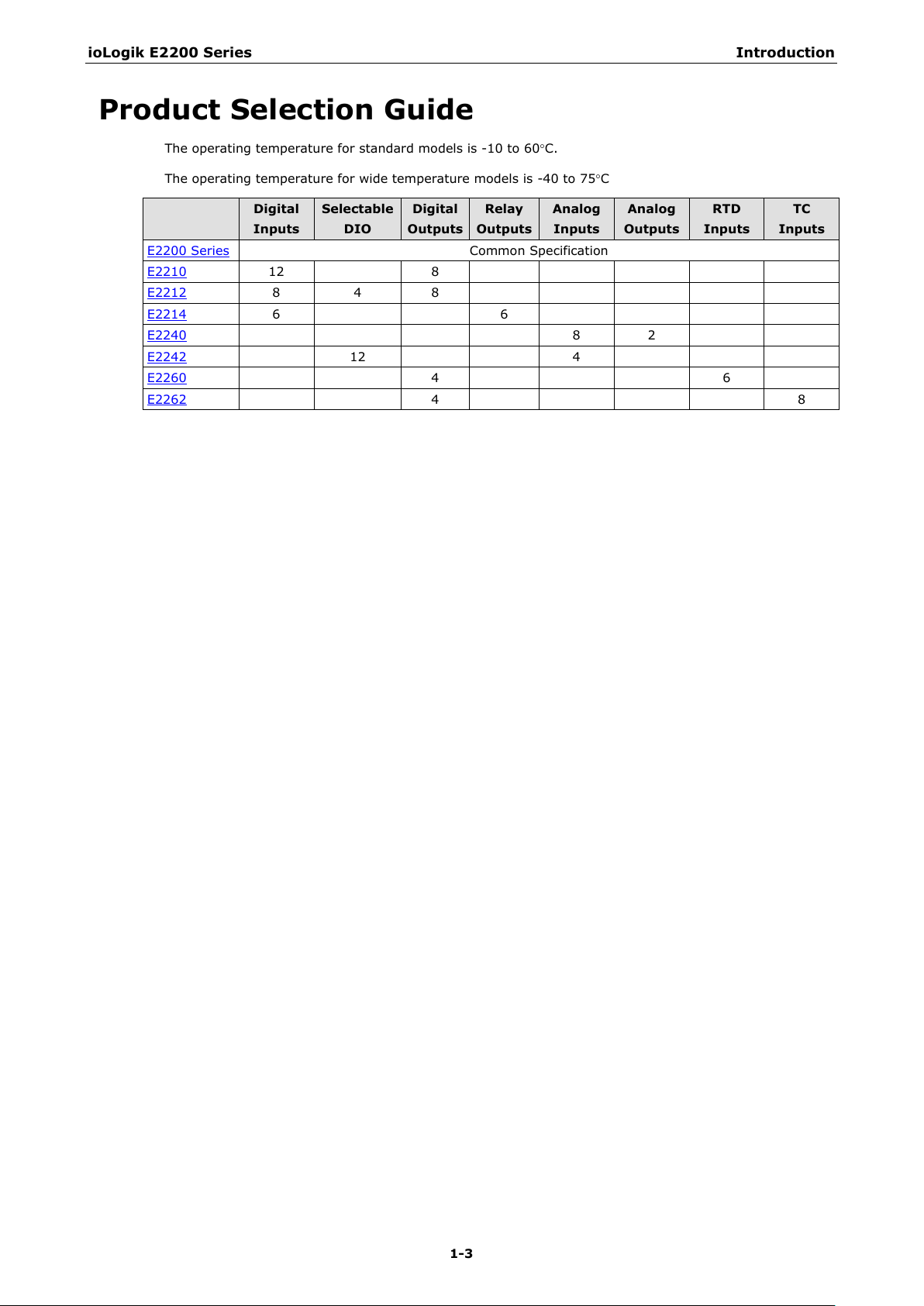
Product Selection Guide
The operating temperature for standard models is -10 to 60°C.
The operating temperature for wide temperature models is -40 to 75°C
Digital
Inputs
E2200 Series Common Specification
E2210 12 8
E2212 8 4 8
E2214 6 6
E2240 8 2
E2242 12 4
E2260 4 6
E2262 4 8
Selectable
DIO
Digital
Outputs
Relay
Outputs
Analog
Inputs
Analog
Outputs
RTD
Inputs
TC
Inputs
Page 9
ioLogik E2200 Series Introduction
1-4
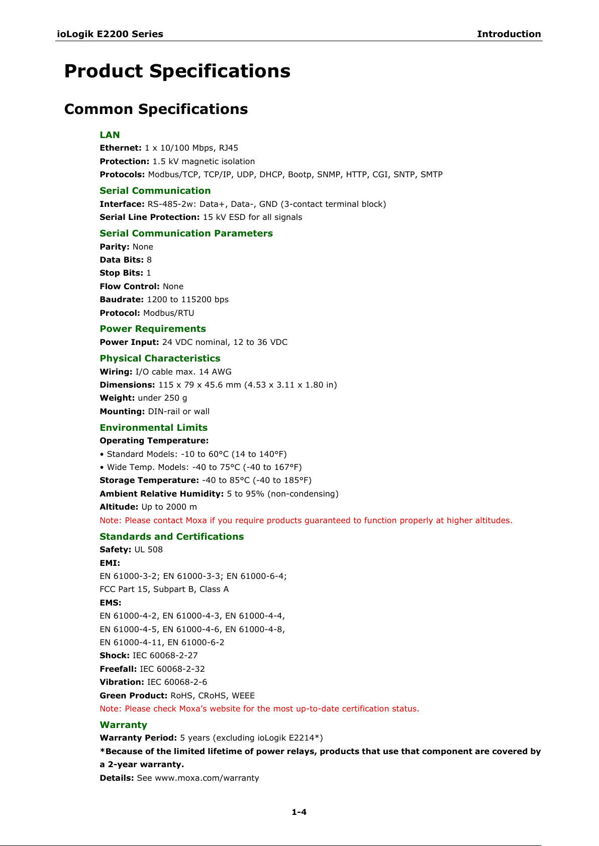
LAN
Ethernet:
Protection:
Protocols:
Serial Communication
Interface:
Serial Line Protection:
Serial Communication Parameters
Parity:
Data Bits:
Stop Bits:
Flow Control:
Baudrate:
Protocol:
Power Requirements
Power Input:
Physical Characteristics
Wiring:
Dimensions:
Weight:
Mounting:
Environmental Limits
Operating Temperature:
• Standard Models:
• Wide Temp. Models:
Storage Temperature:
Ambient Relative Humidity:
Altitude:
Note: Please
Standards and Certifications
Safety:
EMI:
EN 61000
FCC Part 15, Subpart B, Class A
EMS:
EN 61000
EN 61000
EN 61000
Shock:
Freefall:
Vibration:
Green Product:
Note: Please check Moxa’s website for the most up
Warranty
Warranty Period:
*Because of the limited lifetime of power relays, products that use that component are covered by
a 2
Details:
Product Specifications
Common Specifications
1 x 10/100 Mbps, RJ45
1.5 kV magnetic isolation
Modbus/TCP, TCP/IP, UDP, DHCP, Bootp, SNMP, HTTP, CGI, SNTP, SMTP
RS-485-2w: Data+, Data-, GND (3-contact terminal block)
15 kV ESD for all signals
None
8
1
None
1200 to 115200 bps
Modbus/RTU
24 VDC nominal, 12 to 36 VDC
I/O cable max. 14 AWG
115 x 79 x 45.6 mm (4.53 x 3.11 x 1.80 in)
under 250 g
DIN-rail or wall
-10 to 60°C (14 to 140°F)
-40 to 75°C (-40 to 167°F)
-40 to 85°C (-40 to 185°F)
5 to 95% (non-condensing)
Up to 2000 m
contact Moxa if you require products guaranteed to function properly at higher altitudes.
UL 508
-3-2; EN 61000-3-3; EN 61000-6-4;
-4-2, EN 61000-4-3, EN 61000-4-4,
-4-5, EN 61000-4-6, EN 61000-4-8,
-4-11, EN 61000-6-2
IEC 60068-2-27
IEC 60068-2-32
IEC 60068-2-6
RoHS, CRoHS, WEEE
-to-date certification status.
5 years (excluding ioLogik E2214*)
-year warranty.
See www.moxa.com/warranty
Page 10
ioLogik E2200 Series Introduction
1-5
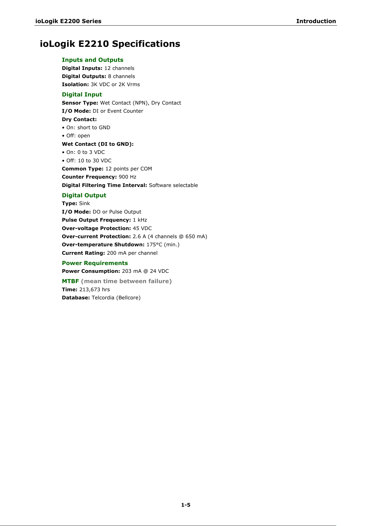
Inputs and Outputs
Digital Inputs:
Digital Outputs:
Isolation:
Digital Input
Sensor Type:
I/O Mode:
Dry Contact:
• On: short to GND
• Off:
Wet Contact (DI to GND):
• On: 0 to 3 VDC
• Off: 10 to 30 VDC
Common Type:
Counter Frequency:
Digital Filtering Time Interval:
Digital Output
Type:
I/O Mode:
Pulse Output
Over
Over
Over
Current Rating:
Power Requirements
Power Consumption:
MTBF (mean time between failure)
Time:
Database:
ioLogik E2210 Specifications
12 channels
8 channels
3K VDC or 2K Vrms
Wet Contact (NPN), Dry Contact
DI or Event Counter
open
12 points per COM
900 Hz
Software selectable
Sink
DO or Pulse Output
Frequency: 1 kHz
-voltage Protection: 45 VDC
-current Protection: 2.6 A (4 channels @ 650 mA)
-temperature Shutdown: 175°C (min.)
200 mA per channel
203 mA @ 24 VDC
213,673 hrs
Telcordia (Bellcore)
Page 11

ioLogik E2200 Series Introduction
1-6
Inputs and Outputs
Digital Inputs:
Digital Outputs:
Configurable DIOs:
Isolation:
Digital Input
Sensor Type:
I/O Mode:
Dry Contact:
• On: short to GND
• Off: open
Wet Contact (
• On: 0 to 3 VDC
• OFF: 10 to 30 VDC
Common Type:
Counter Frequency:
Digital Filtering Time Interval:
Digital Output
Type:
I/O Mode:
Pulse Output Frequency:
Over
Over
Over
Current Rating:
Power Requirements
Power Consumption:
MTBF
Time:
Database:
ioLogik E2212 Specifications
8 channels
8 channels
4 channels
3K VDC or 2K Vrms
Wet Contact (NPN or PNP) and Dry Contact
DI or Event Counter
DI to GND):
6 points per COM
900 Hz, power off storage
Software selectable
Sink
DO or Pulse Output
-voltage Protection: 45 VDC
-current Protection: 2.6 A (4 channels @650 mA)
-temperature Shutdown: 175°C (min.)
200 mA per channel
136 mA @ 24 VDC
(mean time between failure)
217,722 hrs
Telcordia (Bellcore)
1 kHz
Page 12

ioLogik E2200 Series Introduction
1-7
Inputs and Outputs
Digital Inputs:
Relay Outputs:
Isolation:
Digital Input
Sensor Type:
I/O Mode:
Dry Contact:
• On:
• Off: open
Wet Contact
• On: 0 to 3 VDC
• Off: 10 to 30 VDC
Common Type:
Counter Frequency:
Digital Filtering Time Interval:
Relay Output
Type:
Contact Current Rating:
• Inductive Load: 2 A @ 30 VDC, 250 VAC, 110 VAC
• Resistive Load: 5 A @ 30 VDC, 250 VAC, 110 VAC
Minimum permitted load:
Initial Insulation Resistance:
Mechani
Electrical endurance: 100,000 operations @ 5 A resistive load
Contact Resistance:
Pulse Output:
Power Requirements
Power Consumption:
MTBF (mean time between failure)
Time:
Database:
ioLogik E2214 Specifications
6 channels
6 channels
3K VDC or 2K Vrms
Wet Contact (NPN or PNP) and Dry Contact
DI or Event Counter
short to GND
(DI to GND):
3 points per COM
900 Hz, power off storage
Software selectable
Form A (N.O.) power relay
cal endurance: 1,000,000 operations
100 m ohms (max.)
0.3 Hz at rated load
170 mA @ 24 VDC
307,239 hrs
Telcordia (Bellcore)
1 A @ 5 VDC
1000 M ohms (min.) @ 500 VDC
Page 13
ioLogik E2200 Series Introduction
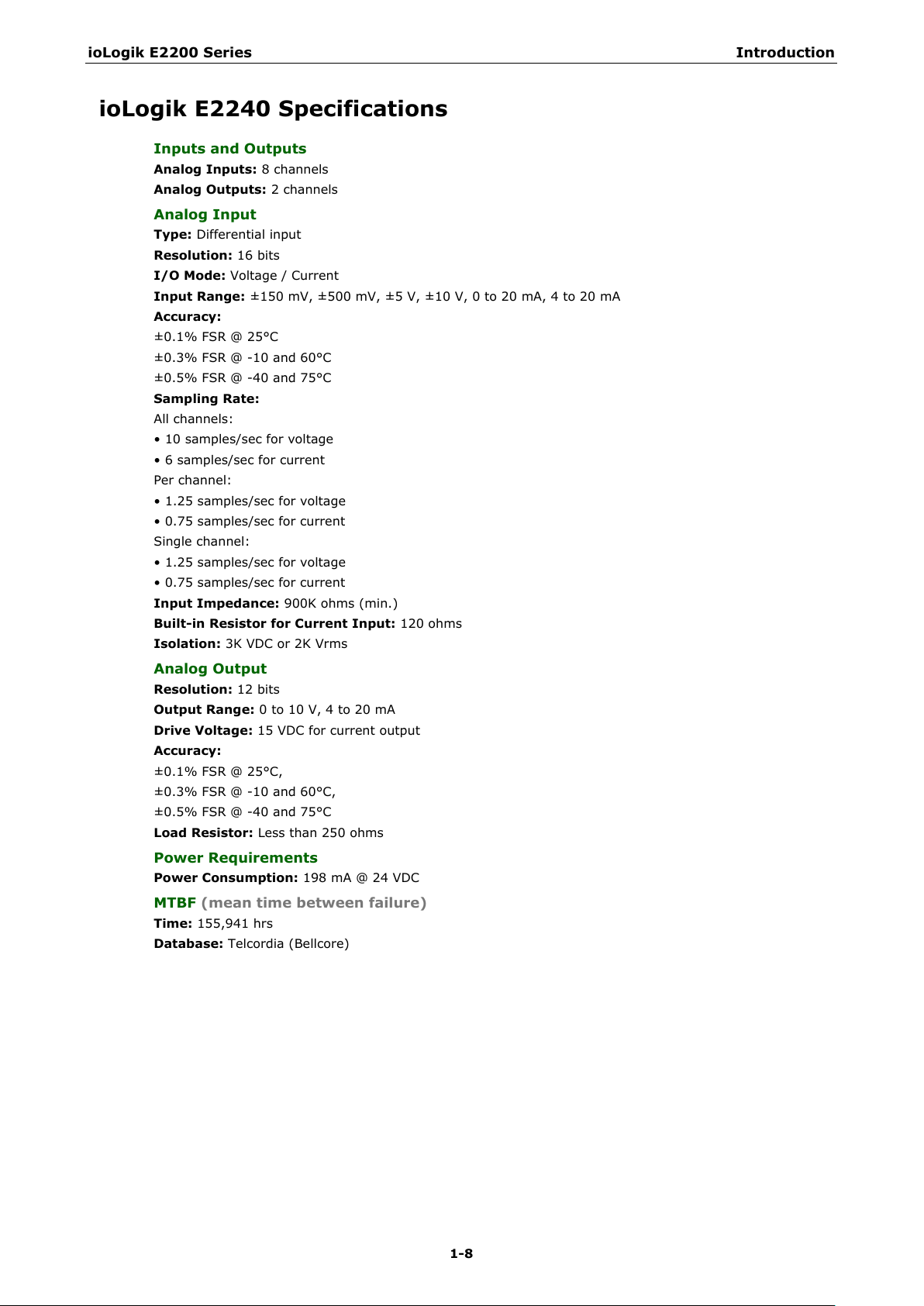
1-8
Inputs and Outputs
Analog Inputs:
Analog Outputs:
Analog Input
Type:
Resolution:
I/O Mode:
Input Range:
Accuracy:
±0.1% FSR @ 25°C
±0.3% FSR @
±0.5% FSR @
Sampling Rate:
All channels:
• 10 samples/sec for voltage
• 6 samples/sec for current
Per
• 1.25 samples/sec for voltage
• 0.75 samples/sec for current
Single channel:
• 1.25 samples/sec for voltage
• 0.75 samples/sec for current
Input Impedance:
Built
Isolation:
Analog Output
Resolution:
Output Range:
Drive Voltage:
Accuracy:
±0.1% FSR @ 25°C,
±0.3% FSR @
±0.5% FSR @
Load Resistor:
Power Requirements
Power Consumption:
MTBF (mean time between failure)
Time:
Database:
ioLogik E2240 Specifications
8 channels
2 channels
Differential input
16 bits
Voltage / Current
±150 mV, ±500 mV, ±5 V, ±10 V, 0 to 20 mA, 4 to 20 mA
-10 and 60°C
-40 and 75°C
channel:
900K ohms (min.)
-in Resistor for Current Input: 120 ohms
3K VDC or 2K Vrms
12 bits
0 to 10 V, 4 to 20 mA
15 VDC for current output
-10 and 60°C,
-40 and 75°C
Less than 250 ohms
155,941 hrs
Telcordia (Bellcore)
198 mA @ 24 VDC
Page 14

ioLogik E2200 Series Introduction
1-9
Inputs and Outputs
Analog Inputs:
Configurable DIOs:
Analog Input
Type:
Resolution:
I/O Mode:
Input Range: ±150 mV, 0 to 150 mV, ±500 mV, 0 to 500 mV, ±5 V, 0 to 5 V, ±10 V, 0 to 10 V, 0 to 20 mA,
4 to 20 mA
Accuracy:
±0.1% FSR @ 25°C
±0.3% FSR @
±0.5% FSR @
Sampling Rate:
All channels:
• 32 samples/sec
Per channel:
• 8 samples/sec
Single channel:
• 100 samples/sec
Input Impedance:
Built
Digital Input
Sensor Type:
I/O Mode:
Dry Contact:
• On: short to GND
• Off: Open
Wet Contact
• On: 0 to 3 VDC
• Off: 10 to 30 VDC
Common Type:
Isolation:
Counter
Digital Filtering Time Interval:
Digital Output
Type:
I/O Mode:
Pulse Output Frequency:
Over
Over
Over
Current Rating:
Isolation:
Power Requirements
Power Consumption:
MTBF (mean time between failure)
Time:
Database:
ioLogik E2242 Specifications
4 channels
12 channels
Differential input
16 bits
Voltage / Current
-10 and 60°C
-40 and 75°C
200K ohms (min.)
-in Resistor for Current Input: 120 ohms
Wet Contact (NPN or PNP) and Dry Contact
DI or event counter
(DI to GND):
6 points per COM
3K VDC or 2K Vrms
Frequency: 900 Hz, power off storage
Software selectable
Sink
DO or Pulse Output
1 kHz
-voltage Protection: 45 VDC
-current Protection: 2.6 A (4 channels @ 650 mA)
-temperature Shutdown: 175°C (min.)
200 mA per channel
3K VDC or 2K Vrms
178 mA @ 24 VDC
204,391 hrs
Telcordia (Bellcore)
Page 15
ioLogik E2200 Series Introduction
1-10
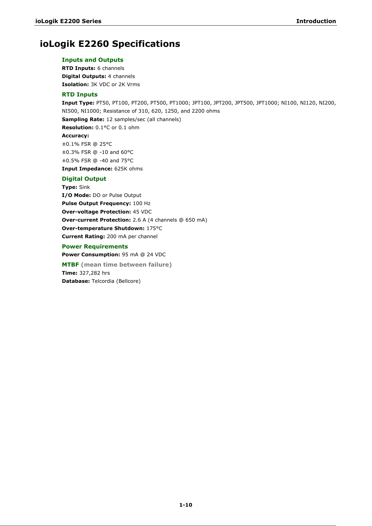
Inputs and Outputs
RTD Inputs:
Digital Outputs:
Isolation:
RTD Inputs
Input Type: PT50, PT100, PT200, PT500, PT1000; JPT100, JPT200, JPT500, JPT1000; NI100, NI120, NI200,
NI500, NI1000; Resistance of 310, 620, 1250, and 2200 ohms
Sampling Rate:
Resolution:
Accuracy:
±0.1% FSR @ 25°C
±0.
±0.5% FSR @
Input Impedance:
Digital Output
Type:
I/O Mode:
Pulse Output Frequency:
Over
Over
Over
Current Rating:
Power Requirements
Power Consumption:
MTBF (mean time between failure)
Time:
Database:
ioLogik E2260 Specifications
6 channels
4 channels
3K VDC or 2K Vrms
12 samples/sec (all channels)
0.1°C or 0.1 ohm
3% FSR @ -10 and 60°C
-40 and 75°C
625K ohms
Sink
DO or Pulse Output
100 Hz
-voltage Protection: 45 VDC
-current Protection: 2.6 A (4 channels @ 650 mA)
-temperature Shutdown: 175°C
200 mA per channel
95 mA @ 24 VDC
327,282 hrs
Telcordia (Bellcore)
Page 16
ioLogik E2200 Series Introduction
1-11
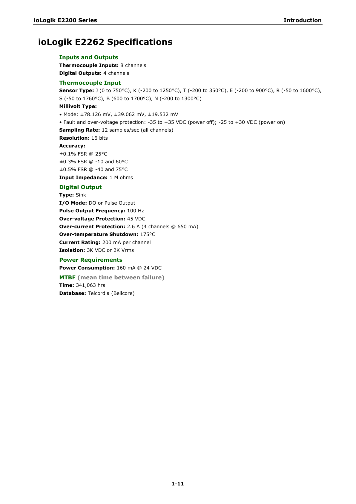
Inputs and Outputs
Thermocouple Inputs:
Digital Outputs:
Thermocouple Input
Sensor Type:
50 to 1600°C),
S (
Millivolt Type:
• Mode: ±78.126 mV, ±39.062 mV, ±19.532 mV
• Fault and over
Sampling Rate:
Resolution:
Accuracy:
±0.1% FSR @ 25°C
±0.3% FS
±0.5% FSR @
Input Impedance:
Digital Output
Type:
I/O Mode:
Pulse Output Frequency:
Over
Over
Over
Current Rating:
Isolation:
Power Requirements
Power Consumption:
MTBF
Time:
Database:
ioLogik E2262 Specifications
8 channels
4 channels
J (0 to 750°C), K (-200 to 1250°C), T (-200 to 350°C), E (-200 to 900°C), R (-
-50 to 1760°C), B (600 to 1700°C), N (-200 to 1300°C)
-voltage protection: -35 to +35 VDC (power off); -25 to +30 VDC (power on)
12 samples/sec (all channels)
16 bits
R @ -10 and 60°C
-40 and 75°C
1 M ohms
Sink
DO or Pulse Output
100 Hz
-voltage Protection: 45 VDC
-current Protection: 2.6 A (4 channels @ 650 mA)
-temperature Shutdown: 175°C
200 mA per channel
3K VDC or 2K Vrms
160 mA @ 24 VDC
(mean time between failure)
341,063 hrs
Telcordia (Bellcore)
Page 17
ioLogik E2200 Series Introduction
1-12
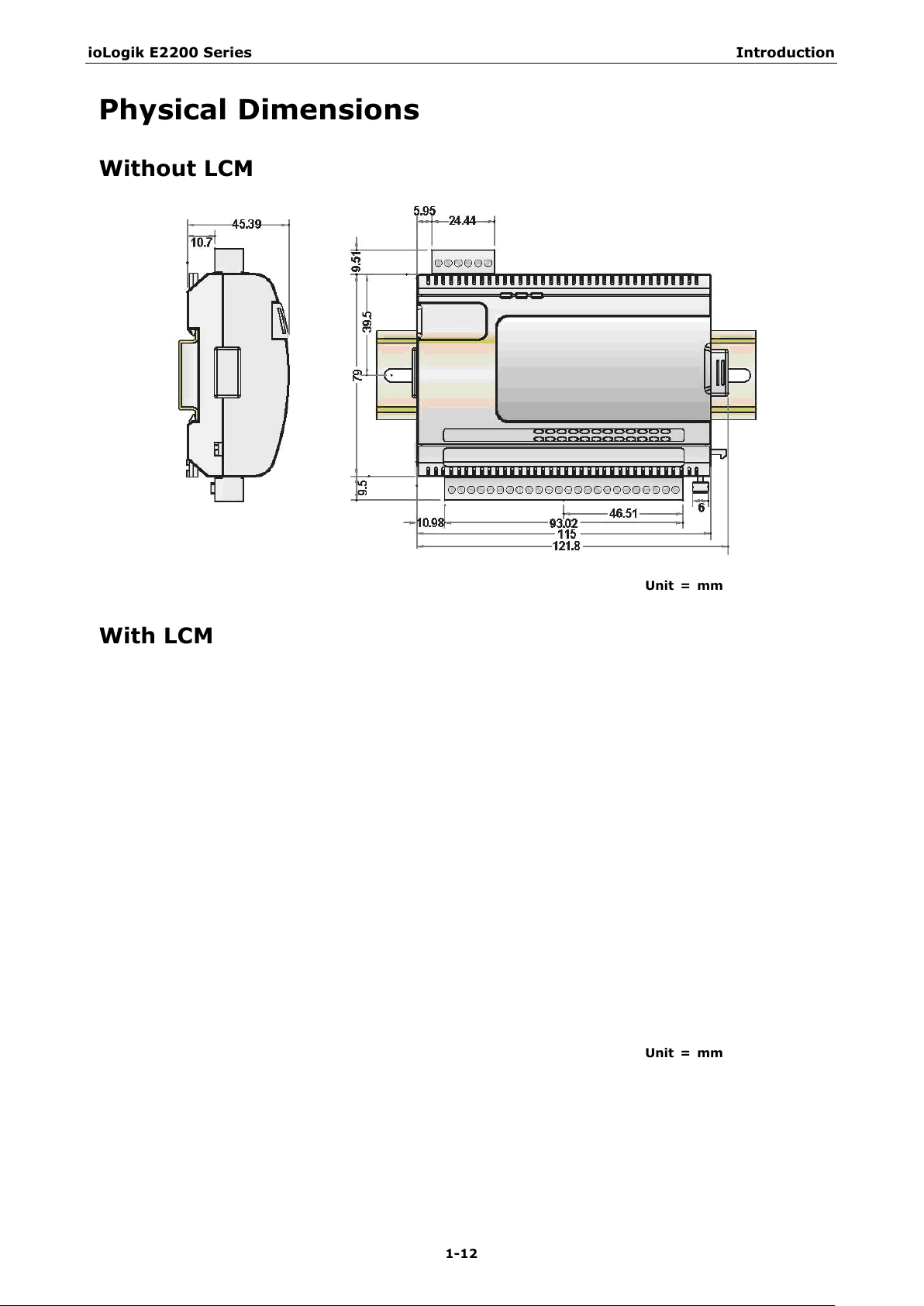
Physical Dimensions
Without LCM
With LCM
Unit = mm
Unit = mm
Page 18

ioLogik E2200 Series Introduction
1-13
NOTE
The RESET button restarts the device and resets all settings to factory defaults. Use a pointed object such as
a straightened paper clip to hold the RESET button down for 5 sec. The RDY LED will turn red as you are holding
the RESET button down. The factory defaults will be loaded once the RDY LED turns green again. At this point
you can release the RESET b
Hardware Reference
Panel Guide
TB1
TB2
Pin Assignments
System Bus
utton.
Pin 1 2 3 4 5
Signal V+ V- V+ V- NC
Pin 6 7 8 9 10
Signal NC Data+ SYNC Data- GND
Ethernet Port
Pin 1 2 3 4
Signal TXD+ TXD- RXD+ ---
Pin 5 6 7 8
Signal --- RXD- --- ---
Page 19
ioLogik E2200 Series Introduction
1-14
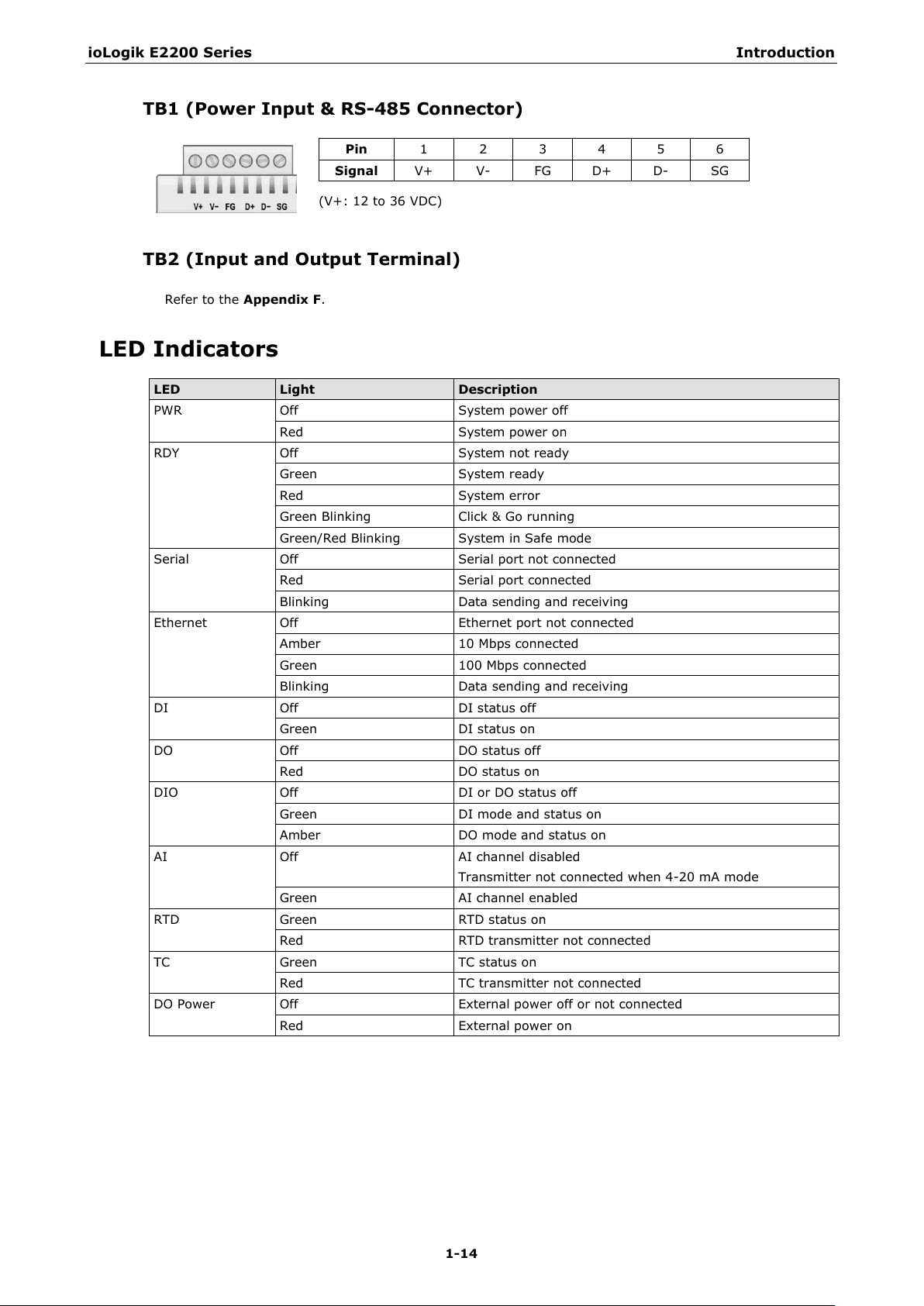
(V+: 12 to
TB1 (Power Input & RS-485 Connector)
Pin 1 2 3 4 5 6
Signal V+ V- FG D+ D- SG
TB2 (Input and Output Terminal)
Refer to the Appendix F.
LED Indicators
LED Light Description
PWR Off System power off
Red System power on
RDY Off System not ready
Green System ready
Red System error
Green Blinking Click & Go running
Green/Red Blinking System in Safe mode
Serial Off Serial port not connected
Red Serial port connected
Blinking Data sending and receiving
Ethernet Off Ethernet port not connected
Amber 10 Mbps connected
Green 100 Mbps connected
Blinking Data sending and receiving
DI Off DI status off
Green DI status on
DO Off DO status off
Red DO status on
DIO Off DI or DO status off
Green DI mode and status on
Amber DO mode and status on
AI Off AI channel disabled
Green AI channel enabled
RTD Green RTD status on
Red RTD transmitter not connected
TC Green TC status on
Red TC transmitter not connected
DO Power Off External power off or not connected
Red External power on
36 VDC)
Transmitter not connected when 4-20 mA mode
Page 20

2
2. Initial Setup
This chapter describes how to install the ioLogik E2200 series.
The following topics are covered in this chapter:
Hardware Installation
Connecting the Power
Grounding the Unit
Software Installation
Restore Factory Defaults
Connecting to ioAdmin via Ethernet
Configuring the Host Computer’s IP Address
Activating ioAdmin and Connecting to the ioLogik
Adding More I/O Channels
Setting the RS-485 Baudrate
I/O Wiring Diagrams
Using ioAdmin to Import/Export Configurations
Page 21

ioLogik E2200 Series Initial Setup
2-2
ATTENTION
Determine the maximum possible current for each power wire and common wire. Observ
maximum current allowable for each wire size. If the current exceeds the maximum rating, the wiring could overheat, causing
serious damage to your equipment. For safety reasons, we recommend an average cable size of 22
depending on the current load, you may want to adjust your cable size (the maximum wire size for power connectors is 2
mm)..
Hardware Installation
Connecting the Power
Connect the 12 to 36 VDC power line to the ioLogik’s terminal block (TB1). If power is properly supplied, the
power LED will glow a solid red color.
Grounding the Unit
The ioLogik is equipped with two grounding points, one on the wall mount socket and the other on the
DIN-Rail mount. Both grounding points are connected to the same conducting pathway Connect the ground
pin if earth ground is available.
Software Installation
ioAdmin is a Windows utility provided for the configuration and management of ioLogik E2200 products and
connected I/O devices. ioAdmin can be used to monitor and configure ioLogik E2200 products from anywhere
on the network. Some settings may also be configured by web console or optional LCM.
ioAdmin can be downloaded from Moxa’s website.
1. Installing ioAdmin from website:
a. First click on the following link to access the website’s search utility:
http://www.moxa.com/support/search.aspx?type=soft
b. When the web page opens, enter the model name of your product in the search box.
c. Click the model name and navigate to the product page, and then click on Utilities, located in the box
titled Software.
d. Download and then unzip the file. Run SETUP.EXE from that location.
The installation program will guide you through the installation process and install the software.
2. Open ioAdmin: After installation is finished, run ioAdmin from the Windows Start menu: Start
Program Files
3. Search the network for ioLogik: When ioAdmin is started, it will automatically run the auto search
program. You can also find the program on the menu bar; select System
devices. A dialog window will appear. Click Start Search to begin searching for your unit.
MOXA IO Server Utility ioAdmin.
e all electrical codes dictating the
AWG. However,
Auto Scan Active ioLogik
Page 22
ioLogik E2200 Series Initial Setup
2-3
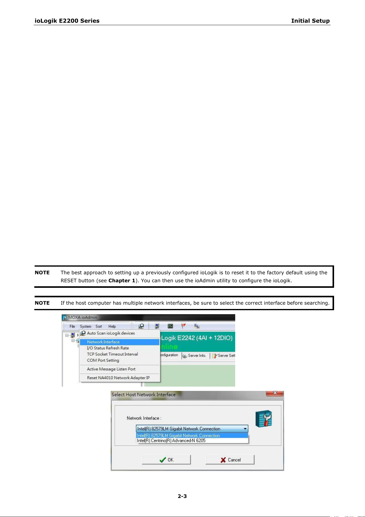
NOTE
The best approach to setting up
RESET button
NOTE
If the host computer has multiple network interfaces, be sure to select the correct interface before searching.
(see Chapter 1). You can then use the ioAdmin utility to configure the ioLogik.
a previously configured ioLogik is to reset it to the factory default using the
Page 23
ioLogik E2200 Series Initial Setup
2-4
Restore Factory Defaults
There are three ways to restore the ioLogik to factory default settings.
1. Hold the RESET button for 5 seconds.
2. Right-click on the specifc ioLogik in the ioAdmin utility and select Reset to Default.
3. Select Load Factory Default from the web console.
Connecting to ioAdmin via Ethernet
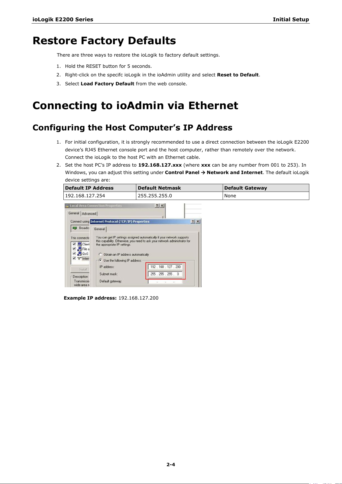
Configuring the Host Computer’s IP Address
1. For initial configuration, it is strongly recommended to use a direct connection between the ioLogik E2200
device’s RJ45 Ethernet console port and the host computer, rather than remotely over the network.
Connect the ioLogik to the host PC with an Ethernet cable.
2. Set the host PC’s IP address to 192.168.127.xxx (where xxx can be any number from 001 to 253). In
Windows, you can adjust this setting under Control Panel
device settings are:
Default IP Address Default Netmask Default Gateway
192.168.127.254 255.255.255.0 None
Network and Internet. The default ioLogik
Example IP address: 192.168.127.200
Page 24
ioLogik E2200 Series Initial Setup
2-5
NOTE
When setting up a previously configured ioLogik, first restore it to factory default settings by using the RESET
button
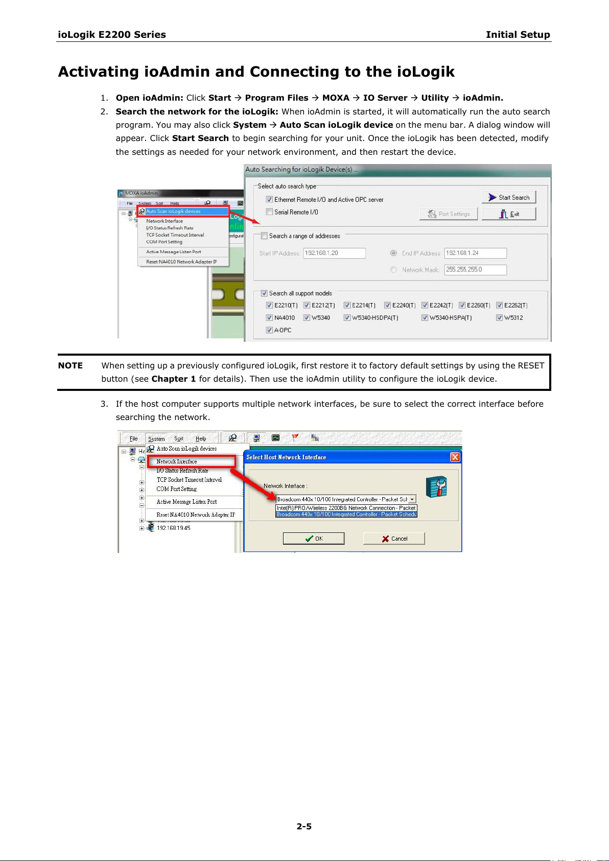
Activating ioAdmin and Connecting to the ioLogik
1. Open ioAdmin: Click Start Program Files MOXA IO Server Utility ioAdmin.
2. Search the network for the ioLogik: When ioAdmin is started, it will automatically run the auto search
program. You may also click System Auto Scan ioLogik device on the menu bar. A dialog window will
appear. Click Start Search to begin searching for your unit. Once the ioLogik has been detected, modify
the settings as needed for your network environment, and then restart the device.
(see Chapter 1 for details). Then use the ioAdmin utility to configure the ioLogik device.
3. If the host computer supports multiple network interfaces, be sure to select the correct interface before
searching the network.
Page 25
ioLogik E2200 Series Initial Setup
2-6
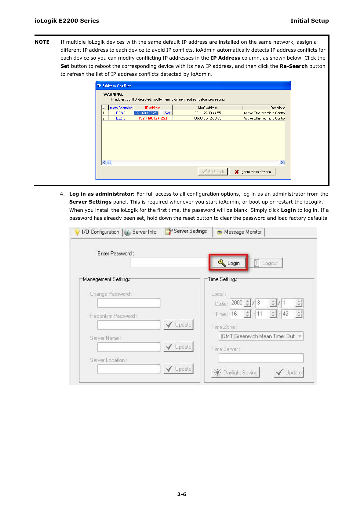
NOTE
If multiple ioLogik devices
different IP address to each device to avoid IP conflicts. ioAdmin automatically detects IP address conflicts for
each
column, as shown below. Click the
Set
button
to refresh the list of
device so you can modify conflicting IP addresses in the IP Address
button to reboot the corresponding device with its new IP address, and then click the Re-Search
4. Log in as administrator: For full access to all configuration options, log in as an administrator from the
Server Settings panel. This is required whenever you start ioAdmin, or boot up or restart the ioLogik.
When you install the ioLogik for the first time, the password will be blank. Simply click Login to log in. If a
password has already been set, hold down the reset button to clear the password and load factory defaults.
with the same default IP address are installed on the same network, assign a
IP address conflicts detected by ioAdmin.
Page 26
ioLogik E2200 Series Initial Setup
2-7
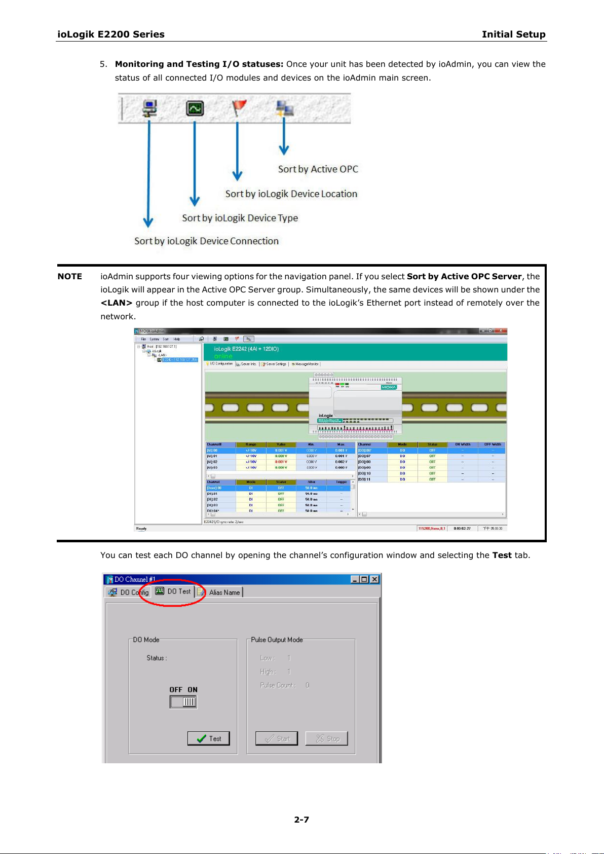
NOTE
ioAdmin supports four viewing options for the navigation panel. If you select
, the
ioLogik will appear in the Active OPC Server group. Simultaneously, the same devices will be shown under the
<LAN>
ly over the
network.
5. Monitoring and Testing I/O statuses: Once your unit has been detected by ioAdmin, you can view the
status of all connected I/O modules and devices on the ioAdmin main screen.
group if the host computer is connected to the ioLogik’s Ethernet port instead of remote
You can test each DO channel by opening the channel’s configuration window and selecting the Test tab.
Sort by Active OPC Server
Page 27
ioLogik E2200 Series Initial Setup
2-8
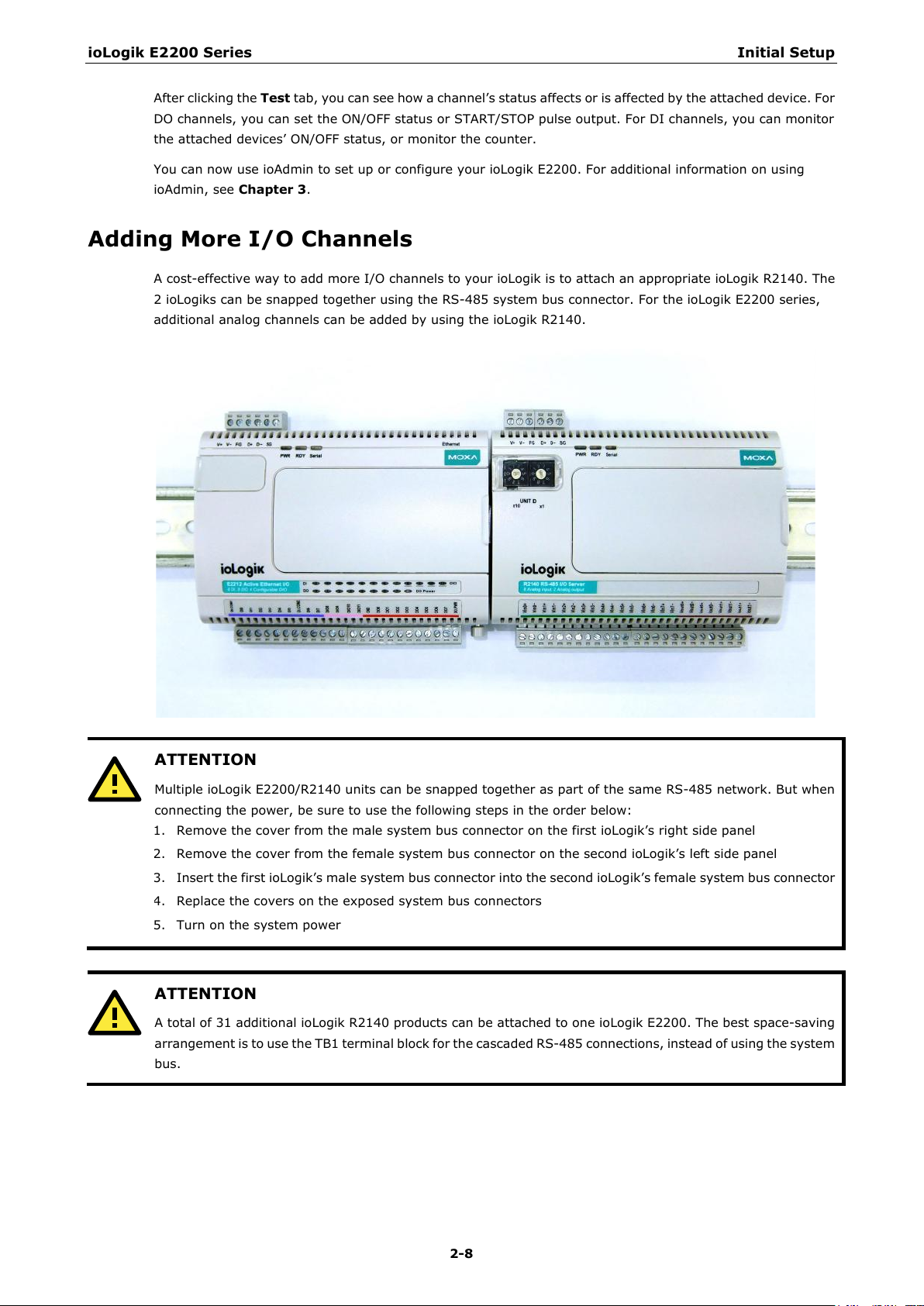
ATTENTION
Multiple ioLogik E2200/R21
485 network. But when
connecting the power, be sure to use the following steps in the order below:
ATTENTION
A total of 31 additional ioLogik R21
saving
arrangement is to use the TB1 terminal block for the cascaded RS-485 connections, instead of using the system
bus.
After clicking the Test tab, you can see how a channel’s status affects or is affected by the attached device. For
DO channels, you can set the ON/OFF status or START/STOP pulse output. For DI channels, you can monitor
the attached devices’ ON/OFF status, or monitor the counter.
You can now use ioAdmin to set up or configure your ioLogik E2200. For additional information on using
ioAdmin, see Chapter 3.
Adding More I/O Channels
A cost-effective way to add more I/O channels to your ioLogik is to attach an appropriate ioLogik R2140. The
2 ioLogiks can be snapped together using the RS-485 system bus connector. For the ioLogik E2200 series,
additional analog channels can be added by using the ioLogik R2140.
Remove the cover from the male system bus connector on the first ioLogik’s right side panel
Remove the cover from the female system bus connector on the second ioLogik’s left side panel
Insert the first ioLogik’s male system bus connector into the second ioLogik’s female system bus connector
Replace the covers on the exposed system bus connectors
Turn on the system power
40 units can be snapped together as part of the same RS-
40 products can be attached to one ioLogik E2200. The best space-
Page 28
ioLogik E2200 Series Initial Setup
2-9
ATTENTION
All I/O channels of the ioLogik E2200
ost PC, but Click&Go logic can
only be used with the ioLogik E2200 series. Currently, Click&Go local control logic is not supported by the
ioLogik R21
ATTENTION
When using the RS
485
Modbus devices, the ioLogik E2200 should always have an RS
ioLogik R21
E2200 series supports Unit IDs up to 247 for Modbus devices, the highest Unit ID on the ioLogik R2140 is 99.
40 series.
-485 cascading interface or system bus to add more I/O channels or to connect to RS-
40 or other devices should always be 2 or more, with an upper limit of 99. Although the ioLogik
+R2140 system can be polled by a remote h
Setting the RS-485 Baudrate
The RS-485 port on the ioLogik E2200 series is reserved for connecting to another RS-485 I/O device. The
RS-485 port can run Modbus/RTU or I/O command sets. The baudrate is set by a physical dial on the top of the
ioLogik. The default settings are: baudrate = 115200; parity check = N; data bits = 8; and stop bit = 1.
Baudrate for RS-485
(parameters are N, 8, 1)
Remember to restart the ioLogik after making any changes to the RS-485 baudrate.
Dial setting and corresponding baudrate:
0:115200 1:57600 2:38400 3:19200
4:9600 5:4800 6:2400 7:1200
-485 Unit ID of 1. The Unit ID of the attached
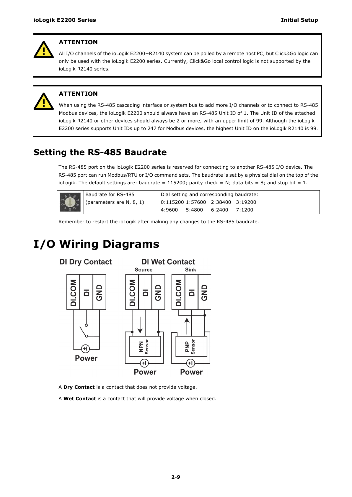
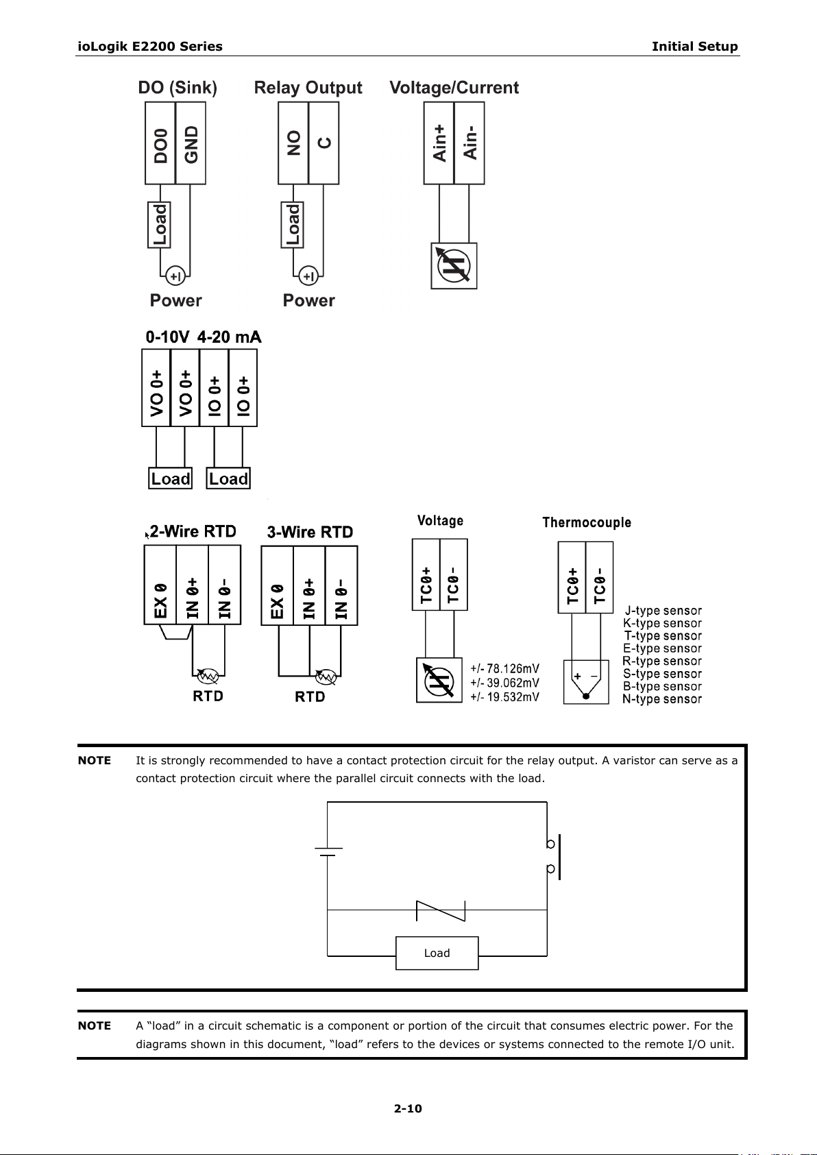
I/O Wiring Diagrams
A Dry Contact is a contact that does not provide voltage.
A Wet Contact is a contact that will provide voltage when closed.
Page 29
ioLogik E2200 Series Initial Setup
2-10
NOTE
It is strongly recommended to have a contact protection circuit for the relay output. A varistor can serve as a
contact pro
NOTE
A “load” in a circuit schematic is a component or portion of the circuit that consumes electric power. For the
diagrams shown in this document, “load” refers to the devices
tection circuit where the parallel circuit connects with the load.
Load
or systems connected to the remote I/O unit.
Page 30
ioLogik E2200 Series Initial Setup
2-11
ATTENTION—Dry Contacts
When connecting an I/O device to the ioLogik’s dry contacts, connect DI.COM
to the power of the external sensor to avoid affecting other channels.
DI.COM input power should be between 12 to 36 VDC.
ATTENTION—DIO Channels
Sensor types are grouped, with DI
group. If an NPN sensor is connected to DI-0, then only NPN sensors can be connected to the other DI channels
in the group (i.e., DI
, then only PNP sensors
can be connected to
O-4 and DIO-5). Likewise, if a PNP sensor is connected to DIO-6
the other DI channels in the group (i.e., DIO-10 and DIO-11).
O-0 to DIO-5 forming one group and DIO-6- to DIO-11 forming another
The
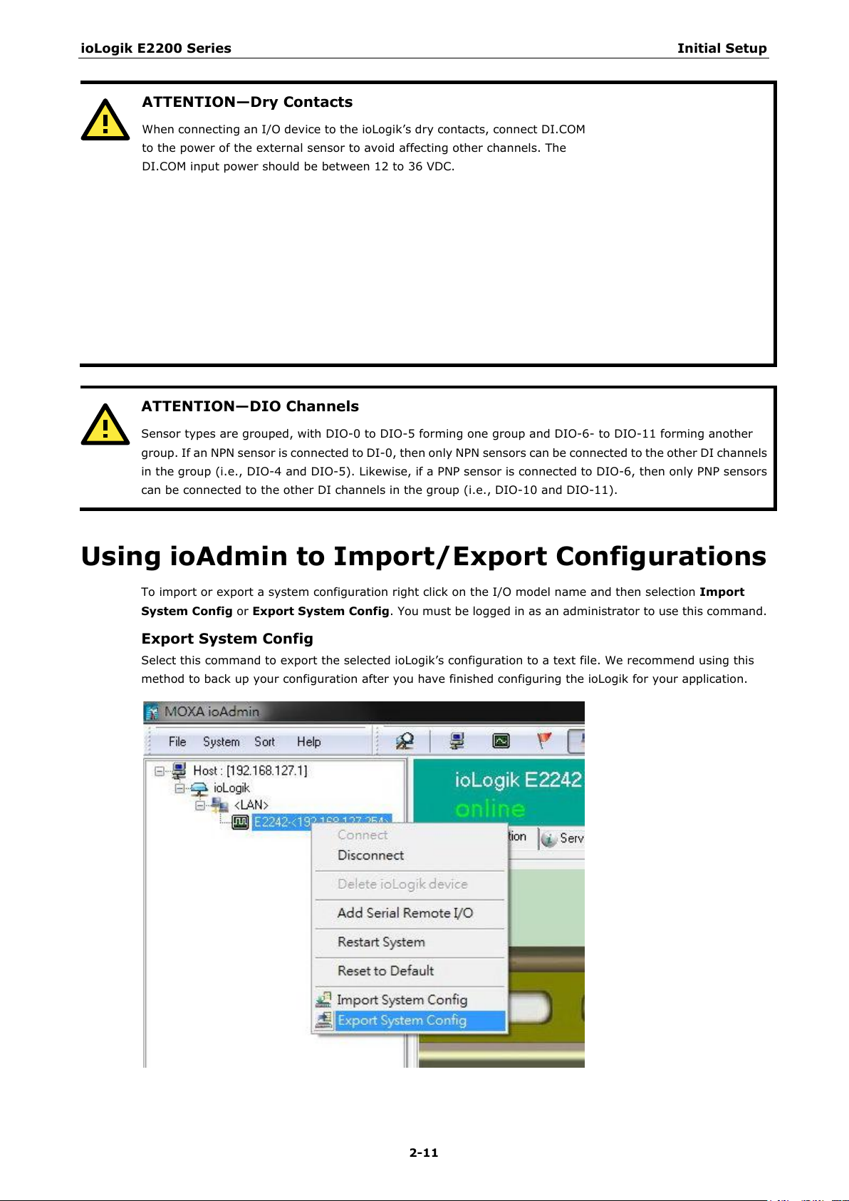
Using ioAdmin to Import/Export Configurations
To import or export a system configuration right click on the I/O model name and then selection Import
System Config or Export System Config. You must be logged in as an administrator to use this command.
Export System Config
Select this command to export the selected ioLogik’s configuration to a text file. We recommend using this
method to back up your configuration after you have finished configuring the ioLogik for your application.
Page 31

ioLogik E2200 Series Initial Setup
2-12
ATTENTION
Since there are major functional differences between firmware versions, exporting the configuration file
requires a longer processing time.
ioAdmin 3.10 or above, especially if earlier versions of ioAdmin have been installed and then
Adjust the TCP Socket Timeout Interval to 30 seconds when using
removed.
Import System Config
Select this command to load a configuration for the selected ioLogik from a configuration text file. The new
configuration will not take effect until the ioLogik has been restarted. This command can be used to restore a
configuration after loading the factory defaults, or to duplicate a configuration to multiple ioLogik units.
Page 32

3
3. Using ioAdmin
In this chapter, we explain how to use ioAdmin to configure your ioLogik product.
The following topics are covered in this chapter:
System Requirements
Features of ioAdmin
ioAdmin Overview
Main Screen Overview
Title
Menu Bar
Quick Links
Navigation Panel
Main Window
Sync Rate Status
Status Bar
ioAdmin Administrator Functions
I/O Configuration Tab (Administrator)
Server Settings Tab (Administrator)
Network Tab
Firmware Update Tab
Watchdog Tab
Click&Go Logic Tab
Active Tags Tab
SNMP Settings Tab
Message Monitor Panel (General)
Server Context Menu
Using ioEventLog
Installing ioEventLog
Basic Functions
Configuration
Checking Connected Devices
Opening Log Files
Clearing the Log
Page 33

ioLogik E2200 Series Using ioAdmin
3-2
System Requirements
The ioLogik E2200 series device can be managed and configured by Ethernet with the ioAdmin Windows utility.
ioAdmin’s graphical user interface provides easy access to all status information and settings. ioAdmin can also
be used to configure Click&Go rules to handle front-end events.
Hardware Requirements
CPU Intel Pentium (Pentium 4 and above)
RAM 512 MB (1024 MB recommended)
Network Interface 10/100Mb Ethernet
Software Requirements
Operating System Microsoft Windows 2000, XP or later
Editor(Not necessary) Microsoft Office 2003 (Access 2003) or later
Features of ioAdmin
Remote management
Use ioAdmin to perform the following task over an Ethernet network:
• Search and configure multiple ioLogiks
• Monitor and control I/O statuses
• Use active message monitoring
• Configure Click&Go local control logic
• Upgrade the firmware
• Restart the ioLogik
• Restore factory default settings
On-line Wiring Guide
For added convenience, a wiring guide is available inside the ioAdmin utility to save time when troubleshooting
or expanding a network.
Configuration File
ioAdmin helps you save all ioLogik configurations as a file. The file is viewable in text format and can be used
as a:
• Record or backup of your configuration
• Template for configuring other ioLogik units
• Quick reference guide for configuring Modbus drivers in a SCADA system
The file includes the following information:
• File name, date, and time
• Model information
• System configuration
• I/O Modbus address
Device Management List
ioAdmin can import and export a list of ioLogik devices that are being managed. This file can make it easier to
manage all devices on the network, and includes the following information:
• Device name
• Module
• IP address
• Unit ID
Page 34

ioLogik E2200 Series Using ioAdmin
3-3
Server Management List
ioAdmin can import and export a list of ioLogik units
that are being managed. This file can make it easier
to manage all devices on the network, and includes
the following information:
•
•
•
•
1
2
4
6
5
7
3
Server name
Module
IP address
Unit ID
ioAdmin Overview
Main Screen Overview
The main screen of the ioAdmin utility defaults to the I/O Configuration tab, which displays a figure of your
ioLogik device with the status of each of its I/O channels. The other tabs on the main screen take you to server
and network settings, and further functions are available when you log on to the ioLogik. Note that
configuration options are not available unless you log on as an administrator.
ioAdmin Main Screen
1. Title
2. Menu bar
3. Quick link
4. Navigation panel
5. Main window
6. Sync. rate status
7. Status bar
Page 35

ioLogik E2200 Series Using ioAdmin
3-4
Title
The Title shows you which program is opened. In this case, it indicates that Moxa ioAdmin is running.
Menu Bar
The Menu bar has four items:
1.
File
2. System
3. Sort
4. Help
File
From the File menu, you can export the list of ioLogiks currently displayed in the navigation panel. You can also
import a list into ioAdmin.
When importing/exporting a device list, you will be prompted to select which ioLogik on the list needs to be
imported or exported. When a popup window appears, click the “folder” icon to select/key-in the file name to
save/import a specific file.
The file will have an .SLT extension and can be opened as a text file. The server list will provide the basic
information for each server, such as Device Name, Model, IP address, and Unit ID.
Page 36

ioLogik E2200 Series Using ioAdmin
3-5
Several operations can be accessed from the
System
System menu.
Auto Scan ioLogik Devices
The Auto Scan ioLogik Devices function searches for ioLogiks on the network automatically. When
connecting for the first time, or when recovering from a network disconnection, you can use this command to
find any ioLogik that is connected to the physical network.
You can search for ioLogik devices by type, IP address range, or model name. Click Start Search to start
searching and the search results will be shown at the bottom of the window.
Select auto search type
Search for an ioLogik device by whether it is an Smart Ethernet Remote I/O Device or RS-232/485
remote I/O.
Search a range of addresses
Search for ioLogik devices within a range of IP address addresses by defining a starting IP address and an
ending IP address, or by using the netmask.
Search all support models
Select the specific model number(s) of the ioLogik devices you wish to search for.
Page 37

ioLogik E2200 Series Using ioAdmin
3-6
Network Interface
Network Interface allows you to select a network interface to use (if the PC has multiple network adaptors
installed). The default network interface will be the same as the Windows setting. Make sure the interface is
correct when connecting to the ioLogik device; otherwise, no devices will be found.
I/O Status Refresh Rate
This operation is used to adjust how often the ioLogik is polled for device status by the ioAdmin utility. The
current rate is displayed on the status bar at the bottom of the window.
Note: The higher sync rates result in higher loads on the network.
TCP Socket Timeout Interval
This operation allows you to select the preferred timeout value for TCP socket communication. When the
ioLogik's E2200 connection to the server exceeds a specified time period the device will automatically release
its modbus/TCP connection to the server, to free up the port for the next connection (default: 30 seconds).
Page 38

ioLogik E2200 Series Using ioAdmin
3-7
COM Port Setting
This operation is used to set the default parameters for the ioAdmin utility to establish a Modbus connection,
such as baudrate, data bits, and timeout interval. For most applications, this will involve connecting to ioLogik
R-series devices.
Active Message Listen Port
This operation specifies the port number to use for Active Messages. If your network uses a firewall, you can
coordinate this setting with your firewall settings to ensure that active messages get through.
Reset NA4010 Network Adaptor IP
This operation is used to re-assign an IP address to the NA-4010 network as reported by the ioLogik W5300
series adaptor, for ioLogik 4000 systems.
Page 39

ioLogik E2200 Series Using ioAdmin
3-8
Sort
The Sort menu allows the Devices list in the navigation panel to be sorted by connection, model, location, or
Active OPC.
Help
In the Help menu, you can view wiring guides and information about ioAdmin.
Page 40

ioLogik E2200 Series Using ioAdmin
3-9
Wiring Guides
ioAdmin provides a wiring guide for the ioLogik E2200 series. You can access the wiring guide by right-clicking
the ioLogik figure in the I/O Configuration tab. Select “Wiring Guide” in the submenu to open a help file showing
the unit’s wiring information and electrical characteristics (or refer to cable wiring).
You can also access the On-line Wiring Guide through the Help menu on the menu bar.
Page 41

ioLogik E2200 Series Using ioAdmin
3-10
This icon provides a direct link to start running the
These icons allow you to sort the ioLogik devices viewed in the Navigation
Panel according to the following criteria:
NOTE
The default location is
00, the navigation panel
will group all
Quick Links
Quick Links toolbard contains a collection of commonly used functions, including the Search and the Sort
functions.
Auto Scan ioLogik Devices
Auto Scan ioLogik Devices function.
Sorting Methods
Icon Function Name Navigation Panel View
Sort by ioLogik Device Connection
Sort by ioLogik Device Type
Sort by ioLogik Device Location
Sort by Active OPC Server
Empty locations together.
Empty. If you do not specify the location for the ioLogik E22
Navigation Panel
The Navigation Panel shows an overview of the ioLogik devices on the network as defined by the sorting
method. The default sorting view is By Connection. You can choose a different sorting method by clicking on
a different quick link button. The Navigation Panel also includes additional functions, such as Connect and
Disconnect. More advanced functions require the administrator’s password.
Access the function menu by right-clicking on the ioLogik model name in the navigation panel. The menu lists
both basic functions and advanced functions:
Page 42

ioLogik E2200 Series Using ioAdmin
3-11
Basic Functions: Add, Connect, and Disconnect
Add ioLogik ioLogik device: Select ioLogik tag and right click the tag. Select the “Add ioLogik device”
command to add an ioLogik device or Active OPC server manually.
Connect: Select the “Connect” command to try connecting over the network to the selected ioLogik.
Disconnect: Select the “Disconnect” command to drop the network connection with the selected ioLogik.
Advanced Functions: Delete, Restart, Reset, Import/Export Config File
You must be logged in as administrator to use these commands.
Delete ioLogik device: Select this command to remove the selected ioLogik.
Note: The target must be disconnected first to use this command.
Restart System: Select this command to restart the selected ioLogik.
Reset to Default: Select this command to reset all settings on the selected ioLogik, including console
password, to factory default values.
Export System Config: Select this command to export the selected ioLogik’s configuration to a text file. We
strongly recommend that you use this method to back up your configuration after you have finished configuring
the ioLogik for your application.
Import System Config: Select this command to load a configuration for the selected ioLogik from a
configuration text file. The new configuration will not take effect until the ioLogik has been restarted. This
command can be used to restore a configuration after loading the factory defaults, or to duplicate a
configuration to multiple ioLogik units.
Page 43

ioLogik E2200 Series Using ioAdmin
3-12
Main Window
I/O Configuration Tab (General)
The I/O Configuration tab shows the status of every I/O channel. This is the default tab when you first open
ioAdmin. Input channels are listed on the left and output channels are listed on the right.
Server Info Tab
Server information, such as firmware version, is displayed in the Server Info tab.
Page 44

ioLogik E2200 Series Using ioAdmin
3-13
Server Settings Tab (General)
The Server Settings tab is where you log in as an ioAdmin administrator. This is required in order to gain
access to the ioLogik configuration options. If a password has not been configured, simply click Login and leave
the Password entry field blank. Refer to the ioAdmin Administrator Functions section later on in this chapter
for details.
Message Monitor Tab
The Message Monitor tab will display any TCP/UDP Active Messages reported by the ioLogik E2200 series.
When you install the unit for the first time, the ruleset will not have been defined yet, so there will be no
messages in the Message Monitor Tab. When a ruleset has been defined and activated, any TCP/UDP messages
that have been triggered by sensor events will be shown in the Message Monitor tab. Please refer to Chapter 5
for information on how to define rules for active I/O messaging.
Page 45

ioLogik E2200 Series Using ioAdmin
3-14
NOTE
The
ATTENTION
You MUST log in to access administrator functions, including Network, Communication Watchdog Timer, and
Firmware Update tabs. If you forget the password, hold down the reset button to clear the password and load
fac
This will result in the loss of all configuration settings and your Click&Go logic rules
that have already been configured.
Messages can be displayed in ASCII or in HEX. To display messages in HEX, make sure that “Toggle HEX” is
checked.
Sync Rate Status
The current sync rate is displayed on the bar at the bottom of the window. The number shows how often the
ioLogik is polled for device status from the ioAdmin utility. The rate can be adjusted by clicking Menu Bar
System I/O Status Refresh Rate
higher sync rates result in higher loads on the network.
Status Bar
The status bar shows ioAdmin status information, such as program ready, searching ioLogik I/O, time, etc.
ioAdmin Administrator Functions
For full access to all configuration options, log in as an administrator in the Server Settings tab. This is required
whenever you start up ioAdmin or boot up/restart the ioLogik. When you install the ioLogik for the first time,
the password will be blank and you can simply click Login. Additional functions will available after logging in,
including the following new tabs:
When making configuration changes, you will need to click Update or Apply to save the changes. Some
changes will require that the unit be restarted in order to take effect.
I/O Configuration
1.
2. Server Setting (Admin)
3. Network
4. Firmware Update
5. Click&Go Logic
6. Watchdog
7. Active Tag
8. SNMP Setting
9. Message Monitor
tory defaults.
Page 46

ioLogik E2200 Series Using ioAdmin
3-15
NOTE
To show or hide the image of the ioLogik device, right
View
will hide the
image.
I/O Configuration Tab (Administrator)
When logged in as an administrator, double-click on a channel in the I/O Configuration tab to configure that
channel’s settings. A window will open with configuration options for that channel. After configuraing the
channel as desired, click Apply to implement the new settings.
Configuring Analog Input Channels
1.
2. Configuring Analog Output Channels
3. Configuring DIO Channels
4. Configuring Digital Input and Event Counter Channels
5. Configuring Digital Output and Relay output Channels
6. Relay Count Monitoring
7. Testing DI and DO Channels
8. Configuring RTD Channels
9. Configuring TC Channels
from the dropdown menu will show the ioLogik’s picture, whereas selecting Vertical View
-click on the ioAdmin window. Selecting Horizontal
Page 47

ioLogik E2200 Series Using ioAdmin
3-16
Configuring Analog Input Channels
The ioLogik analog input channels can be configured individually, or you can set all channels at the same time
by selecting the Apply to all channels checkbox.
To increase the sampling rate, disable any unused AI channels by deselecting the Enable Channelcheckbox.
Select the Enable Auto Scaling checkbox to linearly convert the actual current or voltage value into other
user defined units, such as percentage or ppm (parts per million).
Page 48

ioLogik E2200 Series Using ioAdmin
3-17
Two math formulas are used to convert actual values and user-defined units: (1) the point-slope formula and
(2) the slope-intercept formula.
1. Auto Scaling by the point-slope formula
Auto Scaling by the point-slope formula can help eliminate high end and low end extremes. For example, a
temperature reading of 17 mA is already dangerously high, so there would be no need to wait for a higher
temperature reading before responding. Instead, you can cut off the values beyond 17 mA and convert it to
a proprietary level of danger, such as Level 5.
2. Auto Scaling by slope-intercept formula
Auto Scaling by the slope-intercept formula provides linear conversion between a ratio (M) and offset (D)
value. The offset (D) can be the initial value of the field device. The ratio (M) specifies the proportion by
which to enlarge or reduce the scale. It is also easy to modify the values in the database if you need to use
new ratios and offset values in the future.
Page 49

ioLogik E2200 Series Using ioAdmin
3-18
The Reset Min and Reset Max buttons will clear the minimum or maximum values recorded and displayed in
the ioAdmin main window.
Configuring Analog Output Channels
The ioLogik device’s analog output (AO) range can be set to either 0–10 V or 4–20 mA. You may also configure
all channels at the same time by selecting the Apply to all channels checkbox.
Power On Settings: Use this field to set the initial value for the AO channel when the ioLogik E2240 is
powered on. The Power On Settings field uses raw data values. If you do not know how to translate the raw
data values into real values, use the Test function for assistance.
Safe Status Settings: Use this field to specify how the AO channel responds to a break in network
communication. When the network connection is lost for the amount of time specified in the Host Connection
Watchdog, the ioLogik E2240 enters Safe Status, and the AO channel’s Safe Status settings will go into effect.
Note that the Host Connection Watchdog is disabled by default. If the Host Connection Watchdog is disabled,
the ioLogik E2240 will never enter Safe Status and the Safe Status settings will have no effect.
Page 50

ioLogik E2200 Series Using ioAdmin
3-19
Click the
channel name. You may use names with up to
16 characters. If you have already set the Alias
Name on the I/O Configuration page, the
channel name will
message, and Web.
AO Test: Use this tab to test the AO channel.
Note that the slider shows both the raw data value and the engineering value (V/mA). You may use this as a
guide when entering values for the Power On and Safe Status settings.
Alias Name
Alias Name tab to customize the
appear in Click&Go, Active
Page 51

ioLogik E2200 Series Using ioAdmin
3-20
Configuring Selectable DIO Channels
Channels DIO-0 to DIO-11 support both DI and DO channel operations. When the ioLogik E2200 unit is turned
on, each DIO channel will be configured to act as either a DI or DO channel, according to the Power On
Settings. To switch between DI and DO channel operation, select the desired mode in the I/O Direction field
under Power On Settings. After clicking Apply, you will need to restart the ioLogik E2242 for the new setting
to take effect.
Page 52

ioLogik E2200 Series Using ioAdmin
3-21
Configuring Digital Input Channels
The ioLogik E2210 can support up to 12 digital input (DI) channels. Software filtering is used to control switch
bounces. Under 1. Mode Settings, the Filter field is configurable in multiples of 0.5 ms and accepts values
between 1 and 65535. For example, a setting of 100 would mean a 50 ms filter (100 × 0.5 ms).
A DI channel can be set to “DI” or “Event Counter” mode. In DI mode, the specifications are as follows:
Type ON OFF
Dry contact Short to GND Open
Wet contact 0 to 3 VDC 10 to 30 VDC
In Event Counter mode, the channel accepts limit or proximity switches and counts events according to the
ON/OFF status. When Lo to Hi is selected, the counter value increases when the attached switch is pushed.
When Hi to Lo is selected, the counter value increases when the switch is released. When Both is selected, the
counter value increases when the attached switch is pushed or released.
Page 53

ioLogik E2200 Series Using ioAdmin
3-22
Configuring Digital Output / Relay Output Channels
The ioLogik E2200 series digital output and relay output channels can be set to “DO” or “Pulse Output” mode.
In DO mode, the specifications are as follows.
Type OFF ON
DO mode Open Short
In Pulse Output mode, the selected digital output channel will generate a square wave as specified in the
pulse mode parameters. The low and high level widths are specified in multiples of 0.5 ms for Digital Output
(1.5 s for Relay output), with a maximum setting of 65,535. For digital output, you would enter 1000 for a width
of 500 ms. If the OFF width value is 5000 and the ON width value is 5000, the pulse output would be a square
wave with a 5-second pulse cycle. You can specify between 1 and 4,294,967,295 pulses or enter “0” for
continuous pulse output.
When the ioLogik is first powered on, the status of each DO channel is be set to “OFF” by default. This behavior
can be modified using the Power On Settings. You can set a DO channel to turn “ON” when the ioLogik is
powered on, or to commence pulse output.
Page 54

ioLogik E2200 Series Using ioAdmin
3-23
Testing DI and DO Channels
You can test each channel by opening the channel’s configuration window and selecting the Test tab.
On the Test tab, you can see how a channel’s status affects or is affected by the attached device. For DO
channels, you can set the on/off status or start and stop pulse output. For DI channels, you can monitor the
attached device’s on/off status, or monitor the counter.
Relay Count Monitoring
Two types of relay counts can be recorded in the ioLogik E2214: Total Counts and Current Counts. Relay Total
Counts records how many times a Relay Output channel has been used. In general, each relay output channel
can be used an average of 1,000,000 times. Users can monitor these counts to see when the module should be
replaced, or to switch to a different channel if the total count approaches the upper limit. Relay Current
Counts can be reset to zero to record the usage of the external device by monitoring the counts. For example,
if RLY-0 is connected to an external relay control board, you can monitor the current counts to see when to
replace the external relay component in advance before it fails. Last Reset Time records the time when Current
Counts was reset. Both Relay Total Counts and Relay Current Counts will be saved when there is a power failure.
The Last Reset Time will be saved only when the user manually presses the Reset to Zero button.
Page 55

ioLogik E2200 Series Using ioAdmin
3-24
ATTENTION
The Host Connection Watchdog is disabled by default and must be enabled for Safe Status Settings to take
effect.
You can control how a DO/Relay output channel acts when the network is disconnected by using the Safe
Status Settings and the Host Connection Watchdog. When the Host Connection Watchdog is enabled,
a network disconnection will activate the Safe Status Settings. The DO channel can be configured to turn on,
turn off, or commence pulse output. If the Host Connection Watchdog is not enabled, then the DO/Relay
Output channel status will remain unchanged during a network disconnection.
Alias Name Configuration
Alias Name helps users configure the alias of a DI or DO channels and define the logic level (0 or 1) for the
ON/OFF status. The Alias can be monitored by the ioAdmin utility, or can be queried using a user-defined
program based on the Moxa MXIO library, or a standard Modbus/TCP protocol.
Page 56

ioLogik E2200 Series Using ioAdmin
3-25
Configuring RTD Input Channels
The ioLogik E2260 provides 6 fixed physical RTD input (Resistance Temperature Detector) channels, each
supporting up to 18 different types including PT50, PT100, JPT100, and more. The RTD channels are numbered
from channel 0 to channel 5. Channels 6 through 11 are virtual temperature channels that report running
averages or deviations of selected RTD channels.
Alias Names
Click the Alias Name tab to customize the channel name. You may use names with up to 16 characters. If you
have already set the Alias Name on the I/O Configuration page, the channel name will appear in Click&Go,
Active message, and Web.
The following table is a list of supported sensor types and ranges.
Sensor Type Degree Degree Count
Resistance (1 to 2200) 1 to 2200 Ω 1 to 2200 Ω 10 to 22000
Resistance (1 to 1250) 1 to 1250 Ω 1 to 1250 Ω 20 to 25000
Resistance (1 to 620) 1 to 620 Ω 1 to 620 Ω 50 to 31000
Resistance (1 to 310) 1 to 310 Ω 1 to 310 Ω 100 to 31000
PT50, 0.00385 -200 to 850°C -328 to 1562°F -2000 to 8500
PT100, 0.00385 -200 to 850°C -328 to 1562°F -2000 to 8500
PT200, 0.00385 -200 to 850°C -328 to 1562°F -2000 to 8500
PT500, 0.00385 -200 to 850°C -328 to 1562°F -2000 to 8500
PT1000, 0.00385 -200 to 350°C -328 to 662°F -2000 to 3500
JPT100, 0.003916 -200 to 640°C -328 to 1184°F -2000 to 6400
JPT200, 0.003916 -200 to 640°C -328 to 1184°F -2000 to 6400
JPT500, 0.003916 -200 to 640°C -328 to 1184°F -2000 to 6400
JPT1000, 0.003916 -200 to 350°C -328 to 662°F -2000 to 3500
Ni100, 0.00618 -60 to 250°C -76 to 482°F -600 to 2500
Ni200, 0.00618 -60 to 250°C -76 to 482°F -600 to 2500
Ni500, 0.00618 -60 to 250°C -76 to 482°F -600 to 2500
Ni1000, 0.00618 -60 to 180°C -76 to 356°F -600 to 1800
Ni120, 0.00672 -80 to 260°C -112 to 500°F -800 to 2600
The status of attached sensors will be reported by the count value, which corresponds to the sensor ranges
shown above. For example, for a 100 mΩ resistor, a count value of 10 corresponds to a 1 Ω reading. Moxa can
only guarantee accuracy within the ranges shown above. Be sure to verify the sensor type. Accurate readings
beyond these ranges cannot be guaranteed.
Page 57

ioLogik E2200 Series Using ioAdmin
3-26
Virtual Channels
The ioLogik E2260 provides virtual channels so you can easily determine the average or deviation values for
any attached temperature sensor. A virtual channel can operate in Average Mode or Deviation Mode. In
Average Mode, up to 6 physical channels are selected and the virtual channel reports the average value of the
selected channels. In Deviation mode, two physical channels are selected and the virtual channel reports the
difference between the channels.
When using virtual channels, if there are errors on any of the selected physical channels, that channel’s
readings will simply be ignored. You can refer to the LED indicators to see if any errors are encountered with
any of the physical channels.
Note that virtual channels only support temperature units and cannot be used with resistance units. Any
channel that is connected to a resistance sensor will be treated as an error channel.
Configuring Thermocouple Input Channels
The ioLogik E2262 provides 8 fixed physical TC input (Thermocouple) channels, each supporting up to 8
different types, including J, K, T, E, R, S, B, N types, and mV voltage inputs. The TC channels are numbered
from channel 0 to channel 7. Moreover, channels 8 to 15 are virtual temperature channels that report a running
average or difference of selected TC channels.
The following table is a list of supported sensor types and ranges.
Type Temperature Range Count Range
J 0°C to 750°C 0 to 7,500
K -200°C to 1250°C -2,000 to 12,500
T -200°C to 350°C -2,000 to 3,500
E -200°C to 900°C -2,000 to 9,000
R -50°C to 1600°C -500 to 16,000
S -50°C to 1760°C -500 to 17,600
B 600°C to 1700°C 6,000 to 17,000
N -200°C to 1300°C -2,000 to 13,000
Voltage: 78.126 mV - 78.126 mV to 78.126 mV -781,260 to 781,260
Voltage: 39.062 mV - 39.062 mV to 39.062 mV -390,620 to 390,620
Voltage: 19.532 mV - 19.532 mV to 19.532 mV -195,320 to 195,320
The status of attached sensors will be reported by the count value, which corresponds to the sensor ranges
shown above. For example, for a K type TC sensor, a count value of 10 corresponds to a 0.1°C reading. Moxa
can only guarantee accuracy within the ranges shown above. Be sure to verify the sensor type. Accurate
readings beyond these ranges cannot be guaranteed.
Page 58

ioLogik E2200 Series Using ioAdmin
3-27
Virtual Channels
The ioLogik E2262 provides virtual channels so you can easily determine the average or deviation values for
any attached temperature sensor. A virtual channel can operate in Average Mode or Deviation Mode. In
Average Mode, up to 8 physical channels are selected and the virtual channel reports the average value of the
selected channels. In Deviation mode, two physical channels are selected and the virtual channel reports the
difference between the channels.
When using virtual channels, if there are errors on any of the selected physical channels, that channel’s
readings will simply be ignored. You can refer to the LED indicators to see if any errors are encountered with
any of the physical channels.
Note that virtual channels only support temperature units and cannot be used with resistance units. Any
channel that is connected to a mV voltage input will be treated as an error channel.
Calibration
The ioLogik E2262 allows you to calibrate the TC sensor by user. In each channel configuration section, click
“Calibration” and then follow the onscreen instructions to start the TC sensor calibration. Each calibration needs
about 20 seconds (per channel). Note that you can press “Reset to default” on the Navigation Panel to reload
the factory default value and ignore the user calibrated value. The default value is calibrated in the factory and
is stored in the device.
Alias Name
Click the Alias Name tab to customize the channel name. You may use names with up to 16 characters. If you
already set the Alias Name on I/O Configuration page, the channel name will appear on Click&Go, Active
message, and Web.
Page 59

ioLogik E2200 Series Using ioAdmin
3-28
Server Settings Tab (Administrator)
You may set the password (up to 16 characters), server name, location, date, time, time zone, and time server
in the Server Settings tab. ioAdmin supports long server names and a location description with up to 58
characters.
You may set up the Daylight Saving schedule by clicking the “Daylight Saving” button. You may choose EU type,
US type, or User defined type. User defined type allows you to define the days and offset hours.
Page 60

ioLogik E2200 Series Using ioAdmin
3-29
If you will be using ioEventLog to receive server status reports, such as for warm or cold starts, you need to
specify the IP address and port number for the PC that will be running ioEventLog in the “System Log” field. The
default port number is 4040. For additional information, please refer to the ioEventLog section later in this
chapter.
Network Tab
The Network tab is available after you log in as an administrator. You can now configure IP settings,
Modbus/TCP Alive Check Timeout settings, DNS settings, Serial settings, and Web Access settings for the
ioLogik.
IP Settings
You can set up a static or dynamic IP address for the ioLogik, as well as the subnet mask and gateway address.
Click Accessible IP if you wish to allow only certain IP addresses to have network access to the ioLogik and
attached sensors. Access will be granted only to the IP addresses that you list in the Accessible IP screen. Any
requests from sources that are not on the accessible IP list will be unable to use Modbus/TCP or ioAdmin to
access the ioLogik.
Server Socket Idle Timeout Settings
The Modbus/TCP Server Socket Idle Timeout is designed to avoid TCP connection failures. If the network host
is unable to respond due to a hardware failure or network problem, the ioLogik will continue to wait for a
response from the host. This will cause the TCP port to be occupied indefinitely by the host. On the other hand,
if the Modbus/TCP Server Socket Idle Timeout interval is enabled, when the ioLogik's connection to the server
exceeds a specified time period the device will automatically release its Modbus/TCP connection to the server,
to free up the port for the next connection.
Page 61

ioLogik E2200 Series Using ioAdmin
3-30
ATTENTION
Do not interrupt the firmware update process! An interruption in the process might result in your device
becoming unrecoverable.
After the firmware is updated, the ioLogik will restart and you will need to log in again to access administrator
functions.
The firmware on any attached I/O expansion module, such as an ioLogik R2100 server, must be updated over
the RS
DNS Settings
Use this field to specify the IP addresses of one or two DNS servers. DNS servers can be used to find available
e-mail addresses when setting up Click & Go rules.
Serial Settings
You can view the reserved RS-485 communication parameters here, and set the timeout value for breaks in
RS-485 communication. Note that the other serial communication parameters cannot be modified. If you wish
to adjust the baudrate, you will need to use the physical dial on the back panel of the ioLogik.
Web Access Settings
This field enables and disables the web console, which allows the ioLogik to be configured from a web browser.
If this field is not enabled, you will not be able to open the web console.
TCP Alive Check Time
The Modbus/TCP Alive Check time is designed to assure TCP connection with the Server. During the specified
time period, the ioLogik will send four packages to the server to check for TCP connection. When the server
does not response within the specified time period ioLogik will automatically release its modbus/TCP connection
to the server. The TCP Alive Check will only be activated again when the connection with the server resumes.
Firmware Update Tab
The Firmware Update tab is available after you log in as an administrator. Enter the path to the firmware file
or click on the icon to browse for the file. Click Update to update the ioLogik firmware. The wizard will lead you
through the process until the ioLogik has restarted.
-485 bus. Firmware on cascaded modules cannot be updated over an Ethernet network.
Page 62

ioLogik E2200 Series Using ioAdmin
3-31
Watchdog Tab
The Watchdog panel is available after you log in as administrator. When enabled, the Host Connection
Watchdog monitors the network connection. If the connection is lost for the specified Timeout value, the
Watchdog will display a warning and activate the Safe Status settings for each DO channel and Event Counter
channel. By default, the Watchdog is disabled. To enable the Watchdog, make sure that Enable Host
Connection Watchdog is checked, set the Timeout value, and then click Update.
After the Watchdog is enabled, a warning will be displayed on the Watchdog panel if the network connection is
lost.
After you restore the network connection, click Clear Alarm to reset the Watchdog and return to normal
operation.
Page 63

ioLogik E2200 Series Using ioAdmin
3-32
ATTENTION
I/O channels used by Click&Go Logic
other
Modbus/TCP master software, SCADA software, or SMS commands.
Click&Go Logic Tab
The Click&Go Logic tab is available after logging in as an administrator. This is where the ioLogik’s device
system is configured. With a set of rules (known as a ruleset) defined through Click&Go, the ioLogik can report
I/O status to a host as soon as user-defined I/O conditions have been met. Refer to the Click&Go V2 User’s
Manual, which can be downloaded from Moxa’s website, for more detailed information on defining rules.
Click&Go Logic changes do not take effect until the ioLogik E2200 series has restarted. Click Upload to
upload the logic values and restart the ioLogik E2200. After logging back in as an administrator and returning
to the Click&Go Logic tab, click Retrieve to view the current ruleset. Click Run to activate the ruleset and Stop
to deactivate it.
To learn more about “Click&Go” please refer to the following website:
http://www.moxa.com/remote_io/ClicknGo.htm
cannot be controlled externally using ioAdmin’s Test function,
Page 64

ioLogik E2200 Series Using ioAdmin
3-33
Active Tags Tab
When logged in as administrator, fill in the fixed IP address on the Active Tags panel to configure the Active
OPC Address and Port settings. The Active OPC Server Address can be filled in using the IP or DNS format. The
default port number is 9900. The port number should be the same as the setting in Active OPC Server’s “Active
Tag Listen Port.” After the OPC setting and Channel Tags have been configured, click Create Tags. The ioLogik
E2200 must be rebooted in order for the settings to take effect.
ioLogik E2240 ioLogik E2210
The Heartbeat Interval can be used to determine the connection status between the ioLogik and Active OPC
Server, and to ensure that the ioLogik is connected and alive. Set the heartbeat interval to “0” to disable the
heartbeat. When the heartbeat is disabled, the SysConnect tag on the Active OPC Server will always be 1,
which means that the Active OPC Server will not be notified if a remote ioLogik is disconnected from the
network. If the heartbeat interval is set and the network between the ioLogik and Active OPC Server is down,
Active OPC Server will detect the stopped heartbeat and the Quality column in the Active OPC will display BAD
to indicate the loss of connectivity
Page 65

ioLogik E2200 Series Using ioAdmin
3-34
Heartbeat Interval
Tags are event-driven and updated only when the status of an I/O channel changes, so when the status
remains unchanged, they will not be updated to Active OPC Server. The Heartbeat Interval can be used to
determine the connection status between the ioLogik and Active OPC Server, and to ensure that the ioLogik is
connected and live. If the heartbeat interval is set and the network between the ioLogik and Active OPC Server
is down, Active OPC Server will detect the stopped heartbeat and the Quality column will show BAD to indicate
the loss of the connection.
The ioLogik uses a heartbeat signal to monitor the connection quality between Active OPC server and the device.
For the ioLogik series, we suggest using a value greater than 60 seconds.
Read/Write Privilege
An input channel can only be read while an output channel is shown as read/write acceptable in Active OPC
Server. Note that a channel is read only if an output channel was used in the Click&Go logic tag of that channel.
Page 66

ioLogik E2200 Series Using ioAdmin
3-35
NOTE
If AI is configured
, the percentage settings represents the percentage of the full analog
range. For example, if the AI is configured to 0 to 10V,
Active OPC Server every time there is 0.1 V change.
R
Active Tags
A tag selection table shown in the right panel of the browser window shows the details of your selection.
The I/O status of a channel can be updated to the Active OPC Server once it is changed, or updated periodically.
1. Checkmark the “On Change” setting to force an update when there is a signal change for that channel (On
to Off or Off to On for digital channels, or percentage change for analog channels).
2. To periodically update the status of the Active OPC Server, specify a time interval after the "Update per:"
checkbox.
efer to the Active OPC Server section for more details about how to use Active OPC Server.
to update on change
On Change 1% means the ioLogik will update the
Page 67

ioLogik E2200 Series Using ioAdmin
3-36
NOTE
SNMP v3
SNMP Settings Tab
The ioLogik supports SNMP V1, V2c, and V3 (Simple Network Management Protocol) to monitor network and
I/O devices with SNMP Network Management software. It is useful in building automation and telecom
applications. Use these fields to enable SNMP and set the read and write community strings for SNMP V1 and
V2c, or use authentication for SNMP V3.
is not supported by E2210 and E2240 hardware version V1.X
Page 68

ioLogik E2200 Series Using ioAdmin
3-37
Message Monitor Panel (General)
The Message Monitor panel will display any TCP/UDP Active Messages reported by the ioLogik. When you install
the unit for the first time, the ruleset will not have been defined yet, so there will be no messages on the
Message Monitor Panel. When a ruleset has been defined and activated, any TCP/UDP messages that have been
triggered by sensor events will be shown on the Message Monitor panel.
Messages can be displayed in HEX. To display messages in HEX, make sure the “HEX” button at the bottom of
the window is checked.
Page 69

ioLogik E2200 Series Using ioAdmin
3-38
Server Context Menu
The Server context menu is accessed by right clicking on the server model name in the navigation panel.
Connect
Select this command to try connecting over the network to the selected ioLogik.
Disconnect
Select this command to drop the network connection with the selected ioLogik.
Delete I/O Server
Select this command to remove the selected ioLogik. The ioLogik must be disconnected first.
Add Serial I/O Server
Select this command to add an ioLogik I/O server by specifying its Unit ID.
Restart System
Select this command to restart the selected ioLogik. You will need to be logged in as an administrator to use this
command.
Reset to Default
Select this command to reset all settings on the selected ioLogik, including console password, to factory default
values. You will need to be logged in as an administrator to use this command.
Export System Config
Select this command to export the selected ioLogik’s configuration to a text file. You will need to be logged in
as an administrator to use this command. It is strongly recommended you use this method to back up your
configuration after you have finished configuring the ioLogik for your application.
The following is a sample configuration file:
Page 70

ioLogik E2200 Series Using ioAdmin
3-39
ioLogik E2242 Network I/O Server Configuration
AI03_SCALE2_M=1.000, AI03_SCALE2_D=0.000,
==============================================
[System Information]
Date: 2010/04/07
Time: 06:10:56
Firmware: V3.4 Build10032218
Click&Go=2.1
MOS= V3.2.34
[1. Model]
----------
MOD_TYPE=E2242 - Active Ethernet I/O Server (12DIO + 4AI)
MOD_LOC=
MOD_NAME=
[2. I/O Configurations]
-----------------------
DI00=1,(Counter), DI00_PWN=0,(Stop), DI00_SAFE=0,(Stop),
DI00_FILTER=1,(0.500ms), DI00_TRIGGER=0,(L2H),
DI01=0,(DI), DI01_FILTER=100,(50.000ms)
DI02=0,(DI), DI02_FILTER=100,(50.000ms)
DI03=0,(DI), DI03_FILTER=100,(50.000ms)
DI04=0,(DI), DI04_FILTER=100,(50.000ms)
DI05=0,(DI), DI05_FILTER=100,(50.000ms)
DO06=1,(Pulse), DO06_PWN=0,(Stop),
DO06_SAFE=0,(Stop), DO06_LOW=2,(5.000ms),
DO06_HIGH=2,(5.000ms), DO06_CNT=2000
DO07=1,(Pulse), DO07_PWN=1,(Start),
DO07_SAFE=1,(Start), DO07_LOW=1,(5.000ms),
DO07_HIGH=1,(5.000ms), DO07_CNT=0
DO08=0,(DO), DO08_PWN=0,(Off), DO08_SAFE=0,(Off)
DO09=0,(DO), DO09_PWN=0,(Off), DO09_SAFE=0,(Off)
DO10=0,(DO), DO10_PWN=0,(Off), DO10_SAFE=0,(Off)
DO11=0,(DO), DO11_PWN=0,(Off), DO11_SAFE=0,(Off)
AI00=5,(4-20mA), AI00_EN=1
AI01=3,(+/-10V), AI01_EN=1
AI02=3,(+/-10V), AI02_EN=1
AI03=3,(+/-10V), AI03_EN=1
AI00_SCALEN=0, AI00_ACTmin=0.000, AI00_ACTmax=0.000,
AI00_SCALmin=0.000, AI00_SCALmax=0.000,
AI00_UNIT=V
AI01_SCALEN=0, AI01_ACTmin=0.000, AI01_ACTmax=0.000,
AI01_SCALmin=0.000, AI01_SCALmax=0.000,
AI01_UNIT=V
AI02_SCALEN=0, AI02_ACTmin=0.000, AI02_ACTmax=0.000,
AI02_SCALmin=0.000, AI02_SCALmax=0.000,
AI02_UNIT=V
AI03_SCALEN=0, AI03_ACTmin=0.000, AI03_ACTmax=0.000,
AI03_SCALmin=0.000, AI03_SCALmax=0.000,
AI03_UNIT=V
AI00_SCALE2_M=1.000, AI00_SCALE2_D=0.000,
AI01_SCALE2_M=1.000, AI01_SCALE2_D=0.000,
AI02_SCALE2_M=1.000, AI02_SCALE2_D=0.000,
Import System Config
Select this command to load a configuration for the selected ioLogik from a configuration text file. You will need
to be logged in as an administrator to use this command. The new configuration will not take effect until the
ioLogik has been restarted. This command can be used to restore a configuration after loading the factory
defaults, or to duplicate a configuration to multiple ioLogik units.
Page 71

ioLogik E2200 Series Using ioAdmin
3-40
Using ioEventLog
Installing ioEventLog
ioEventLog is a Windows utility provided to monitor the ioLogik E2200 series and attached I/O devices. It can
be used from anywhere on the network.
ioEventLog can be downloaded from Moxa’s website.
1. Installing ioEventLog from website:
a. First click on the following link to access the website’s search utility:
http://www.moxa.com/support/search.aspx?type=soft
b. When the web page opens, enter the model name of your product in the search box.
c. Click the model name and navigate to the product page, and then click on ioEventLog, located in the box
titled Software.
d. Download and then unzip the file. Run SETUP.EXE from that location.
The installation program will guide you through the installation process and install the software.
2. Open ioEventLog: After installation has finished, run ioEventLog from Start Program Files MOXA
IO Server Utility ioEventLog.
Note: or you can download ioEventlog straight from the following website
http://www.moxa.com/support/download.aspx?type=support&id=1152
(
)
Basic Functions
ioEventLog is installed along with ioAdmin. It is designed to help you keep a record of ioLogik status events over
the network. The log is stored on the Windows PC. You will need to set up your ioLogik E2200 to send status
events to the PC’s IP address. The following events are monitored:
• cold start
• warm start
For each event, the following information is provided. The log can be sorted by any of these fields:
1. event type
2. event date and time
3. ioLogik server source name
4. source IP
5. destination IP
6. host date and time
7. Source model
Page 72

ioLogik E2200 Series Using ioAdmin
3-41
In the System menu, select
configure ioEventLog.
Configuration
Settings to
The Alarm Listen Port is the TCP port number that will be monitored for status events. You can modify this
setting as necessary to receive signals through a firewall. It will need to match the settings for the ioLogik
server that is being monitored.
The Log Directory is where the log files will be stored. The default directory is C:\Program
Files\Moxa\ioEventLog\log. A separate log file is created for each day, with file names assigned automatically.
You can also select the color of each event type in the log.
To configure the ioLogik to report to the ioEventLog, use ioAdmin to configure the ioLogik in Server Settings.
Page 73

ioLogik E2200 Series Using ioAdmin
3-42
Checking Connected Devices
You can see which I/O servers are already connected to ioEventLog by selecting Connected Device List from the
Connection menu. You will be prompted to view which devices are connected.
Opening Log Files
You can view previously saved logs by selecting Open from the Log menu. You will be prompted for the data
that you wish to view.
The logs for the day that you select will be displayed in the Alarm Log Viewer window.
Clearing the Log
If you wish to clear the log, you can select Clear from the Log menu. This will clear all events for the current day.
The cleared events will not be saved in that day’s logs. After the logs are cleared, new events will be displayed
and recorded as usual.
Page 74

4
4. Click&Go
Click&Go Logic was developed by Moxa to provide an easy way to program your ioLogik E2200 product for
Smart Ethernet Remote I/O operation. In this chapter, we explain how Click&Go Logic works and how to use it
to develop your Smart Ethernet Remote I/O device.
The following topics are covered in this chapter:
Overview
Features
Click&Go Logic Basics
Working with Rules
I/O Configuration
Digital Input Mode Selection
Digital Output Mode Selection
Analog Input Mode Selection
Alias Name Configuration
Testing the I/O Channels
Defining Global Variables
Internal Register (Integer) Settings
Timer Settings
SNMP Trap Server
E-Mail Server
Active Message Server
Working with Logic
Click&Go Logic Basics
IF Conditions
THEN/ELSE Actions
Activating the Rule-set
Upload, Restart, and Run
Rule-set Management Bar
Import/Export Configuration
More Information about Repeat Interval vs. Edge Detection
Page 75

ioLogik E2200 Series Click&Go
4-2
Overview
The ioLogik E2200 series system eliminates the need for host computers to continually poll I/O devices for their
status. Instead, the server itself is able to monitor the status of each I/O device and take the appropriate action
when the I/O status satisfies a user-defined condition. For example, the ioLogik could be configured to send a
TCP/UDP message only when the switch attached to DI-0 is turned on. This event-based structure results in a
much improved response time and a much reduced load on the host computer’s CPU and network bandwidth.
ioLogik E2200 products are easily configured using Moxa’s Click&Go Logic. With Click&Go Logic, you can easily
and intuitively configure when and how I/O information is transmitted over the network. Simple IF-Then-Else
statements are used to specify conditions that are required for certain actions to take place. Up to three
conditions and three actions can be combined in a rule, and you can define up to 24 rules. Supported actions
include sending SNMP traps or TCP/UDP messages to up to 10 hosts at a time.
Click&Go Function Comparison Table by Product Line
Product Line
Click&Go Function
Peer-to-Peer Yes No
Remote Action Yes No
CGI Command Yes No
Trigger Logic
IF-Then-Else rule 24 rules 24 rules
Internal Register 24 24 + 28 float points
Timer 24 24
Schedule Yes Yes
Alarms
TCP/UDP Active Message Yes Yes, Unicode support
SNMP Traps Yes Yes
E-Mail Yes Yes, Unicode support
SMS No Yes, Unicode support
ioLogik E2000 ioLogik W5300
Features
Click&Go Logic has the following key features:
• Easy local logic control using intuitive IF-Then-Else style construction.
• Up to 24 user-defined rules.
• Up to 3 I/O-based conditions and 3 DO or network actions per rule.
• Choice of email, TCP, UDP, SNMP trap, and SMS for active I/O messaging.
• Customizable message content with dynamic fields for time, date, IP address, and more.
• Up to 10 simultaneous IP destinations for TCP/UDP messaging.
• Internal register function for remote output control when Click&Go is running.
• Timer Delay function for timing events.
• Configurable interval for time-triggered events.
Page 76

ioLogik E2200 Series Click&Go
4-3
Click&Go Logic Basics
To use Click&Go Logic, open ioAdmin and log on as an ioLogik administrator on the Server Settings panel. Once
you are logged on, go to the Click&Go Logic panel. It should appear as below:
Click&Go Logic Panel
1. Global Variable: In this field, you can assign a Global Variable for the set of rules.
2. Logic Name: In this field, you can assign a name for the set of rules.
3. Rules List: In this area, each rule’s conditions, actions, and status are displayed.
4. Ruleset Management Bar: In this area, you manage the ruleset.
Page 77

ioLogik E2200 Series Click&Go
4-4
ATTENTION
When configuring input and output control and response values,
measurement before entering a v
value will not be retained. In addition, when an I/O channel is being used in a Click&Go Logic rule, the
channel’s range and units cannot be modified.
Working with Rules
Rules are the building blocks of your ioLogik E2200. With rules, you define the exact trigger conditions for
transmission of I/O information as well as the content and destination of that information. DO’s reaction can
also be automated through DI trigger conditions.
In the main screen, you will see a list of the rules in the current rule set. Double click on a rule to open that
rule’s configuration window, or double click on an empty rule to start a new rule.
The Equivalent Logic Statement at the bottom shows a real-time text-based summary of the rule that you
are defining, and provides a useful means of making sure that the rule is designed as you intended.
alue. If you select a unit of measurement after entering a value, the
you must select the unit of
Click&Go Development Process
After searching and setting up the IP address of an ioLogik Ethernet I/O server, Click&Go logic can be
developed by following the procedures below:
I/O
Configuration
Define Global
Variables
Work with
Logic
Import/Expor
t
Activate
Rule-set
Page 78

ioLogik E2200 Series Click&Go
4-5
ATTENTION
On this
the
Event Counter channel.
I/O Configuration
ioLogik products are embedded with various types of I/O channels, and the mode of each input/output channel
must be configured before using the channels. Channels are divided into four categories: digital inputs, digital
outputs, analog inputs, and analog outputs.
Digital Input Mode Selection
A DI channel can be set to DI or Event Counter mode. In DI mode, the channel connects to wet/dry contacts.
In Event Counter mode, the channel accepts limit or proximity switches and counts events according to the
ON/OFF status. When “Lo to Hi” is selected, the counter value increases when the attached switch is pushed.
When “Hi to Lo” is selected, the counter value increases when the switch is pushed and released.
When logged in as administrator, double click on a channel in the I/O Configuration panel to configure that
channel’s settings. A window will open with configuration options for that channel. Each DI channel will be
configured to act as either a DI or Event Counter channel, according to the Mode Settings. To switch between
DI and Event Counter channel operation, select the desired mode in under Mode Settings.
panel, be sure to select Start under “Counter mode parameter” on “Power On Settings” to activate
Page 79

ioLogik E2200 Series Click&Go
4-6
Digital Output Mode Selection
A DO channel can be set to DO or Pulse Output mode. The Relay Output behavior is same as DO.
When logged in as an administrator, double click on a channel on the I/O Configuration panel to configure
that channel’s settings. A window will open with configuration options for that channel. Each DO channel will be
configured to act as either a DO or Pulse Output channel, according to the Mode Settings. To switch between
DO and Pulse Output channel operation, select the desired mode under Mode Settings.
Analog Input Mode Selection
Analog input channels can use either voltage or current to transmit signals.
When logged in as administrator, double click on a channel on the I/O Configuration panel to configure that
channel’s settings. A window will open with configuration options for that channel. Each AI channel will be
configured to measure either voltage or current according to the Range Settings.
Alias Name Configuration
Alias Name helps users configure the alias of a DI or DO channels and define the logic level (0 or 1) for the
ON/OFF status. The Alias can be monitored by the ioAdmin utility, or queried by using a user-defined program
based on the Moxa MXIO library or standard Modbus/TCP protocols.
For Click&Go programming, the Alias Name will display the user-defined name when the specified channel is
selected. For example, although the fist DI channel is represented by DI-0 in Click&Go, you can change the
Alias Name to Door_0 for easier recognition when programming.
Page 80

ioLogik E2200 Series Click&Go
4-7
ATTENTION
We st
performing any further
configuration
When logged in as an administrator, double-click on a channel in the I/O Configuration panel to configure
that channel’s settings. A window will open with configuration options for that channel. The Alias Name of each
input/output channel can be configured by selecting the Alias Name panel.
rongly recommend configuring the Alias Name for any used I/O channels before
s or programming.
Testing the I/O Channels
Each I/O channel can be tested and monitored individually. When logged in as administrator, double-click on a
channel in the I/O Configuration panel to configure that channel’s settings. A window will open with
configuration options for the channel. Tests can be done by opening the channel’s configuration window and
selecting the Test panel.
The Test panel shows how a channel’s status affects, or is affected by, the connected device. For output
channels, you can set the ON/OFF status, start and stop a pulse, or output a voltage or current. For input
channels, you can monitor the attached device’s on/off status, counter, or input voltage/current.
Page 81

ioLogik E2200 Series Click&Go
4-8
Defining Global Variables
Global Variables include Internal Register Settings, Timer Settings, SNMP Trap Server, E-Mail Server,
and Active Message Server. If these functions will be used in a Click&Go V2 rule-set, the default
configuration must first be set from the Global Variable Menu Bar.
1. Internal Register Setting
2. Time Setting
3. SNMP Trap Server
4. Email Server
5. Active Message Server
Internal Register (Integer) Settings
Internal Register (Integer) is a flag that can be used with the Click&Go logic internally or externally. The 24
sets of internal registers can be polled and controlled by SCADA software using standard Modbus/TCP format,
or implemented to redirect the result of one Click&Go logic to another.
The default value of an internal register is “0”.
Register Number Initial Value
Internal Register Reg-0 to Reg-23 *0 to 255
Page 82

ioLogik E2200 Series Click&Go
4-9
Timer Settings
The Timer function allows users to delay an action, trigger an action to run, or repeat an action. A timer is
activated by a change of the logic event. After the timed interval has expired, the output will be performed.
The 24 timers that can be implemented with Click&Go V2 logic have the default time interval set to “5 seconds”
in the “STOP” state. Be sure to configure the interval before using a timer.
With the default state set to “START” the timer will start when the Click&Go logic is activated.
Timer Number Initial State Configuration
Timer Timer-0 to Timer-23 START, *STOP
SNMP Trap Server
The ioLogik supports SNMP v3 (Simple Network Management Protocol) to allow monitoring of the network and
I/O devices with SNMP Network Management software. It is useful for building automation and telecom
applications. When you need to monitor the system information of an ioLogik or Click &Go logic is defined to
update the I/O status via SNMP traps, one or up to 10 SNMP trap servers must be defined.
Page 83

ioLogik E2200 Series Click&Go
4-10
E-Mail Server
The E-mail Server configures the parameters of the target e-mail servers and the recipient e-mail addresses.
The Recipient Database should contain a list of available e-mail addresses for your network environment.
The e-mail message defined in the Click&Go logic will be sent to all addresses listed in the Receiver(s) list. To
add e-mail addresses to the Available receiver(s) list, enter the Name and Mail Address and click the Add
finger icon to move addresses to the Recipient Database; use the Remove finger icon to remove it.
Page 84

ioLogik E2200 Series Click&Go
4-11
Active Message Server
The Active Message Server configures one or more destination IP addresses of the Message Servers that
receive event messages generated by the Click&Go logic. The message protocol (TCP or UDP) and the message
socket port must also be configured.
The active message defined in the Click&Go logic will be sent to all addresses listed in the Message Recipient
List.
Message Port(TCP/UDP): is the Port which the computer use to communicate with the device, and the
default port for the TCP/UDP is 9000
You can specify how many retry and between how many intervals second you want the device to send an Active
message.
Page 85

ioLogik E2200 Series Click&Go
4-12
Working with Logic
Click&Go Logic Basics
The Click&Go Logic panel is available after logging in as administrator. This is where Click&Go logic is
configured. With a set of rules (known as a rule-set) defined through Click&Go, the ioLogik can perform local
and remote I/O control, report I/O status, and actively send out messages, e-mails, or SNMP traps to a host as
soon as the user-defined I/O conditions have been met.
To use Click&Go Logic, start ioAdmin and log in as ioLogik administrator from the Server Settings panel. Once
you are logged in, go to the Click&Go Logic panel. The following screen should appear:
Click&Go Logic Panel
1. Global Variable: In this field, you can configure global variable rules.
2. Logic Name: In this field, you can assign a name to the set of rules.
3. Rule-set: In this area, each rule’s conditions, actions, and status are displayed.
4. Rule-set Management Bar: In this area, you manage the rule-set.
Rules are the building blocks of your ioLogik system. With rules, you define the exact trigger conditions for
transmission of I/O information as well as the content and destination of that information.
Click&Go Logic can be defined in the following ways:
IF “A” THEN “B”, ELSE “C”
For one control logic rule, there are three “A’s” that can be configured. “A” refers to the IF conditions that
trigger an action. These three conditions can be operated by “AND” or “OR” logic. If “AND” logic is used, all
three conditions must be true to create a positive result. If “OR” logic is used, one or more true conditions must
be met to trigger the action.
Page 86

ioLogik E2200 Series Click&Go
4-13
A1 A2 A3
Result of
AND Logic
A1 A2
A3
Result of
OR Logic
0 0 0 0 0 0 0 0
0 0 1 0 0 0 1 1
0 1 0 0 0 1 0 1
0 1 1 0 0 1 1 1
1 0 0 1 1 0 0 1
1 0 1 1 1 0 1 1
1 1 0 1 0 0 0 1
1 1 1 1 1 1 1 1
The 24 rules are defined individually and are executed one by one in a loop. The 2nd rule can only be processed
after running the 1
st
rule, and the entire rule-set will start running from the beginning after the last rule is
processed.
You will see a list of the rules in the current rule-set on the main screen. Double Click on a rule to open that
rule’s configuration window, as shown in the following figure, or double click on an empty rule to start a new
rule.
Under Relation between conditions, select AND to specify that all conditions must be satisfied for the
actions to take place; select OR to specify that any one of the conditions can be satisfied for the actions to take
place. The Equivalent Logic Statement at the bottom shows a real-time text-based summary of the rule that
you are defining. It provides a useful way to make sure the rule is designed as you intended.
Page 87

ioLogik E2200 Series Click&Go
4-14
IF Conditions
IF conditions are events that trigger THEN/ELSE actions. Under the IF column, you can set up to 3
conditions that must be satisfied for the actions under the THEN/ELSE column to take place. As soon as the
IF conditions are satisfied, the specified THEN/ELSE action is performed. For example, an alarm can be
activated when a door is opened. Use the pull downs to specify the conditions and units of measurement (e.g.,
DI-0=OFF).
IF conditions can be specified as follows:
IF Conditions Operators Remark
DI ON, OFF, ON to OFF, OFF to ON, Change DI-x represents the channel number
Counter =, >, <, >=, <=, Change Counter-x represents the channel number.
Max Counter Value: 4,294,967,295
AI =, >, <, >=, <= AI-x represents the number of the channel.
Max Value: Depends on the analog modes
or the result of scaling. Internal
Register(Float) can be used as the
comparison or throughput setting
controlled by remote SCADA or a
Modbus/TCP program.
Relay =, >, <, >=, <= CurRelayCNT-x represents the current relay
counts for the channel.
Max Value: 4,294,967,295
Internal Register = Reg-x represents the number of the internal
register.
x = 00 to 23 / Trigger Value: 0 to 255
Timer TIMEOUT Timer-x, x = 00 to 23
Max value: 4,294,967 seconds
Schedule Time, Range and Recurrence
Host Connection
Fail
N/A When Port 502 is disconnected, the function
will be activate
DI
DI refers to the status of a digital input channel. Edge detection can be used to refine the conditions. For
example, the condition DI-0=OFF is satisfied for as long as DI-0 remains off. The condition DI-0=ON to OFF,
however, is only satisfied the instant the DI-0 turns off. The transition of the status change can also be handled
using “Change” operator so it will trigger the related action whether it is ON-to-OFF or OFF-to-ON.
Scroll to select DI and click on the property ( ) button to enter the DI Settings window.
Page 88

ioLogik E2200 Series Click&Go
4-15
Counter
Counter refers to the counts of an Event Counter channel. The counts are stored in the ioLogik internally.
Specifying the counts with a proper operator will lead to triggering the action. For example, 10 items should be
packed in a box, so the Counter-x should be reset every 10 counts (Counter-1=10). Select the IF condition to
Counter and click on the property button ( ) to enter the Counter Settings window.
AI
AI refers to the readings of an analog input channel. An analog input value is specified to trigger an action.
Units of the value are defined by the selected analog modes (voltage or current), or the scaling results. For
example, AI-0 > 15 mA represents the high level of a water tank.
Page 89

ioLogik E2200 Series Click&Go
4-16
NOTE
Internal Registers can be controlled by Modbus/TCP protocol. Refer to the
for the address list for all
Internal Registers.
Relay (Counter)
Relay refers to the current counts of the relay usage. In ioLogik E2214, the counts of the relay usage is stored
inside the ioLogik. Checking the current counts of a relay will produce the action. For example, the average
life-cycle of a relay is 25,000 times. An alarm e-mail may be generated when the counter reaches 20,000 times
(CurRelayCNT-0 > 20000) to report the need for replacement.
Internal Register (Integer)
Internal Register (Integer) represents a status flag to link the status of the first logic to the second one. It
is used most often with the Timer function, or to combine other input statuses together. The Internal Register
function also allows a PC to control the ioLogik’s local output when the remote output is controlled by a
Click&Go log (e.g., digital output, active message, e-mail, or SNMP Trap). Select the IF condition for the
Internal Register and click on the property button ( ) to enter the Set Internal Register window.
In the above figure, the “Used in:” column indicates that this Internal Register is also used with Rule-0, which
helps the user identify the relationship between the rules. Also, the Set Internal Register button ( ) will
help to define the default values of all Internal Registers.
appendix
Page 90

ioLogik E2200 Series Click&Go
4-17
Timer
The Timer function can be used to control the timing of a logic rule in the IF conditions. “TIMEOUT” is the only
operator here. For example, you can delay the triggering of an action or repeat an action periodically. Select the
IF condition for Timer and click on the property button ( ) to enter the Timer Settings window.
In the above figure, the “Used in:” column indicates this Timer is also used in Rule-0, which helps the user
indentify the relationship between rules. In addition, the Set Timer button ( ) will help define the default
value for the Timer.
Schedule
The Schedule function allows users to set a starting point or time period for a task. For example, the Schedule
function could be used if a pump needs to start at 9: 00 PM and stop at 11:00 PM every Monday, Wednesday,
and Friday.
Select the IF condition for Schedule and click on the property button ( ) to enter the setting window. For
recurrent actions, select the Recurrence checkbox and select the relevant weekdays. If a time period needs to
be defined, specify the stop date in the range column.
Page 91

ioLogik E2200 Series Click&Go
4-18
Host Connection Fail
The Host Connection Fail function allows the user to set condition when the connection with the Host
Computer fails. For Example, IF Host Connection Fail, THEN Email to “xxx@moxa.com” with message
“Connection with HOST computer have failed! Please react accordingly”.
THEN/ELSE Actions
Under the THEN column, you can specify up to 3 actions that will be performed when the IF conditions are
satisfied. 3 actions under the ELSE column will also be performed when the IF is NOT satisfied. Possible
actions include changing the status of a DO channel, starting or stopping an Event Counter, or sending a
message by SNMP trap, TCP, UDP, or e-mail.
If Conditions
A1 A2 A3
0 0 0 0 NO YES
0 0 1 0 NO YES
0 1 0 0 NO YES
0 1 1 0 NO YES
1 0 0 0 NO YES
1 0 1 0 NO YES
1 1 0 0 NO YES
1 1 1 1 YES NO
Result of
AND Logic
Trigger of
Then Actions
Trigger of
ELSE Actions
Page 92

ioLogik E2200 Series Click&Go
4-19
NOTE
Short Message
Service
If Conditions
A1 A2 A3
0 0 0 0 NO YES
0 0 1 1 YES NO
0 1 0 1 YES NO
0 1 1 1 YES NO
1 0 0 1 YES NO
1 0 1 1 YES NO
1 1 0 1 YES NO
1 1 1 1 YES NO
THEN/ELSE actions can be specified as follows:
THEN/ELSE
Actions
Counter RESET Counter-x represents the number of the
DO ON, OFF DO-x represents the number of the channel.
Pulse Output STOP, START Pulse Output-x represents the number of the channel
AO Built-in or Expansion
Relay RESET ResetCNT-x represents the number of the relay channel.
Internal
Register
Timer STOP, START,
SNMP Trap I/O Status Bindings: 3 sets
Active Message ID / Source IP Unicode supported
e-Mail Create the contents of the e-Mail
Short Message
Service
Data Log
Start/Stop
FTP Service Select which profile and FTP server to upload the log file
Result of
OR Logic
Operators Remark
Reg-x represents the number of the internal register.
RESTART
Select recipients from the phone book, define the content, and configure
Start, Stop Select which profile to start or stop
Trigger of
Then Actions
Event Counter channel
x = 00 to 23 / Trigger Value: 0 to 255
Timer-x, x = 00 to 23
Max value: 4,294,967 seconds
the escalation
Trigger of
ELSE Actions
The following THEN Actions are only supported by ioLogik W5300 Cellular Remote IO devices:
, Data Log Start/Stop, and FTP Service.
Page 93

ioLogik E2200 Series Click&Go
4-20
NOTE
A Relay output channel is also referred to as a DO channel in the THEN/ELSE action fields.
Counter
In this THEN/ELSE action, the only operator for the Counter function is “RESET”, which clears the counts of an
Event Counter channel. This function is often used in a charging system to clear the readings of a meter. Select
the THEN/ELSE action to Counter and click on the property button ( ) to enter the Counter Settings
window.
DO
DO refer to the action of controlling the local digital output channels that react to the IF conditions. Select the
THEN/ELSE action to DO and click on the property button ( ) to enter the DO Settings window.
Page 94

ioLogik E2200 Series Click&Go
4-21
NOTE
AO Channels is only built
Pulse Output
Pulse Output starts or stops a pulse. It is usually used to create the flash for an alarm light. Select the
THEN/ELSE action to Pulse Output and click on the property button ( ) to enter the Pulse Output
Settings window.
AO
Analog Output (AO) refers to the action of controlling the local Analog Output channels that react to the IF
conditions. Select the THEN/ELSE action to AO and click on the property button ( ) to enter the AO
Settings window.
-in in the ioLogik E2240 model.
Page 95

ioLogik E2200 Series Click&Go
4-22
NOTE
Internal Register can be controlled by Modbus/TCP protocol. Refer to the appendix for the address list of all
Internal Registers.
Relay (Counts)
In the THEN/ELSE action, Relay refers to the current counts specifying how many times a relay has been
triggered. The counts are stored internally and can be cleared. “RESET” is the only operator. Select the
THEN/ELSE action to Relay and click on the property button ( ) to enter the Relay Settings window.
Internal Register (Integer)
Internal Register (Integer) represents a status flag to link the status of the first logic to the second one by
specifying other actions in the THEN/ELSE fields. Values from 0 to 255 can be used here. Select the THEN/ELSE
action for Timer and click on the property button ( ) to enter the Internal Register Settings window.
In the above figure, the “Used in:” column indicates that this Internal Register is also used in Rule-0, which
helps the user identify the relationship between the rules. In addition, the Set Internal Register button ( )
can be used to define the default values of all registers.
Page 96

ioLogik E2200 Series Click&Go
4-23
NOTE
The “STOP” operator stops the timer and returns to “
”, and the “RESTART” operator clears
and restarts the timer.
ATTENTION
The
these
operators,
Timer
The Timer function can be used to control the time settings of a logic rule. Actions such as “START”, STOP, and
“RESTART” can be configured here.
Select the IF condition for Timer and click on the property button ( ) to enter the Timer Settings
window.
In the above figure, the “Used in:” column indicates this Timer is also used in Rule-0, which helps the user
identify the relationship between the rules. In addition, the Set Timer button ( ) can be used to define
the default value of the Timer.
STOP or RESTART operator should always be used to reset or to restart the timer. If you do not use
the Timer function can only be triggered once.
Initial Timer Value
Page 97

ioLogik E2200 Series Click&Go
4-24
SNMP Trap
The SNMP Trap function sends an SNMP trap to one or more IP destinations. The trap number can be any
number between 1 and 20. (You may need to consult with your network administrator to determine how trap
numbers will be used and defined on your network.) Select the THEN/ELSE action for SNMP Trap and click the
property button ( ) to enter the SNMP Settings window. You can also bind the status of up to three I/O
channels within each trap. Click the Set SNMP button ( ) to specify up to 10 recipients for the SNMP trap.
Active Message
In response to a proper IF condition, the Active Message function sends a customized message to one or
more IP destinations by TCP or UDP packets. Select the THEN/ELSE action for Active Message and then click the
property button ( ) to enter the Message Content Settings window. Enter your desired message in the
Message Content column. Dynamic fields such as time, date, IP address, and I/O status can be inserted in
your message by clicking Keyword Lookup. Messages are sent in ASCII by default, but can be sent in HEX by
selecting the “Send as HEX (separated by “,”)” checkbox.
Click the Set Active Message button ( ) to configure the default parameters such as the messaging
protocol (TCP or UDP), socket port (9000 by default), and the up to 10 target message servers.
Page 98

ioLogik E2200 Series Click&Go
4-25
Active Messages can be received by a program using standard sockets, Moxa MXIO library, or ioAdmin’s
Message Monitor, as shown in the following screen shot:
When sending a message in HEX, each HEX value must be separated by commas. View the incoming message
on the Message Monitor panel and select the HEX checkbox. Note that certain numbers are control characters
that will not show up in the Message Monitor. The maximum number of characters is 200.
Page 99

ioLogik E2200 Series Click&Go
4-26
NOTE
Content in the same logic entry can be sent by either Active Message or e-mail, in which case the content of
the
mail based on the same
event but with different content, you will need to use two separate logic entries—one for the Active Message
and one for the e
E-mail
The E-mail function sends a customizable e-mail to one or more mail boxes or Blackberry devices. Select the
THEN/ELSE action to e-mail and click the property button ( ) to enter the Mail Settings window.
After entering the subject of an e-mail, enter the message in the Mail Content area. Dynamic fields such as
time, date, IP address, and I/O status can be inserted in your message by clicking Keyword Lookup.
messages will be the same. If you would like to send an Active Message and e-
-mail.
SMTP server information including username/password, and the recipient database can be configured by
clicking the Set Mail Address button ( ). Click the finger icon ( ) to move the selected address from
the Recipient Database to the Recipient List.
To manually add e-mail addresses to the Recipient Database, enter the Name and Mail Address and click Add.
Once the address has been added to the Recipient Database, use the finger icons to move it to or from the
Recipient List. Select Attach data log to specify that the log profile and period will be attached to the email.
Set Hours to 24 if you would like to receive all logs generated in the past 24 hours.
Page 100

ioLogik E2200 Series Click&Go
4-27
Activating the Rule-set
Upload, Restart, and Run
The rules that are displayed on the Click&Go Logic panel include the current rule-set, which acts as the brain of
your ioLogik system. The rule-set must be activated as follows for the ioLogik to commence local control
operation:
1. The rule-set must first be downloaded from ioAdmin to the ioLogik. To download the rule-set, click Upload
to ioLogik from the Rule-set Management bar.
2. After the rule-set has been downloaded, ioAdmin will prompt to restart the ioLogik automatically after
clicking “yes” to confirm. Do not use the reset button, since doing so will load all factory defaults and erase
your rule-set from memory.
3. After the ioLogik has been restarted, the rule-set must be activated. Log in to ioAdmin as administrator, go
to the Click&Go Logic panel and click Run in the Rule-set Management bar. The rules in the rule-set will now
be active.
When the rule-set has been activated, it will remain active even when the ioLogik is disconnected from the host
computer or from the network. If the ioLogik is turned off, device operation will resume when it is turned back
on, allowing you to use the ioLogik for PC-independent automation.
Rule-set Management Bar
When the rule-set has been activated from the Click&Go panel it will remain active even when the ioLogik is
disconnected from the host computer or from the network. If the ioLogik is turned off, device operation will
resume when it is turned back on, allowing you to use the ioLogik for PC-independent automation.
• Clear: Erases the rule-set in both ioAdmin and the ioLogik series.
• Retrieve: Copies the rule-set from the ioLogik into ioAdmin.
• Upload to ioLogik: Copies the rule-set from ioAdmin to the ioLogik.
• Run: Activates the rule-set that the ioLogik booted up with.
• Stop: De-activates the Click&Go rule-set and returns the ioLogik to normal, passive operation.
Import/Export Configuration
The ioLogik’s system configuration, including the current Click&Go rule-set, can be imported and exported. As
you make changes to a rule-set, you can export the system configuration in order to save that rule-set. Details
can be found in Chapter 2.
Log in as ioAdmin administrator from the Server Settings panel. You must log in as administrator to gain
access to the ioLogik’s configuration options. If a password has not been configured, simply click Login and
leave the Password entry field blank.
 Loading...