

Page 1
– 1 – – 2 – – 3 –
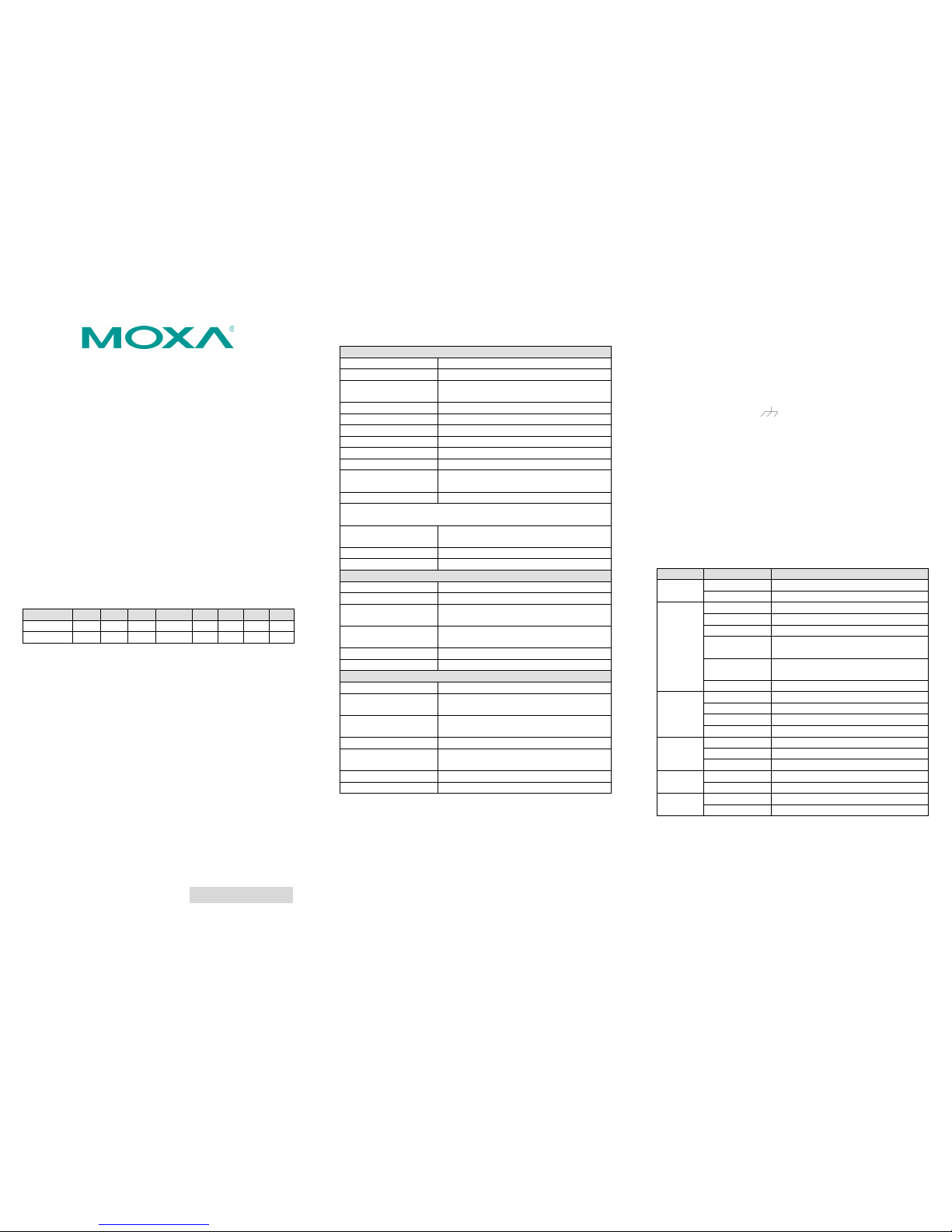
P/N: 1802015000011
ioLogik E1500 Series
Quick Installation Guide
Second Edition, February 2015
Overview
With a threaded M12 Ethernet port to ensure wired connectivity, a
spring-type terminal block for vibration-resistant cabling, and a
DIN rail mount assembly, the io Logik E1500 ser ies is designe d to
withstand the severe vibrations experienced with rolling stock and
wayside applic ations. Car efully engine ered channe l-to-channel
isolation gives protection against cross-line power surges and
crosstalk, ensuring stable data communications. In addition, the
ioLogik E1500 is compliant with EN 50121-3- 2, EN 50121-4, and
essential sections of the EN 50155 standard (covering operating
temperature, power input voltage, electrical surges, ESD, and
vibration), all of which are required for electronic equipment used
on or around railway vehicles.
Model Selection
ioLogik
DI
DO
DIO
Relay
AI
AO
RTD
TC
E1510-T
12 – – – – – – – E1512-T
4 – 4 – – – –
–
Package Checklist
• 1 ioLogik E1500 series remote I/O product
• Documentation and software CD
• Quick installat ion guide (prin ted)
Specifications
System
Ethernet
10/100 Mbps, M12 connector
Protection
1.5 KV magnetic isolation
Protocols
Modbus/TCP, TCP/IP, UDP, DHCP, Bootp,
HTTP
Power Input
24 VDC nominal, 12 to 48 VDC
Wiring
I/O cable, max. 14 AWG
Dimensions
144 x 124 x 30 mm (5.67 x 4.88 x 1.18 in)
Weight
825 g
Operating Temperature
-40 to 85°C (-40 to 185°F)
Storage Temperature
-40 to 85°C (-40 to 185°F)
Ambient Relative
Humidity
5 to 95% (non-condensing)
Altitude:
Up to 2000 m
Note: Please contact Moxa if you require products guaranteed to
function properly at higher altitudes.
Standards and
Certification s
UL 508, EN 50155, EN 50121-3-2, EN
50121-4
Warranty Period
5 years
Details
See www.moxa.com/warranty
Digital Input
Sensor Type
NPN, PNP, and Dry contact
I/O Mode
DI or Event Counter
Dry Contact
• On: short to GND
• Off: open
Wet Contact • On: 0 to 3 VDC
• Off: 10 to 30 VDC
Isolation
3k VDC or 2k Vrms
Counter/Frequency
250 Hz, power off storage
Digital Output
I/O Mode
DO or Pulse Output
Pulse Wave
Width/Frequency
1 ms/500 Hz
Over-voltage
Protection
45 VDC
Over-current Protection
2.6 A (4 channels @ 650 mA)
Over-temper ature
Shutdown
175°C (typical) , 150°C (min.)
Current Rating
200 mA per channel
Isolation
3k VDC or 2k Vrms
Installation
Power and Networking
Connect the +12 to +48 VDC power line to th e ioLogik E150 0’s
terminal block V+ terminal, and connect the ground from the
power supply to the V- terminal. If an earth grou nd is available ,
connect the ground pin ( ).
Mounting and Cabling
The ioLogik E1500 can be used with both DIN rail and wall mounts.
When mounting on a DIN rail, release the bottom mou nting kit,
install the ioLo gik on the rail, and then restore the bottom
mounting kit to fix the ioLogik t o the rail. When using wall
mounting, release both the upper and bottom DIN rail kits.
The ioLogik E150 0 has an M12 Ethernet port for connecting either
a standard direct-Ethernet or crossover-Ethernet cable via a
locking M12 connector.
LED Indicators
Type
Color
Description
PWR
Green
System power in ON
Off
System power is OFF
RDY
Green
System is ready
Green Blinking
Located
Red
System Booting-up Error
Green/Red
Blinking
Safe Mode
Red Blinking
Firmware upgrade (LED flashes for 3
seconds then stays red until restart)
Off
System is not ready
LAN
Green
100 Mbps
Amber
10 Mbps
Blinking
Data Transmitting
Off
Ethernet Off
EXP
Green
Expansion Mode Ready
Red
Configuration Failure
Off
Stand-alone Mode
DI
Green
Channel ON
Off
Channel OFF
DIO
Green
Channel ON
Off
Channel OFF
Page 2
– 4 – – 5 – – 6 –
www.moxa.com/support
The Americas:
+1-714-528-6777 (toll-free: 1-888-669-2872)
Europe:
+49-89-3 70 03 99-0
Asia-Pacific:
+886-2-8919-1230
China:
+86-21-5258-9955 (toll-free: 800-820-5036)
2015 Moxa Inc., All R ights Res erved
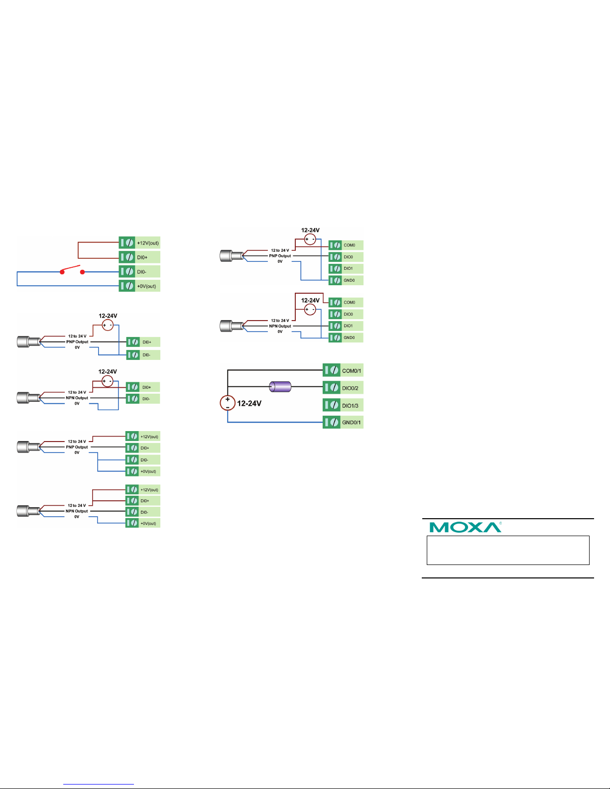
I/O Wiring
DI dry contact mode
DI wet contact mode (Ch-Ch isolation)
DI wet conta ct PNP/NPN mode (No CH-CH isolation)
DIO_DI wet contact mode (no CH-CH isolation)
DIO_DO sink mode
System Configuration
Configuration via Web Console
Configuration of an ioLogik E1500 is done via the web console.
• Default IP Address: 192.168.127.254
• Subnet Mask: 255.255.255.0
Note: Be sure to configure the host PC’s IP address to the same
subnet as the ioLogik E1500. For example, 192.168.127.253.
ioSearch Utility
ioSearch is a search utility that helps users locate an ioLogik E150 0
on the local network. The utility can be found in the Documentation
and Software C D under Softwar e ioSe arch; the latest version
can be downloaded from Moxa’s websit e.
Load Factory Default Settings
There are three ways to restore the ioLogik E1500 to the factory
default settings.
1. Remove the two screws and the aluminum plate, and then
press and hold the RES ET butt on for 5 sec onds.
2. Right click the specified ioLog ik in the ioSea rch utility and
select Reset to Default.
3. Select Load Factory Default from the web console.
Modbus Address Table
Refer to the user’s manual for details of the ioLogik’s Modbus
address, or refer to the start address of the I/O channels in the
web console under User-defined Modbus Addressing Default
Address.
Active OPC Server Conn ection
Take the following steps to connect the ioLogik E1500 to an Active
OPC Server:
1. Disable the user-defined Modbus address function.
2. Install the Active OPC Server Lite Package from the
Documention and Software CD under Software AOPC Lite
ActiveOPCSetup Install. exe.
3. Install from the Web console under Active OPC Server Settings
AOPC & I/O Settings . and specify the IP address of the
Active OPC Server. Specify the I/O channels that need to be
added to Active OPC Server Lite, submit the settings, and then
click Save/Restart.
4. From the web console under Active OPC Serve r Settings
Create AOPC Tag, click the “Create Tag” button.
5. Launch Active OPC Server Lite from Start Programs MOXA
IOServer ActiveOPC ActiveOPC. Save the configuration
before exiting the Active OPC Server Lite program.
 Loading...