

Page 1
– 1 – – 2 – – 3 –
P/N: 1802015000010
ioLogik E1500 Series
Quick Installation Guide
First Edition, May 2012
1. Overview
Boasting a threaded M12 Ethernet port to ensure wired
connectivity, a spring-type terminal block f or vibration- resistant
cabling, and a soundly convenient DIN rail mounting assembly ,
the ioLogik E1500 series is designe d to easily withsta nd the severe
vibrations experienced on rolling stock an d waysides. C arefully
engineered channel-to-channel isolation gives protection against
cross-line power surges and crosstalk, safeguarding stable data
communications. In addition, this remote I/O is compliant with EN
50121-3-2, EN 50121-4 and the essential sections of the EN 50155
standard (covering operating temperature, power input voltage,
electrical surges, ESD and vibration), all of which are fundamental
for any electronic equipment used on or around railway vehicles.
Model Selection:
ioLogik
DI
DO
DIO
Relay
AI
AO
RTD
TC
E1510-T
12 – – – – – –
–
E1512-T
4 – 4 – – – –
–
Package Checklist
• 1 ioLogik E1500 series remote I/O product
• Documentation and software CD
• Quick installat ion guide (prin ted)
2. Specifications
System
Ethernet: 10/100 Mbps, M12 connector
Protection: 1.5 KV magnetic isolation
Protocols: Modbus/TCP, TCP/IP, UDP, DHCP, Bootp,
HTTP
Power Input:
24 VDC nomin al, 12 to 48 VDC
Wiring:
I/O cable max. 14 AWG
Dimensions:
144 x 124 x 30 mm (5.67 x 4.88 x 1.18 in)
Weight:
825 g
Operating
Temperature:
Standard Models: -40 to 85°C (-40 to
185°F)
Storage Temperature: -40 to 85°C (-40 to 185°F)
Ambient Relative
Humidity:
5 to 95% (non-condensing)
Standards and
Certification s:
UL 508, EN50155, EN50121-3-2,
EN50121-4 (pending)
Warranty Period:
5 years
Details:
See www.moxa.com/warranty
Digital Input
Sensor Type:
NPN, PNP, and Dry contact
I/O Mode:
DI or Event Counter
Dry Contact:
• On: short to GND
• Off: open
Wet Contact:
• On: 0 to 3 VDC
• Off: 10 to 30 VDC
Isolation:
3K VDC or 2K Vrms
Counter/Frequency:
250 Hz, power off storage
Digital Output
I/O Mode:
DO or Pulse Output
Pulse Wave
Width/Frequency:
1 ms/500 Hz
Over-voltage
Protection:
45 VDC
Over-current
Protection:
2.6 A (4 channels @650 mA)
Over-temper ature
Shutdown:
175°C (typical) , 150°C (min.)
Current Rating:
200 mA per channel
Isolation:
3K VDC or 2K Vrms
3. Installation
Power and Netwo rking
Connect the +12 to +48 VDC po wer line to the ioLogik E1500’s
terminal block V+ terminal; connect the ground from the power
supply to the V- terminal. If an earth ground is av ailable, then
connect the ground pin ( ).
Mounting and Cabling
The ioLogik E1500 can be used with both DIN rail and wall mounts.
When mounting on a rail, release the bottom mounting kit, install
the ioLogik on the rail, and then restore the bottom mounting kit to
fix the ioLogik to the rail. When using wall mounting, release bo th
the upper and bottom DIN rail kits.
The ioLogik E1500 has an M12 Ethernet port for connecting either
a standard direct- or crossover-Ethernet cable via a locking M12
connector .
LED Indicators
Type
Color
Description
PWR
Green
System power in ON
Off
System power is OFF
RDY
Green
System is ready
Green
Blinking
Located
Red System Booting-up Error
Green/Red
Blinking
Safe Mode
Red
Blinking
Firmware upgrade (LED flashes for 3
seconds then stays Red until restart )
Off System is not ready
LAN Green 100Mb
Amber 10Mb
Blinking Data Transmitting
Off Ethernet Off
EXP Green Expansion Mode Ready
Red Configuration Fail
Off Stand-alone Mode
DIO Green Channel ON
Red Diagnostic Error
Off
Channel OFF
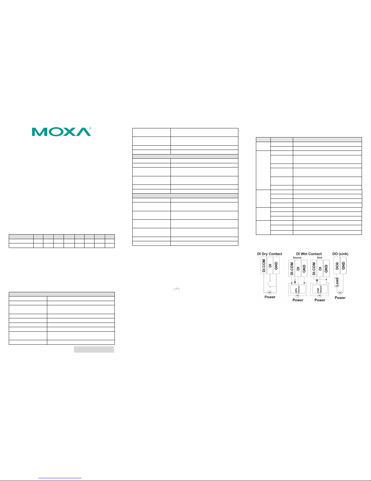
4. I/O Wiring
Digital Input/Output (Sink Type)
5. System Configuration
Configuration via Web Console
Main configuration of an ioLogik E1500 is via its web console.
• Default IP Address: 192.168.127.254
• Subnet Mask: 255.255.255.0
Note: Be sure to configure the host PC’s IP address to the same
subnet as the ioLogik E1500. For example, 192.168.127.253
Page 2

– 4 – – 5 – – 6 –
www.moxa.com/support
The Americas:
+1-714-528-6777 (toll-free: 1-888-669-2872)
Europe:
+49-89-3 70 03 99-0
Asia-Pacific:
+886-2-8919-1230
China:
+86-21-5258-9955 (toll-free: 800-820-5036)
2011 Moxa Inc., All Rig hts Reser ved
ioSearch Utility
ioSearch is a search utility that helps users locate an ioLogik E1500
on the local network. The utility can be found in the Document and
Software CD Software ioSearch; the latest version can be
downloaded from Moxa’s website.
Load Factory Default Settings
There are three ways to restore the ioLogik E1500 to the factory
default settings.
1. Hold the RESET button for 5 seconds.
2. Rig ht click the spe cified ioLogik in the ioSear ch utility and
select “Reset to Default.”
3. Select “Load Factory Default” from the web console.
Modbus Address Table
Please refer to the user’s manu al for details of t he ioLogik’s
Modbus address, or refer to the start address of the I/O channels in
web console User-defined Modbus Addressing Default
Address.
Active OPC Server Connect ion
Take the following steps to connect the ioLogik E1500 to an Active
OPC Server:
1. Disable the user-defined Modbus address function.
2. Install the Active OPC Server Lite Package from Document and
Software CD Software AOPC Lite ActiveOPCSe tup
Install.exe
3. In stall from Web console Active OPC Server Settings
AOPC & I/O Settings; specify the IP address where the Active
OPC Server is insta lled. Specify th e I/O channels that need to
be added t o Active OPC Server Lite. Submit the settings and
then Save/Rest art.
4. Fro m web console Active OPC Serv er Settings Create
AOPC Tag, click t he “Create Tag” button.
5. Launch Active OPC Server Lite from Start Programs MOXA
IOServer ActiveOPC ActiveOPC. Save the configuration
before exiting the Active OPC Server Lite program.
 Loading...