

Moxa Technologies ioLogik E1213, ioLogik E1212, ioLogik E1214, ioLogik E1210, ioLogik E1240 User Manual
...Page 1

ioLogik E1200 Series User’s Manual
Edition 15.4, October 2018
www.moxa.com/product
© 2018 Moxa Inc. All rights reserved.
Page 2

ioLogik E1200 Series User’s Manual
Moxa Americas
Toll
Tel:
Fax:
Moxa China (Shanghai office)
Toll
Tel:
Fax:
Moxa Europe
Tel:
Fax: +49-89-3 70 03 99-99
Mo
Tel:
Fax: +886-2-8919-1231
Moxa India
Tel:
Fax:
The software described in this manual is furnished under a license agreement and may be used only in accordance with
the terms of that agreement.
Copyright Notice
© 2018 Moxa Inc. All rights reserved.
Trademarks
The MOXA logo is a registered trademark of Moxa Inc.
All other trademarks or registered marks in this manual belong to their respective manufacturers.
Disclaimer
Information in this document is subject to change without notice and does not represent a commitment on the part of
Moxa.
Moxa provides this document as is, without warranty of any kind, either expressed or implied, including, but not limited
to, its particular purpose. Moxa reserves the right to make improvements and/or changes to this manual, or to the
products and/or the programs described in this manual, at any time.
Information provided in this manual is intended to be accurate and reliable. However, Moxa assumes no responsibility for
its use, or for any infringements on the rights of third parties that may result from its use.
This product might include unintentional technical or typographical errors. Changes are periodically made to the
information herein to correct such errors, and these changes are incorporated into new editions of the publication.
Technical Support Contact Information
www.moxa.com/support
-free: 1-888-669-2872
+1-714-528-6777
+1-714-528-6778
+49-89-3 70 03 99-0
-free: 800-820-5036
+86-21-5258-9955
+86-21-5258-5505
xa Asia-Pacific
+886-2-8919-1230
+91-80-4172-9088
+91-80-4132-1045
Page 3

Table of Contents
1. Introduction ...................................................................................................................................... 1-1
Product Features ................................................................................................................................ 1-2
Inside the Box .................................................................................................................................... 1-2
Product Model Information ................................................................................................................... 1-2
Product Specifications ......................................................................................................................... 1-3
Physical Dimensions ............................................................................................................................ 1-3
Hardware Reference ............................................................................................................................ 1-4
Panel Guide ................................................................................................................................ 1-4
Ethernet Port .............................................................................................................................. 1-4
LED Indicators ............................................................................................................................ 1-4
I/O Circuit Diagram ............................................................................................................................. 1-5
DI Circuit ................................................................................................................................... 1-5
Sinking DO Circuit ....................................................................................................................... 1-5
Sourcing DO Circuit ..................................................................................................................... 1-6
DIO Circuit ................................................................................................................................. 1-7
Relay Circuit ............................................................................................................................... 1-8
AI Circuit .................................................................................................................................... 1-8
RTD Circuit ................................................................................................................................. 1-8
TC Circuit ................................................................................................................................... 1-9
2. Initial Setup ...................................................................................................................................... 2-1
Hardware Installation .......................................................................................................................... 2-2
Mounting .................................................................................................................................... 2-2
Grounding the Unit ...................................................................................................................... 2-4
I/O Channel Jumper Setting.......................................................................................................... 2-4
I/O Wiring .................................................................................................................................. 2-6
Communication Port Wiring ........................................................................................................ 2-10
Use the Cable Tie Base to Securely Route a Connected I/O Cable .................................................... 2-11
Powering Up the Unit ................................................................................................................. 2-11
ioSearch™ Installation ....................................................................................................................... 2-13
Load Factory Default Settings ............................................................................................................. 2-13
3. Using the Web Console ...................................................................................................................... 3-1
Introduction to the Web Console ........................................................................................................... 3-2
Overview ........................................................................................................................................... 3-3
Network Settings for the Web Console ................................................................................................... 3-4
General Settings ......................................................................................................................... 3-4
Ethernet Configuration ................................................................................................................. 3-4
User-Defined Modbus Addressing .......................................................................................................... 3-5
Default Modbus Address ............................................................................................................... 3-5
AOPC Server Settings .......................................................................................................................... 3-6
Tag Generation ........................................................................................................................... 3-6
I/O Settings ....................................................................................................................................... 3-8
DI Channels ................................................................................................................................ 3-8
DO Channels ............................................................................................................................. 3-10
AI Channels .............................................................................................................................. 3-12
AI Input Range ......................................................................................................................... 3-13
AO Channels ............................................................................................................................. 3-15
RTD Channels ........................................................................................................................... 3-16
TC Channels ............................................................................................................................. 3-17
Peer-to-Peer Networking.................................................................................................................... 3-19
Peer-to-Peer Settings (1-50)....................................................................................................... 3-19
Sample Peer-to-Peer Configuration .............................................................................................. 3-20
DO Safe Mode Settings .............................................................................................................. 3-21
AO Safe Mode Settings ............................................................................................................... 3-21
SNMP .............................................................................................................................................. 3-21
SNMP Trap ............................................................................................................................... 3-21
Using SNMP .............................................................................................................................. 3-22
Accessibility IP List .................................................................................................................... 3-27
RESTful API Setting........................................................................................................................... 3-28
EtherNet/IP Setting ........................................................................................................................... 3-28
System Management ......................................................................................................................... 3-28
Network Connection................................................................................................................... 3-28
Firmware Update ....................................................................................................................... 3-29
Import System Configuration Settings ......................................................................................... 3-29
Export System Settings .............................................................................................................. 3-29
Change Password ............................................................................................................................. 3-30
Load Factory Defaults ........................................................................................................................ 3-30
Save/Restart .................................................................................................................................... 3-30
Page 4

4. Using ioSearch™ ................................................................................................................................ 4-1
Introduction to ioSearch™ ................................................................................................................... 4-2
ioSearch™ Main Screen ....................................................................................................................... 4-2
Main Screen Overview .................................................................................................................. 4-2
ioSearch™ Setup ................................................................................................................................ 4-3
System ...................................................................................................................................... 4-3
Sort ........................................................................................................................................... 4-4
Quick Links ................................................................................................................................. 4-4
Main Function ..................................................................................................................................... 4-4
Locate ........................................................................................................................................ 4-5
Firmware Upgrade ....................................................................................................................... 4-5
Unlock ....................................................................................................................................... 4-6
Import ....................................................................................................................................... 4-6
Export ........................................................................................................................................ 4-6
Change IP Address ...................................................................................................................... 4-7
Batch TCP/IP Configuration on Multiple Devices ............................................................................... 4-7
Change Server Name ................................................................................................................... 4-8
Activate EtherNet/IP .................................................................................................................... 4-8
Restart System ........................................................................................................................... 4-9
Reset to Default .......................................................................................................................... 4-9
Mass Deployment (Import) ........................................................................................................... 4-9
Mass Deployment (Export) ......................................................................................................... 4-10
5. Activating the EtherNet/IP Function ................................................................................................. 5-1
6. How to Connect the ioLogik E1200 to an Allen-Bradley PLC .............................................................. 6-1
EDS Installation of the ioLogik E1200 Series in Rockwell Software RSLogix 5000 ........................................ 6-2
Establishing communication between the ioLogik E1200 device and the Allen-Bradley PLC ........................... 6-6
7. RESTful API Implementation ............................................................................................................. 7-1
Introduction ....................................................................................................................................... 7-2
Configuring RESTful API Settings .......................................................................................................... 7-2
Using RESTful API via a Web Service ..................................................................................................... 7-2
Troubleshooting Reference ................................................................................................................... 7-5
A. Modbus/TCP Default Address Mappings ............................................................................................ A-1
Supported Function Code ..................................................................................................................... A-2
ioLogik E1210 Modbus Address and Register Map ................................................................................... A-2
ioLogik E1211 Modbus Address and Register Map ................................................................................... A-3
ioLogik E1212 Modbus Address and Register Map ................................................................................... A-5
ioLogik E1213 Modbus Address and Register Map ................................................................................... A-7
ioLogik E1214 Modbus Address and Register Map ................................................................................... A-9
ioLogik E1240 Modbus Address and Register Map ................................................................................. A-11
ioLogik E1241 Modbus Address and Register Map ................................................................................. A-12
ioLogik E1242 Modbus Address and Register Map ................................................................................. A-14
ioLogik E1260 Modbus Address and Register Map ................................................................................. A-16
ioLogik E1262 Modbus Address and Register Map ................................................................................. A-18
B. EtherNet/IP Default Address Mappings............................................................................................. B-1
ioLogik E1200 EtherNet/IP Map ............................................................................................................ B-1
C. RESTful API Default Address Mappings ............................................................................................. C-1
ioLogik E1200 RESTful API Map ............................................................................................................ C-1
D. Network Port Numbers ...................................................................................................................... D-1
E. Factory Default Settings .................................................................................................................... E-1
F. Pinouts .............................................................................................................................................. F-1
G. FCC Interference Statement .............................................................................................................. G-1
H. European Community (CE) ................................................................................................................ H-1
I. Firmware Update Guidelines .............................................................................................................. I-1
Page 5

1
1. Introduction
The ioLogik E1200 industrial Ethernet remote I/O has two embedded Ethernet switch ports that allow
information to flow to another local Ethernet device or connect to the next ioLogik in a daisy-chain. Applications
such as factory automation, security and surveillance systems, and tunnel monitoring, can make use of
daisy-chained Ethernet for building multidrop I/O networks over standard Ethernet cables and familiar fieldbus
protocols. The daisy-chain function on the ioLogik E1200 Ethernet remote I/O not only increases the
connections between machines and panels, but it also lowers the cost of buying separate Ethernet switches,
and at the same time reduces labor fees and cabling by a large percentage. For example, if a production facility
contains 700 stations (20 points per station), the wiring cost reduction can reach 15% of the total
implementation cost.
The following topics are covered in this chapter:
Product Features
Inside the Box
Product Model Information
Product Specifications
Physical Dimensions
Hardware Reference
Panel Guide
Ethernet Port
LED Indicators
I/O Circuit Diagram
DI Circuit
Sinking DO Circuit
Sourcing DO Circuit
DIO Circuit
Relay Circuit
AI Circuit
RTD Circuit
TC Circuit
Page 6

ioLogik E1200 Series Introduction
1-2
NOTE
Notify your sales representative if any of the above items are missing or damaged.
ioLogik E1212
Remote Ethernet I/O with 2-port Ethernet switch, 8 DIs, and 8 DIOs
Ethernet remote I/O with 2-port Ethernet switch and 16 DIs, -40 to 75°C operating
temperature
temperature
Ethernet remote I/O with 2-port Ethernet switch, 8 DIs, and 8 DIOs, -40 to 75°C
operating temperature
type), -40 to 75°C operating temperature
Ethernet remote I/O with 2-port Ethernet switch, 6 DIs, and 6 Relays, -40 to 75°C
operating temperature
temperature
Ethernet remote I/O with 2-port Ethernet switch and 4 AOs , -40 to 75°C operating
temperature
40 to 75°C
operating temperature
Ethernet remote I/O with 2-port Ethernet switch and 6 RTDs, -40 to 75°C operating
temperature
temperature
Product Features
• Active communication with patented MX-AOPC UA Server
• 2-port Ethernet switch for daisy-chain topologies
• Easy mass deployment and configuration with ioSearch™utility
• User-friendly configuration via web browser
• Save time and wiring costs with peer-to-peer communication
• User-defined Modbus/TCP addressing
• Simplify I/O management with MXIO library on either Windows or Linux platform
• Wide operating temperature: -40 to 75°C (-40 to 167°F)
• Supports SNMPv1/v2c
• UL/cUL Class I Division 2, ATEX Zone 2 certification
Inside the Box
The ioLogik E1200 is shipped with the following items:
• ioLogik E1200 remote Ethernet I/O server
• Quick installation guide (printed)
Product Model Information
Model Description
ioLogik E1210 Remote Ethernet I/O with 2-port Ethernet switch and 16 DIs
ioLogik E1211 Remote Ethernet I/O with 2-port Ethernet switch and 16 DOs
ioLogik E1213 Remote Ethernet I/O with 2-port Ethernet switch, 8 DIs, 4 DOs, and 4 DIOs (source type)
ioLogik E1214 Remote Ethernet I/O with 2-port Ethernet switch, 6 DIs, and 6 relays
ioLogik E1240 Remote Ethernet I/O with 2-port Ethernet switch and 8 AIs
ioLogik E1241 Remote Ethernet I/O with 2-port Ethernet switch and 4 AOs
ioLogik E1242 Remote Ethernet I/O with 2-port Ethernet switch and 4 AIs, 4DIs, and 4DIOs
ioLogik E1260 Remote Ethernet I/O with 2-port Ethernet switch and 6 RTDs
ioLogik E1262 Remote Ethernet I/O with 2-port Ethernet switch and 8 TCs
ioLogik E1210-T
ioLogik E1211-T
ioLogik E1212-T
ioLogik E1213-T
Ethernet remote I/O with 2-port Ethernet switch and 16 DOs, -40 to 75°C operating
Remote Ethernet I/O with 2 Port Ethernet switch, 8 DIs, 4 DOs, and 4 DIOs (source
ioLogik E1214-T
ioLogik E1240-T
ioLogik E1241-T
ioLogik E1242-T
ioLogik E1260-T
ioLogik E1262-T
Ethernet remote I/O with 2-port Ethernet switch and 8 AIs, -40 to 75°C operating
Ethernet remote I/O with 2-port Ethernet switch, 4 AIs, 4 DIs, and 4 DIOs, -
Ethernet remote I/O with 2-port Ethernet switch and 8 TCs, -40 to 75°C operating
Page 7
ioLogik E1200 Series Introduction
1-3
NOTE
The latest specifications for Moxa’s products can be found at
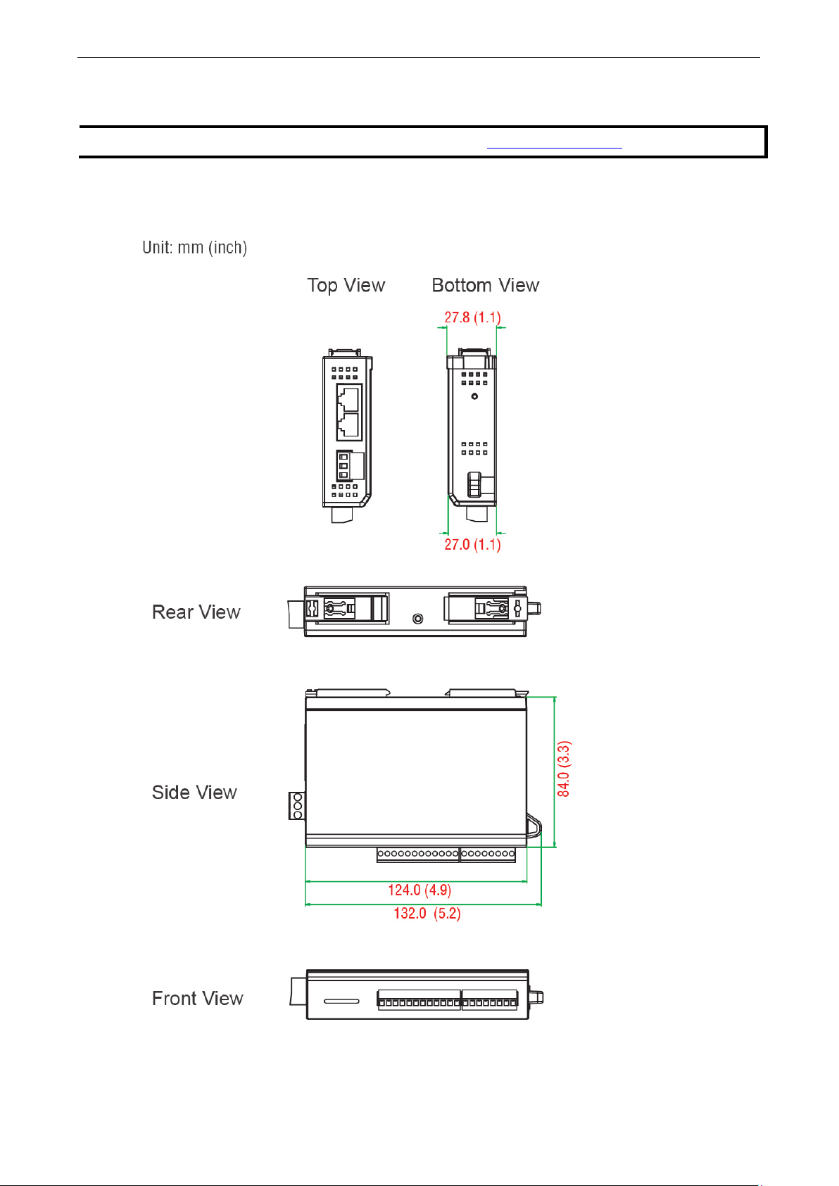
Product Specifications
Physical Dimensions
https://www.moxa.com.
Page 8
ioLogik E1200 Series Introduction
1-4
NOTE
The RESET button restarts the server and resets all settings to factory defaults. Use a pointed object such as
a straightened paper clip to hold down the RESET button for 5 seconds. The factory defaults will be loaded once
the READY LED turns green again. You
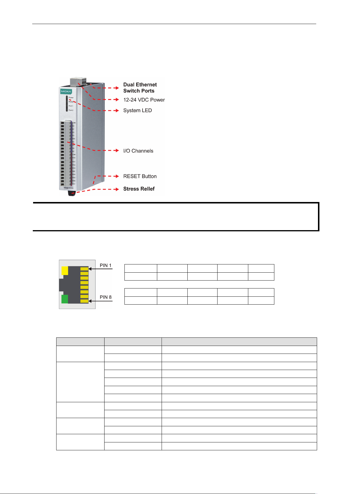
Hardware Reference
Panel Guide
Ethernet Port
LED Indicators
LED State Description
Power Amber System power is ON
Ready Green System is ready
Port 1 Green Ethernet connection enabled
Port 2 Green Ethernet connection enabled
EXT Green EXT field power input is connected
may then release the RESET button.
Pin 1 2 3 4
Signal TXD+ TXD- RXD+ ---
Pin 5 6 7 8
Signal --- RXD- --- ---
OFF System power is OFF
Flashing Flashes every 1 second when the “Locate” function is triggered
Flashing Flashes every 0.5 second when the firmware is being upgraded
Flashing ON/OFF cycle period of 0.5 second represents “Safe Mode”
OFF System is not ready
Flashing Transmitting or receiving data
Flashing Transmitting or receiving data
Off EXT field power input is disconnected
Page 9

ioLogik E1200 Series Introduction
1-5
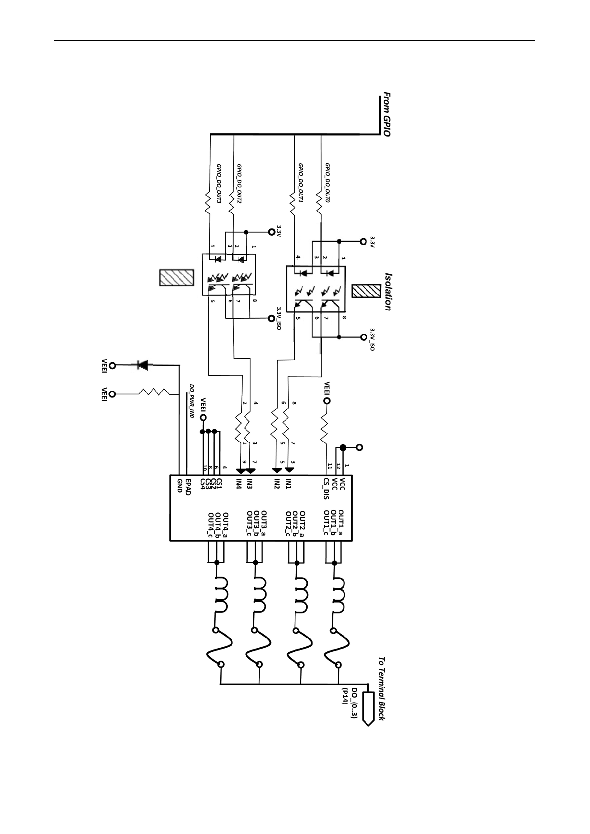
I/O Circuit Diagram
DI Circuit
Sinking DO Circuit
Page 10
ioLogik E1200 Series Introduction
1-6
Sourcing DO Circuit
Page 11
ioLogik E1200 Series Introduction
1-7
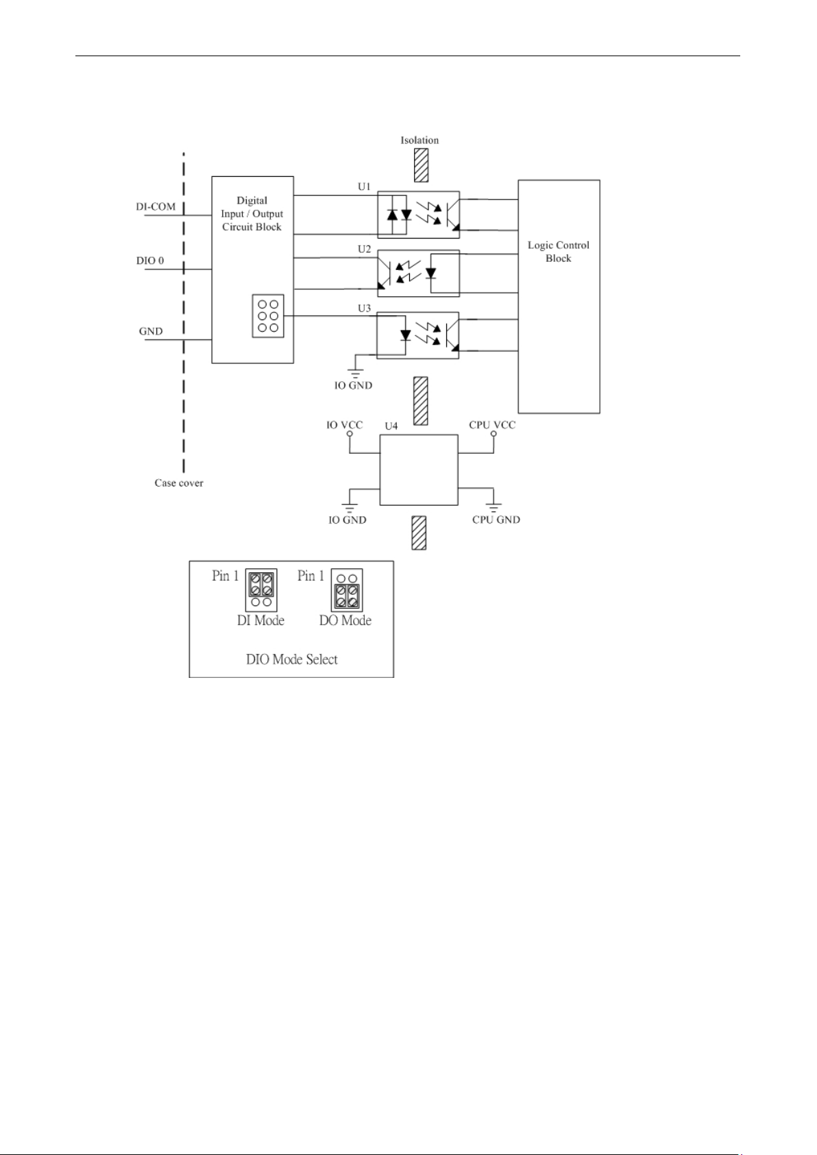
DIO Circuit
Page 12
ioLogik E1200 Series Introduction
1-8
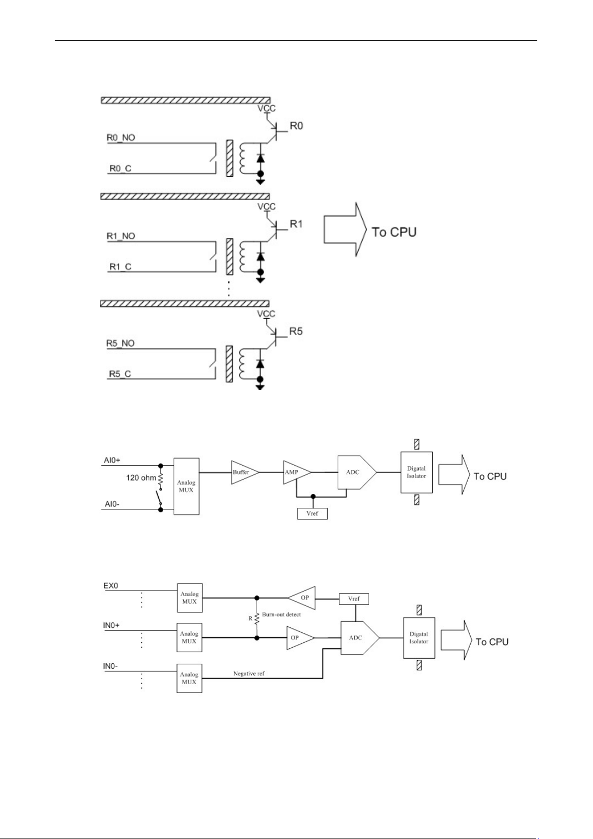
Relay Circuit
AI Circuit
RTD Circuit
Page 13

ioLogik E1200 Series Introduction
1-9
TC Circuit
Page 14

2
2. Initial Setup
This chapter describes how to install the ioLogik E1200.
The following topics are covered in this chapter:
Hardware Installation
Mounting
Grounding the Unit
I/O Channel Jumper Setting
I/O Wiring
Communication Port Wiring
Use the Cable Tie Base to Securely Route a Connected I/O Cable
Powering Up the Unit
ioSearch™ Installation
Load Factory Default Settings
Page 15

ioLogik E1200 Series Initial Setup
2-2
ATTENTION
This unit is sensitive to Electrostatic Discharge, which can cause internal damage and affect normal operation.
Follow the
•
•
•
•
•
•
WARNING
Disconnect
unless the
area is known to be free of ignitable
•
, an
sure
•
power is
•
STEP 1
Hardware Installation
Read all of the safety notifications and warnings below before installing the product.
Before handling the product, touch a grounded object to discharge static electricity from your body.
Wear an approved grounding wristband.
Do not touch connectors or pins on component boards.
Do not touch circuit components inside the equipment.
Use a static-safe workstation, if available.
Store the equipment in appropriate static-safe packaging when not in use.
If you connect or disconnect the Removable Terminal Block while field power is applied to the product
If you connect or disconnect wiring while the field-side power is applied to the product, an electrical arc
Do not disconnect the unit unless the power has been disconnected or the area is known to be
se guidelines when you handle this unit:
the power when you want to remove or replace components or disconnect equipment,
material.
electrical arc could occur. The arc could cause an explosion in hazardous location installations. Make
the power is disconnected, or the area is nonhazardous before starting the installation process.
could occur. The arc could cause an explosion in hazardous location installations. Make sure the
disconnected or the area is nonhazardous before starting the installation process.
nonhazardous. In a hazardous area, the unit must be powered down before removal.
Mounting
The unit supports two types of mounting: DIN-Rail Mounting and Wall Mounting. While mounting the unit, be
sure to use the correct tools and accessories to ensure that the unit is property mounted.
DIN Rail
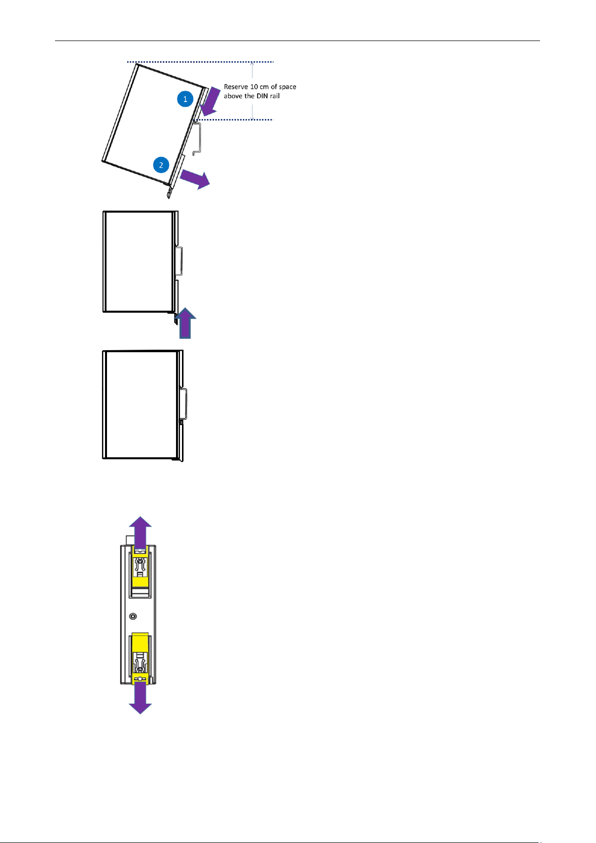
Take the following steps to mount the unit on a DIN rail:
. Pull down the bottom of the two sliders on the back of the unit.
Page 16
ioLogik E1200 Series Initial Setup
2-3
STEP 2
as
shown in the diagram.
above
that there is enough space to
complete the
STEP 3.
ush
the bottom slider
to lock the unit to
the DIN rail
STEP 4.
he unit
sh
STEP 1. There are two sliders
s out away from the
product
. Latch the top slider of the unit onto the DIN rail
Reserve at least 10 cm of space
the DIN rail to ensure
installation.
Rotate the unit down into a vertical position, and then p
back up to its original position
.
Wall Mounting
At this point, if the mounting was done correctly, t
ould be securely fixed to the DIN Rail.
on the back of the unit, pull out both slider
.
Page 17
ioLogik E1200 Series Initial Setup
2-4
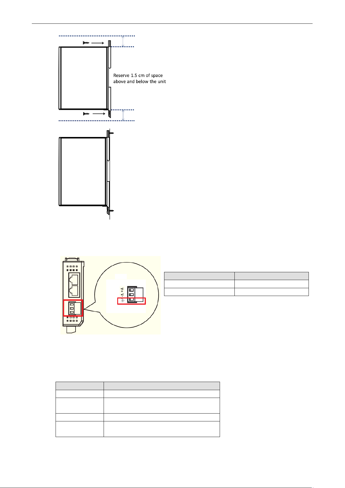
STEP 2. Use screws to fix the unit to the wall, as shown in the
diagram.
the unit to ensure
STEP 3.
securely
The ioLogik E1200
panel
the terminal block. Connect the ground pin ( ) to earth
ground.
Reserve at least 1.5 cm of space above and below
that the installation can be done correctly.
At this point, if the mounting was done correctly, the unit should be
fixed to the wall.
Grounding the Unit
Top View
I/O Channel Jumper Setting
The following table shows jumper setting for each model of the ioLogik E1200 Series. We provide a more
detailed description of three different jumper settings.
Model Jumper Setting
E1212 DIO direction (DI, DO)
E1213 1. DIO direction (DI, DO)
2. EXT Power Configuration
E1240 AI mode (Voltage, Current)
E1242 1. DIO direction (DI, DO)
2. AI mode (Voltage, Current)
has a grounding point located on the top
of
Item Suggested Setting
Wire range 12 to 24 AWG
Screw Torque 7 lb-inch
Page 18
ioLogik E1200 Series Initial Setup
2-5
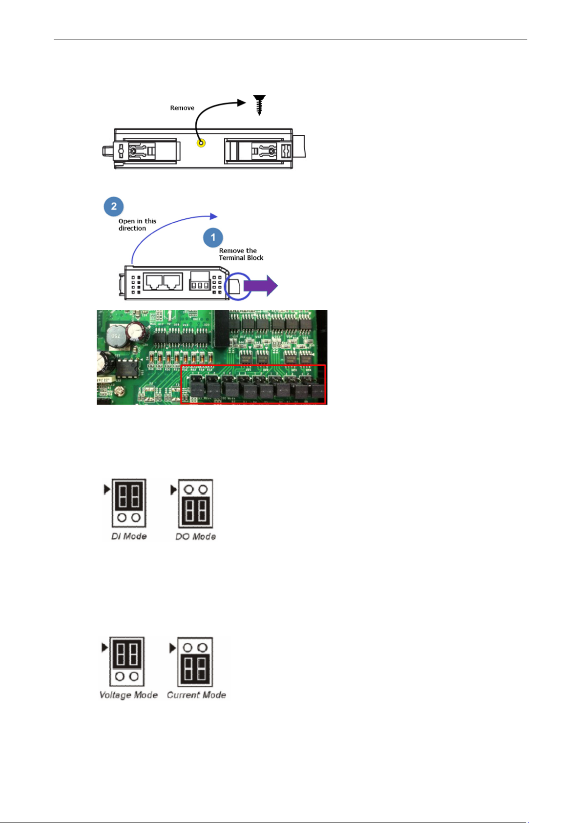
STEP 1. Remove the screw
(Suggested Torque: 3.9 ± 0.4 kg
STEP 2. Remove the Terminal Block and open the top cover as
shown in the diagram
STEP 3.
channels. Jumper settings for different modes of
operation are described below. In the diagrams,
a triangle is used to indicate the direction of the
setting.
Take the following to open up the unit.
Rear View
Top View
from the back panel.
-cm)
.
The jumpers are located near the IO
DIO Direction (DI, DO)
DIO mode configuration settings are shown below:
The default setting is DO Mode.
AI mode (Voltage, Current)
Analog mode configuration settings are shown below:
The default setting is Voltage Mode.
Page 19
ioLogik E1200 Series Initial Setup
2-6
Example:
If jumper is set to 12V,
EXT power will be 12V.
NOTE
The ioLogik E1213 has 4 pure DO channels and 4 hybrid DIO channels. For the 4 pure DO channels, you can use
the jumpers to select th
12 V, 9 V). But for the 4 hybrid DIO
channels, you cannot use the jumpers to select the power configuration output. Instead, you can only use the
jumpers to set the DIO channels to either DI mode or DO mode.
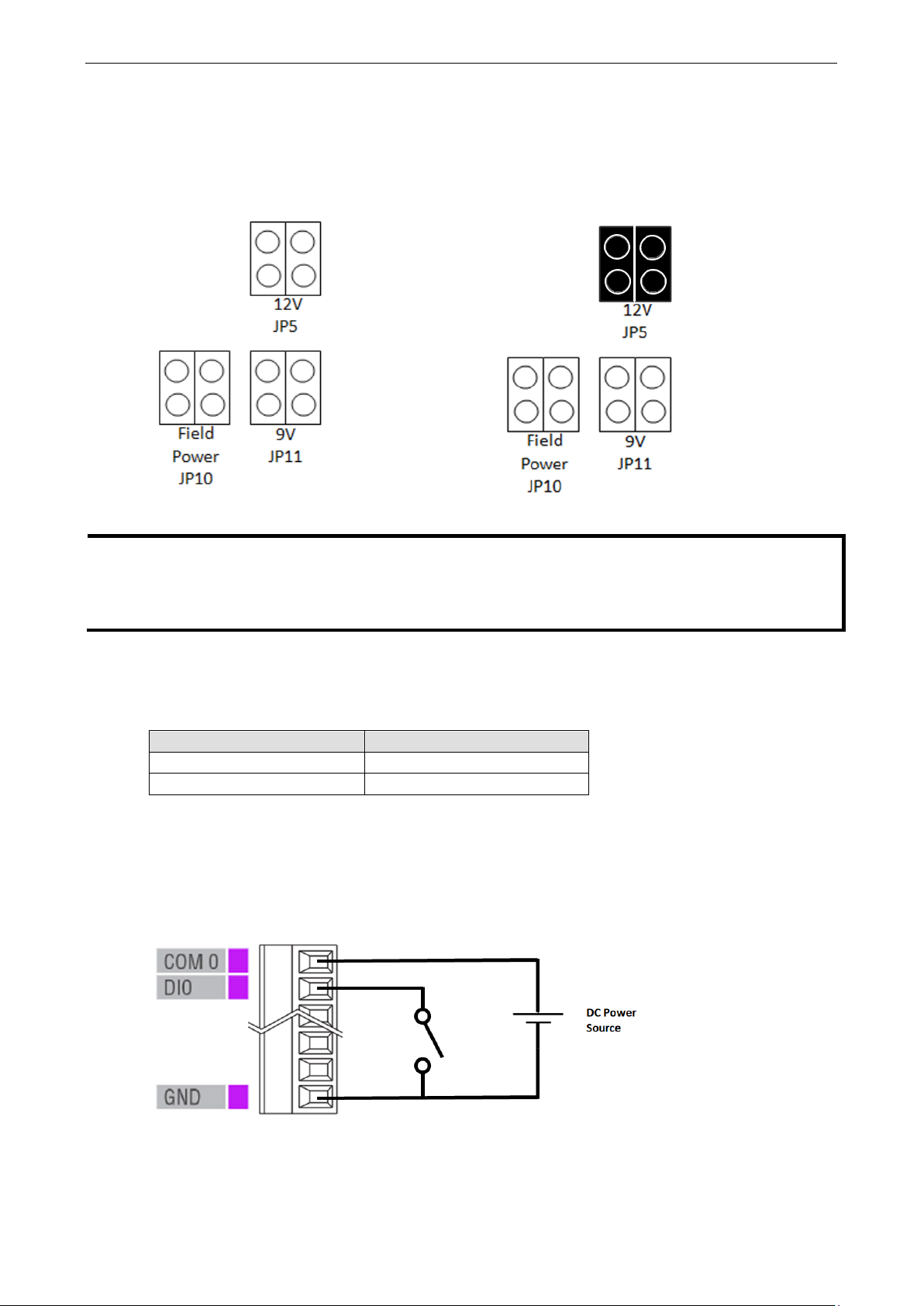
EXT Power Configuration
The ioLogik E1213 comes with a source type DO, which has three possible external (EXT) power configurations.
Only one field power configuration can be selected at a time (JP10 / 12V JP5 / 9V JP11), and the jumper must
be inserted vertically, not horizontally. EXT power configuration settings are shown below:
The default setting is Field Power JP10.
I/O Wiring
The following wiring guide explains how to configure seven different types of I/O channel:
Item Suggested Setting
Wire range 16 to 26 AWG
Screw Torque 3 lb-inch
A Dry Contact is a contact that works without a power source. This applies to buttons, switches, etc.
A Wet Contact is a contact that must be connected to a power source to work. This applies to proximity
sensors, motion sensors, etc.
Check the sensor type (NPN, PNP) and follow the corresponding wiring instructions.
DI Dry Contact
e power configuration output (e.g., field power:
Page 20
ioLogik E1200 Series Initial Setup
2-7
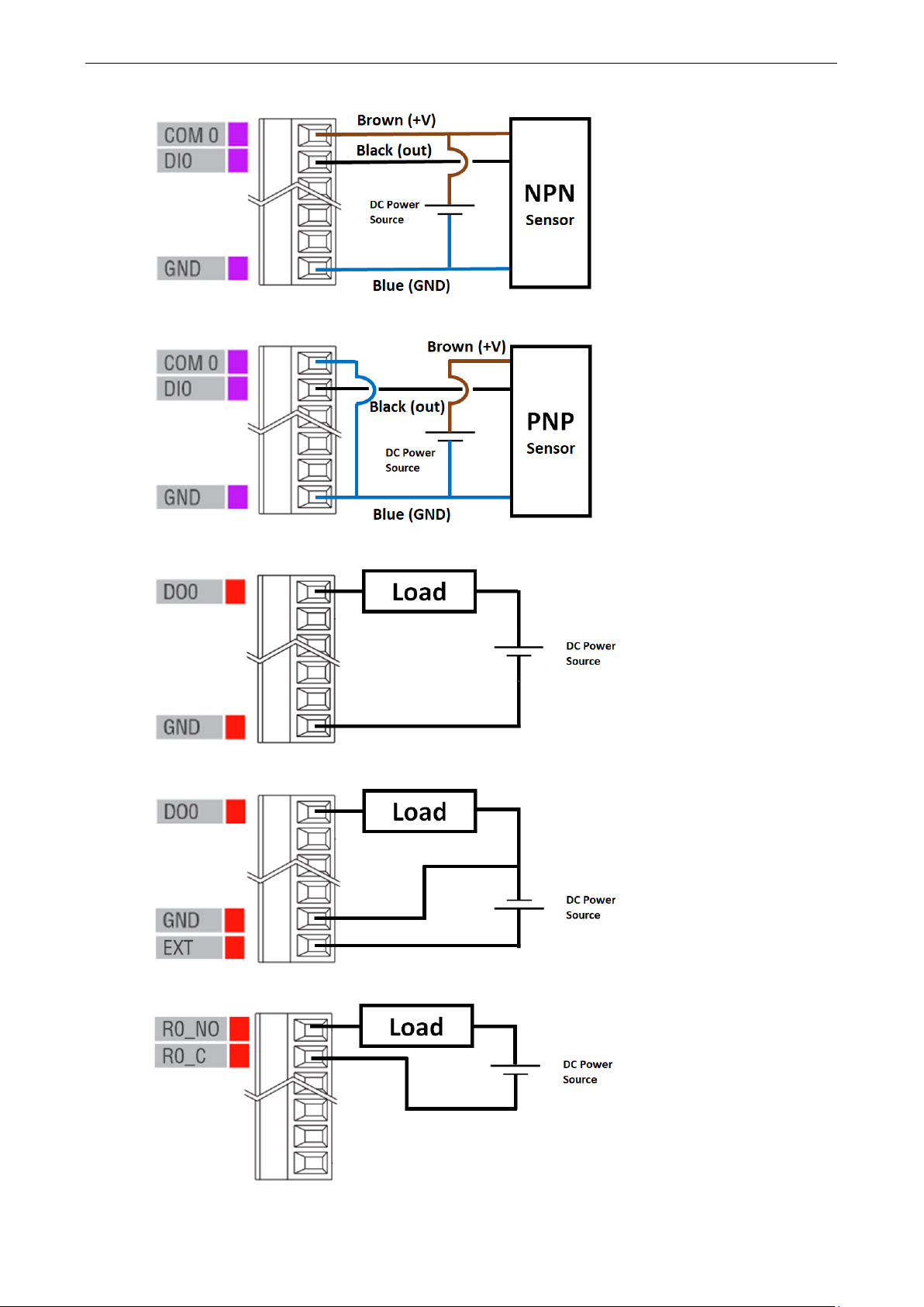
DI Wet Contact (NPN)
DI Wet Contact (PNP)
DO (Sink Type)
DO (Source Type)
Relay
Page 21
ioLogik E1200 Series Initial Setup
2-8
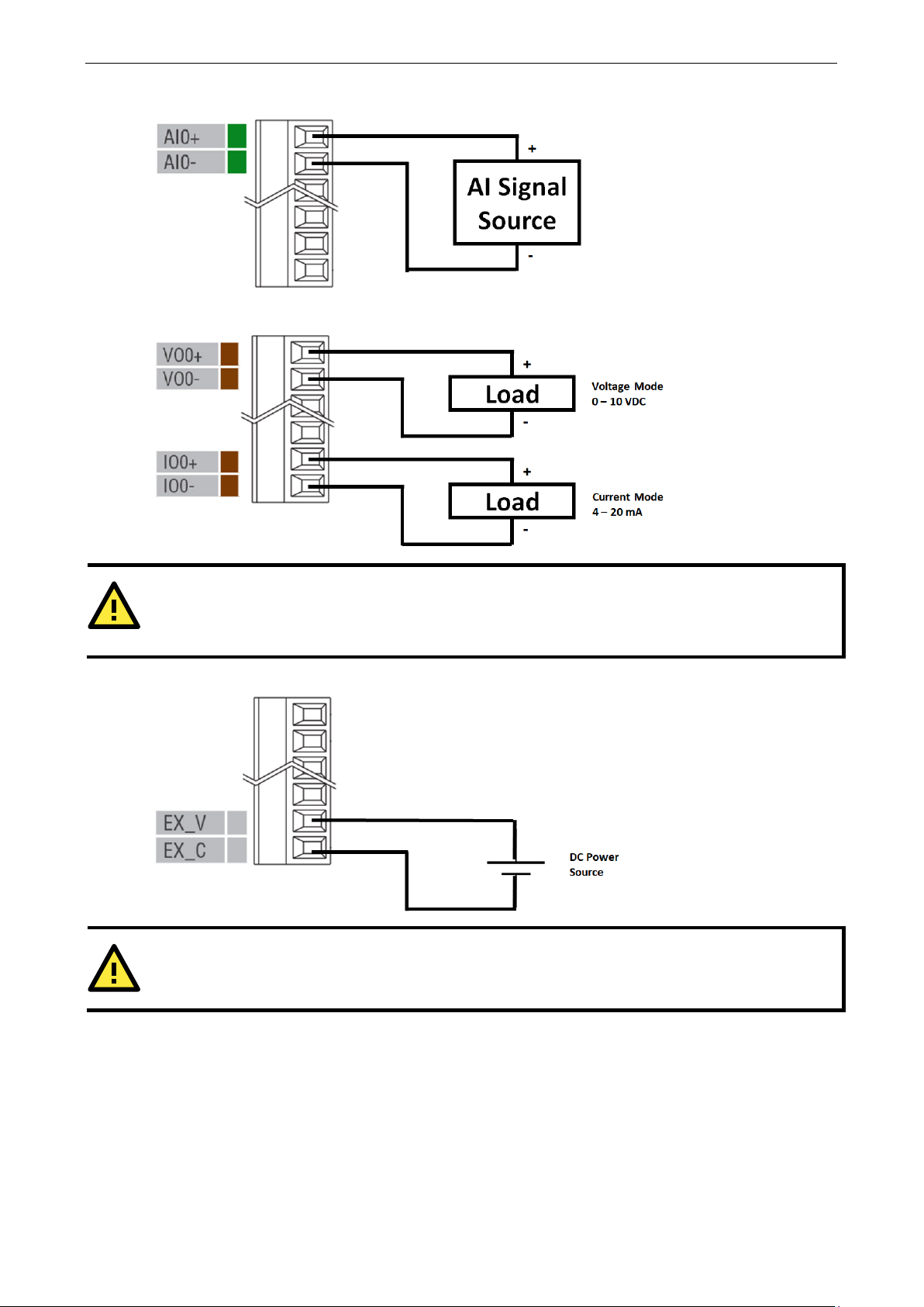
ATTENTION
Use
(
ATTENTION
24V of external power required in Analog output when loading exceeds 1000ohms.
AI
AO
the AO channel corresponding to the mode of operation you are using, as described above
e.g., voltage mode VO, current mode IO).
AO with external power
Page 22
ioLogik E1200 Series Initial Setup
2-9
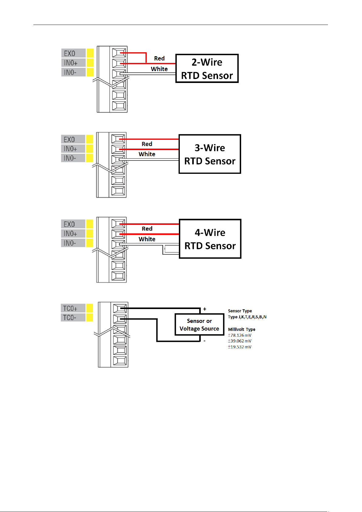
2-Wire RTD
3-Wire RTD
4-Wire RTD
TC
Page 23
ioLogik E1200 Series Initial Setup
2-10
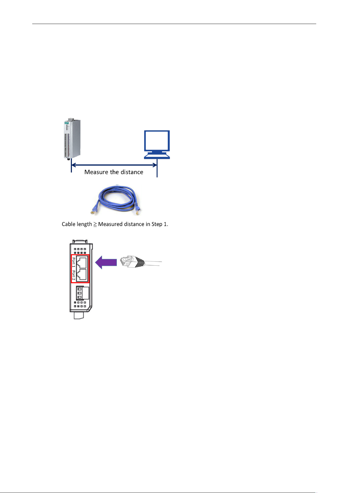
STEP 1. Measure the distance between the unit and your
workstation/ switch/ connected equipment.
STEP 2. Prepare
longer
than the distance m
STEP 3.
Port1/Port2.
Communication Port Wiring
The product series offers the communication ports described below:
RJ45: Ethernet
The Ethernet ports (Port1/Port2) on the unit are unmanaged switch ports. Each of the two ports function in
essentially the same way.
Take the following steps to wire the communication port correctly.
an Ethernet cable (RJ45 connector)
easured in Step 1.
Top View
Connect the RJ45 connector of the cable to
Page 24
ioLogik E1200 Series Initial Setup
2-11
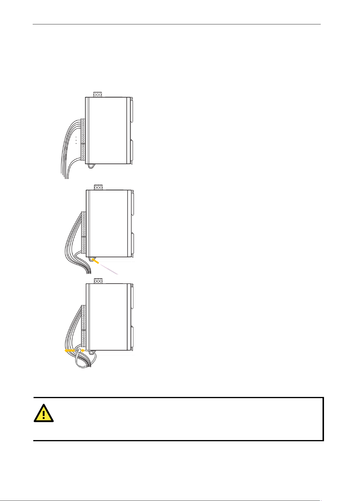
STEP 1.
STEP 2.
STEP 3. Fix the I/O channel cables to
WARNING
Confirm
power to the unit
operate in an
Use the Cable Tie Base to Securely Route a Connected I/O
Cable
The products in this series have a cable tie base at the bottom of the unit for securely routing connected I/O
cables, thereby decreasing the risk that the cable or terminal will be damaged accidentally.
Refer to the I/O wiring section to wire the I/O channel.
Insert the cable tie strap through the cable tie base.
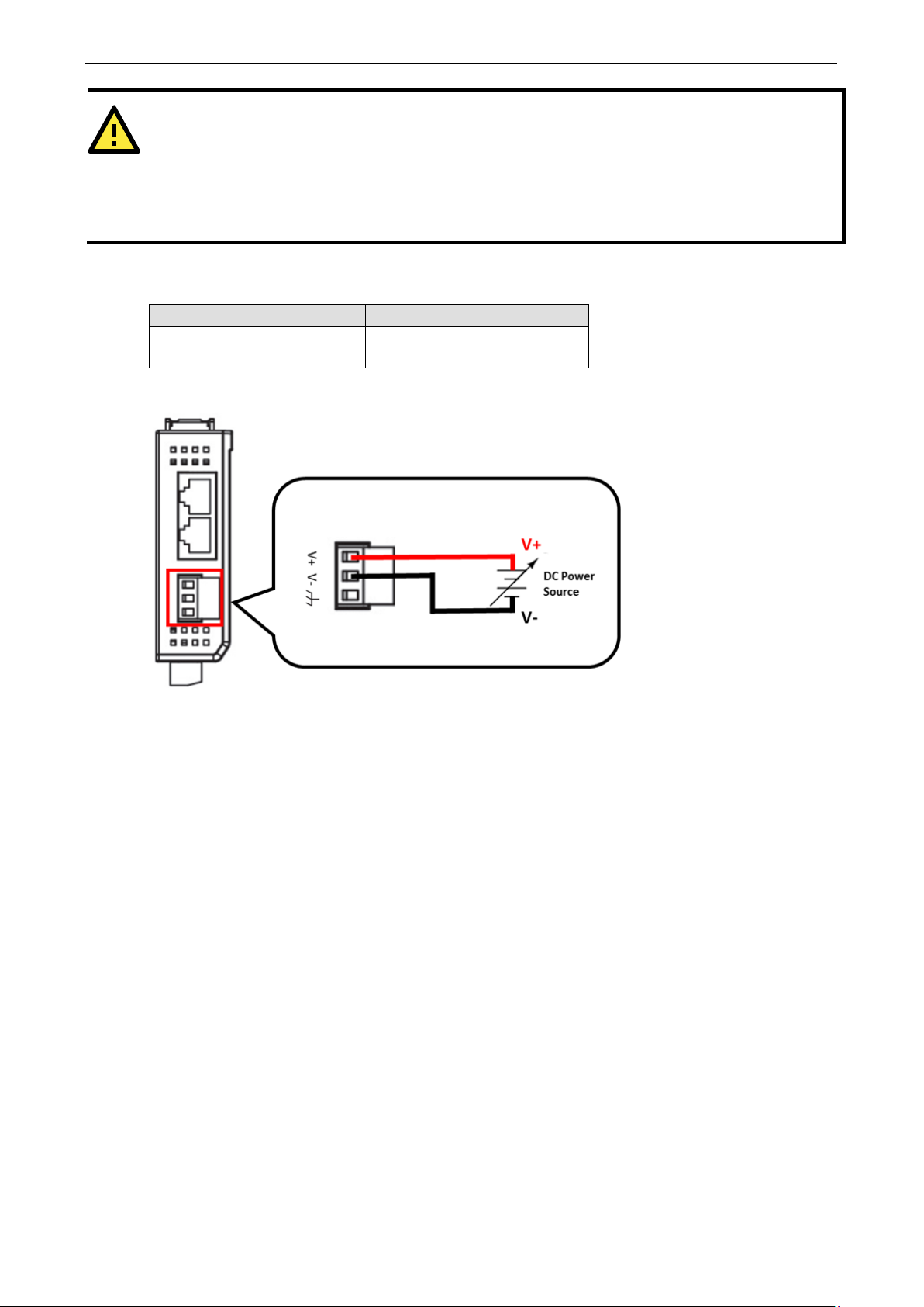
Powering Up the Unit
that the rated voltage of the connected DC Power Source is within 12 to 36 VDC to supply efficient
the cable tie base
; if the power source does not supply voltage in this range, your unit could be damaged or
unpredictable manner.
Page 25
ioLogik E1200 Series Initial Setup
2-12
ATTENTION
Determine the maximum possible current for each power wire and common wire according
maximum
causing serious damage to your equipment. For safety reasons, we recommend an average cable size of 22
AWG. However, depending on the current load, you may want to adjust your cable size (the maximum wire size
for power connectors is 2 mm).
The power terminal block is located on the top panel of the unit. Connect the unit to a 12 to 36 VDC power
source as shown below.
Item Suggested Setting
Wire range 12 to 24 AWG
Screw Torque 7 lb-inch
allowable current spec. If the current exceeds the maximum rating, the wiring may overheat,
Top View
to its size and
If power is properly supplied, the Power LED will glow a solid amber color. Continue to configure the software
after you have finished installing the hardware.
Page 26
ioLogik E1200 Series Initial Setup
2-13
ioSearch™ Installation
ioSearch™ is a search utility that helps the user locate ioLogik E1200 devices on the local network. You may
download the latest version of ioSearch™ from Moxa’s website.
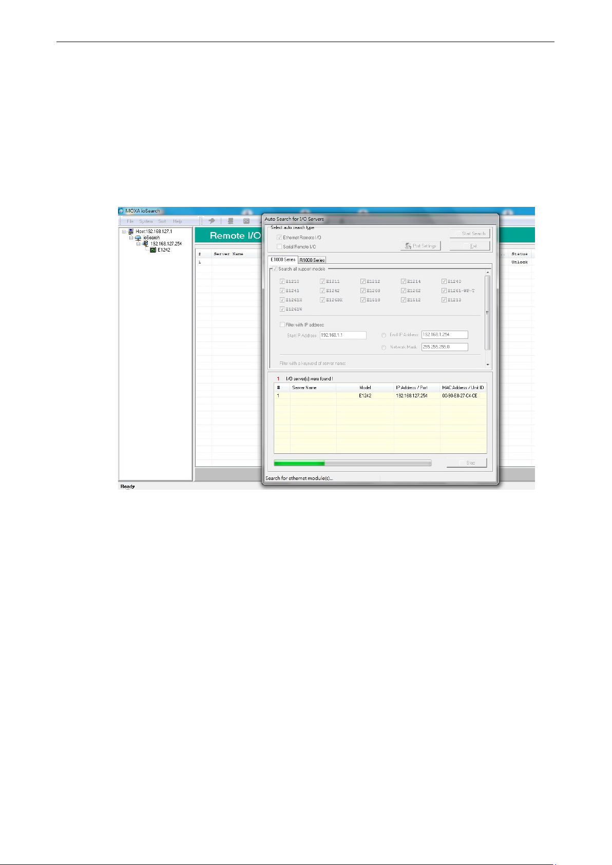
1. Installing the ioSearch™: Download the ioSearch™ utility from Moxa’s website, double click the
installation file, and then follow the installation wizard’s instructions to complete the installation.
2. Open ioSearch: After installation is finished, run ioSearch™ from Start Program Files MOXA IO
Server Utility ioSearch.
3. Search the network for the server: On the menu bar, select System Auto Scan Active Ethernet
I/O Server. A dialog window will pop up. Click Start Search to begin searching for the ioLogik E1200.
If multiple ioLogik E1200 units are installed on the same network, remember that each unit has the same
default IP address. You will need to assign a different IP address to each unit to avoid IP conflicts.
Load Factory Default Settings
There are three ways to restore the ioLogik E1200 to factory default settings.
1. Hold down the RESET button for 5 seconds
2. Right-click on the specific ioLogik device in the ioSearch™ utility and select Reset to Default
3. Select Load Factory Default from the web console
Page 27

3
3. Using the Web Console
The ioLogik E1200’s main configuration and management utility is the built-in web console, which can be used
to configure a wide range of options.
The following topics are covered in this chapter:
Introduction to the Web Console
Overview
Network Settings for the Web Console
General Settings
Ethernet Configuration
User-Defined Modbus Addressing
Default Modbus Address
AOPC Server Settings
Tag Generation
I/O Settings
DI Channels
DO Channels
AI Channels
AI Input Range
AO Channels
RTD Channels
TC Channels
Peer-to-Peer Networking
Peer-to-Peer Settings (1-50)
Sample Peer-to-Peer Configuration
DO Safe Mode Settings
AO Safe Mode Settings
SNMP
SNMP Trap
Using SNMP
Accessibility IP List
RESTful API Setting
EtherNet/IP Setting
System Management
Network Connection
Firmware Update
Import System Configuration Settings
Export System Settings
Change Password
Load Factory Defaults
Page 28
ioLogik E1200 Series Using the Web Console
3-2
NOTE
The web console is best viewed with Internet Explorer 9 or higher
supported
when using
Save/Restart
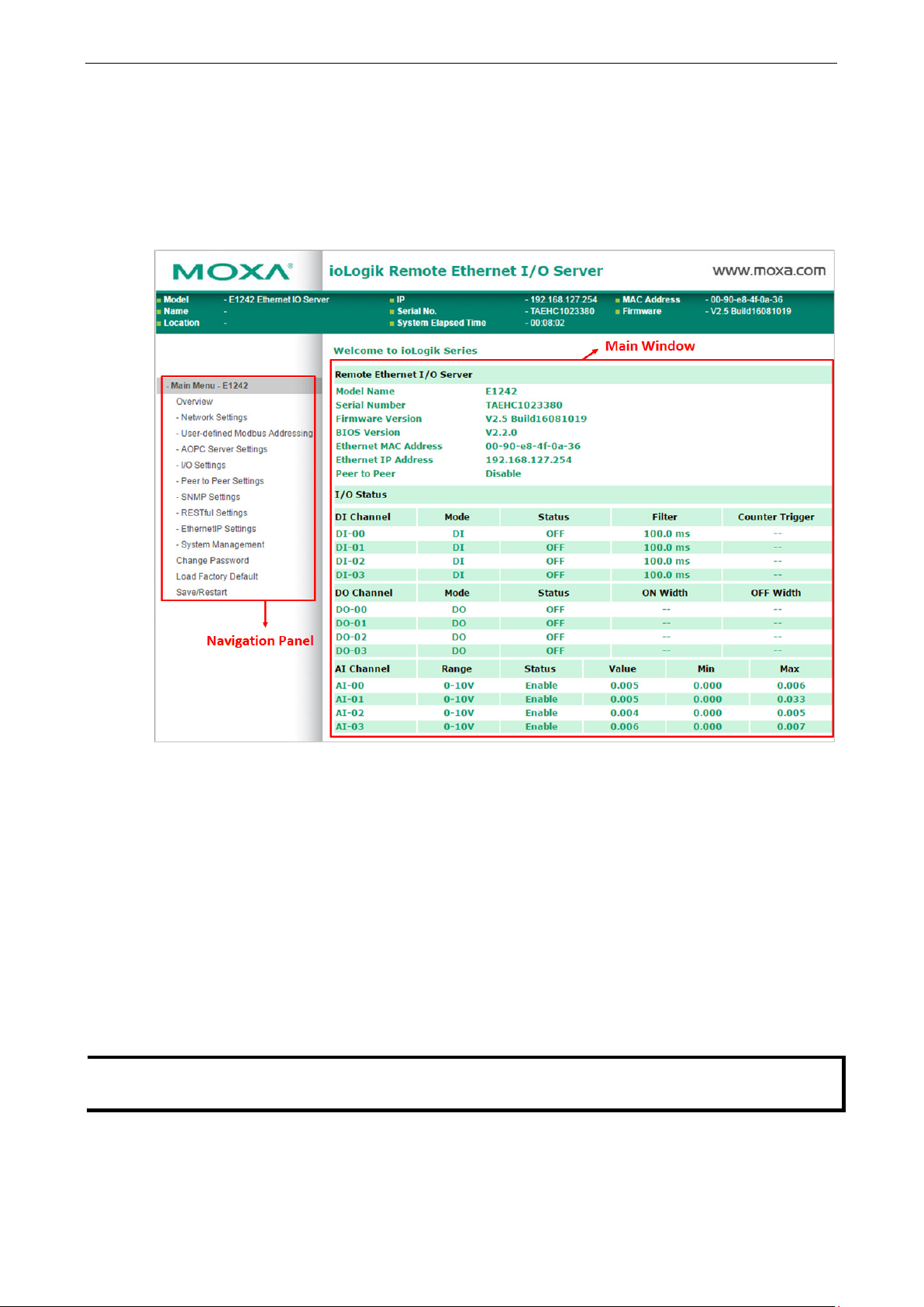
Introduction to the Web Console
The ioLogik E1200 web console is a browser-based configuration utility. When the ioLogik E1200 is connected
to your network, you may enter the server’s IP address in your web browser to access the web console.
The left panel is the navigation panel and contains an expandable menu tree for navigating among the various
settings and categories. When you click on a menu item in the navigation panel, the main window will display
the corresponding options for that item. Configuration changes can then be made in the main window. For
example, if you click on Network Settings in the navigation panel, the main window will show a page of basic
settings that you can configure.
You must click on the Submit button after making configuration changes. The Submit button will be located
at the bottom of every page that has configurable settings. If you navigate to another page without clicking the
Submit button, your changes will not be retained.
Submitted changes will not take effect until they are saved and the ioLogik E1200 is restarted! You
may save and restart the server in one step by clicking on the Save/Restart button after you submit a change.
If you need to make several changes before restarting, you may save your changes without restarting by
selecting Save/Restart in the navigation panel. If you restart the ioLogik E1200 without saving your
configuration, the ioLogik E1200 will discard all submitted changes.
other browsers.
; some functionality may not be
Page 29

ioLogik E1200 Series Using the Web Console
3-3
Overview
The Overview page contains basic information about the ioLogik E1200, including the model name, serial
number, firmware version, MAC address, and current IP address. Most importantly, you can see the current I/O
status by pressing the F5 key on the computer keyboard to refresh the page.
Page 30
ioLogik E1200 Series Using the Web Console
3-4
Network Settings for the Web Console
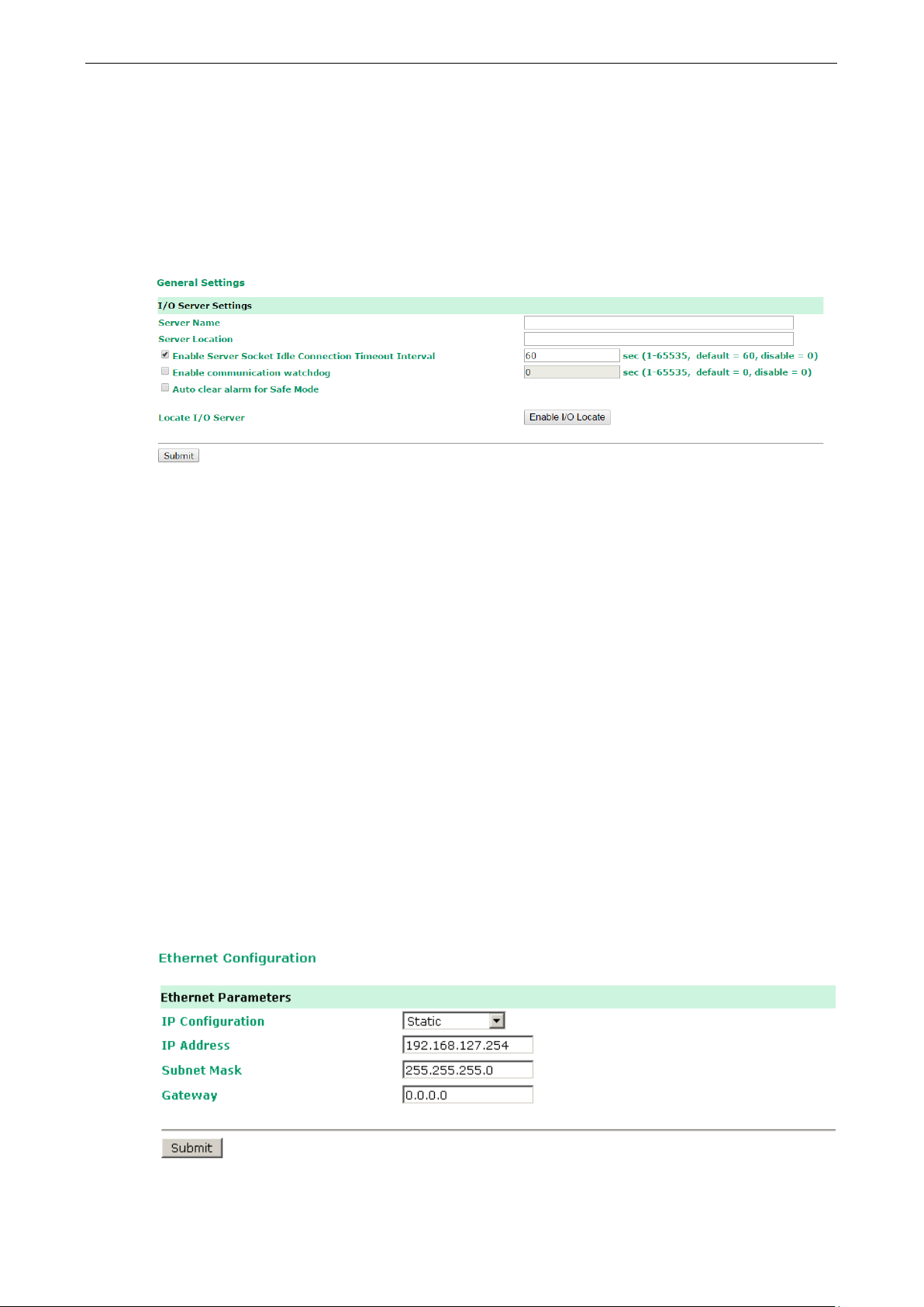
General Settings
On the General Settings page, you can assign a server name and location to assist you in differentiating
between different ioLogik E1200 units. You may also configure the Modbus/TCP timeout interval or enable the
Communication Watchdog function.
Enable Server Socket Idle Connection Timeout Interval automatically disconnects the Modbus/TCP
connection from the server after a specified time period to free up the port for the next connection.
Enable Communication Watchdog activates Safe Mode when a specified period of time has passed and
there is a loss of Modbus/TCP network connectivity. Safe Mode is specially designed for products with output
channels to output a suitable value (see Chapter 3: AO Safe Mode Setting) or status (see Chapter 3: DO
Safe Mode Setting) when the ioLogik E1200 cannot be controlled by a remote PC (such as in the event of a
network failure). By default, the watchdog is disabled. Users can configure how each output channel responds
on the I/O Settings page.
To enable the Communication Watchdog function, select the Enable Communication Watchdog checkbox,
set the timeout value, and then restart the server. When the watchdog is enabled, the ioLogik E1200 will enter
Safe Mode after there is a disruption in communication that exceeds the specified time limit.
Auto clear alarm for Safe Mode automatically clears Safe Mode when the Modbus/TCP network
connectivity returns to normal. This function is only available in models with analog or digital output channels.
Enable I/O Locate enables remote toggling of the Ready LED from off to flashing to enable remote control
of LEDs for easier location of devices when troubleshooting.
Ethernet Configuration
On the Ethernet Configuration page, you can set up a static or dynamic IP address for the ioLogik E1200, and
configure the subnet mask and gateway address.
Page 31

ioLogik E1200 Series Using the Web Console
3-5
NOTE
The maximum number of Modbus TCP master connection
ATTENTION
Disable the user
Server
to control or monitor the ioLogik E1200’s I/O status.
User-Defined Modbus Addressing
The input and output addresses can be configured on this page. Select the Enable Modbus/TCP Slave
Protocol checkbox, and then configure the start address of each Modbus function. If you do not want to use
the Modbus function, deselect the Enable Modbus/TCP Slave Protocol checkbox.
Default Modbus Address
You can view the default Modbus address for all I/O devices on the Default Modbus Address settings page.
However, only the starting address will be displayed for each item with multiple reference addresses. For
example, if the reference addresses for DI Value start from 10001 and the second DI channel’s reference
address is 10002, only the first DI channel’s Modbus address of 10001 will be displayed. See the diagram
below.
s is 10.
-defined Modbus addressing function if using the MXIO (.NET) library or MX-AOPC UA
Page 32

ioLogik E1200 Series Using the Web Console
3-6
OPC Unified Architecture
1.01
NOTE
The
MX
, and to ensure that the ioLogik is connected and alive. If the heartbeat interval is set and
the network between the ioLogik E1200 and
will detect the
stopped heartbeat and the
connectivity.
AOPC Server Settings
Moxa’s MX-AOPC Server™ is a software package operated as an OPC driver of an HMI or SCADA system. It
seamlessly connects Moxa’s ioLogik products to a wide variety of SCADA systems, including the most popular:
Wonderware, Citect, and iFix. MX-AOPC UA Server™ conforms to the OPC UA standard to connect with other
standards-compliant devices and host OPC machines.
Hardware Requirements
CPU Intel Pentium 4 or above
RAM 512 MB (1024 MB recommended)
Communication Interface Ethernet or serial
Software Requirements
Operating System Microsoft Windows 7/8/10, Microsoft Windows Server 2003/2008/2012
Editor (optional) Microsoft Office 2003 (Access or Excel) or later
Database (optional) Oracle database, Microsoft SQL Server
OPC UA Server Specifications
OPC Data Access 1.0a, 2.0, 2.05a, 3.0
Device Protocols Moxa AOPC, Modbus/TCP (master), Modbus/RTU (master)
OPC UA Logger Specifications
OPC Unified Architecture 1.01
MX-AOPC UA Server can be downloaded from Moxa’s website support page at www.moxa.com/support/.
After downloading the MX-AOPC UA Server file, unzip the file and run Install.exe. The installation program will
guide you through the installation process and install the MX-AOPC UA Server Utility.
For more details on MX-AOPC UA Server installation and use, please check the user’s manual, which can be
downloaded from Moxa’s website.
Tag Generation
Use the web console to create AOPC tags for the ioLogik E1200 by opening your browser and navigating to the
AOPC Server Settings page.
Follow these steps to create the tags and send them from the ioLogik E1200 to MX-AOPC UA Server:
1. On the AOPC & I/O Settings page, select the Enable Active OPC checkbox and specify the IP address
where the MX-AOPC UA Server is installed.
2. Select the I/O channels that need to be created in MX-AOPC UA Server.
3. Configure the Heartbeat Interval, if necessary.
Heartbeat Interval can be used to determine the connection status between the ioLogik E1200 and
-AOPC UA Server
MX-AOPC UA Server is down, MX-AOPC UA Server
Quality column in the MX-AOPC UA will display BAD to indicate the loss of
Page 33

ioLogik E1200 Series Using the Web Console
3-7
4. Click the Submit button and then the Save/Restart button on the next page.
5. On the Create AOPC Tag page, click on the Create Tags button to “push” tag configurations to the
MX-AOPC UA Server utility.
6. Launch the MX-AOPC UA Server utility and the tags will be automatically created. Remember to save the
configuration of the MX-AOPC UA Server when exiting the program.
Page 34

ioLogik E1200 Series Using the Web Console
3-8
NOTE
Confirm that the Counter Filter is not set to 0; otherwise, the counter will never be activated.
I/O Settings
DI Channels
The status of each DI (digital input) channel appears on the DI Channel Settings page.
You can also configure each channel’s digital input mode and parameters by clicking on the channel. DI
channels can operate in DI mode or Event Counter mode.
Activate Event Counter mode by selecting the Counter Start field and configure the Counter Trigger by
selecting Lo to Hi, Hi to Lo, or Both from the dropdown menu. When the Counter Start field is not selected,
you can still activate the counter by using Modbus commands.
Page 35

ioLogik E1200 Series Using the Web Console
3-9
Power On Setting: You may configure DI channels in Event Counter mode whether or not counting begins
when powering up.
Save Counter On Power Failure: The ioLogik E1200 will automatically save the counter value when there is
a power failure if this function selected.
Reset Counter: Select this function to reset the counter.
Counter Overflow: If the value of the counter is over the maximum counter value of 4294967295, the word
Overflow will be displayed in the web console; the actual counter value will restart counting from 0. To display
the current counter value in the web console, check the Clear Overflow checkbox, as shown below.
Counter Scaling: Select the Enable Counter Scaling checkbox to enable the counter scaling function. To use
this function, define the gain and offset values, and define the update interval.
For example, if the gain is 5 and the offset is 10, the counter result will be (count difference x 5) + 10.
Page 36

ioLogik E1200 Series Using the Web Console
3-10
The DI channel’s Alias Name and logic definition can also be configured on this page. You can apply the alias
name to all channels by selecting the Apply to all DI channels checkbox.
DI Channel Specification:
DO Channels
On the I/O Setting: DO (Digital Output) Channels page; you can configure each DO channel by clicking on
the channel.
Page 37

ioLogik E1200 Series Using the Web Console
3-11
NOTE
Safe Status is controlled by the Co
s, which is disabled by default.
If the
Watchdog is disabled, the ioLogik E1200 will never enter Safe Mode and your Safe Status
settings
DO channels can operate in DO mode when the status is either ON or OFF.
If you select Pulse Output mode, you can specify the ON Width and OFF Width to generate a square wave.
Pulse Width unit = 1 ms, range = 1–65535
When configuring individual channels, if the Power On Setting is selected, the Pulse Output will start as soon
as the ioLogik E1200 is powered on. If the Safe Status Setting is selected, the Pulse Output will start only
when the E1200 has entered Safe Status mode. In contrast, when neither of these settings is selected and the
Pulse Start field is selected, the ioLogik E1200 will automatically stop the Pulse Output when the ioLogik
E1200 is either powered on or in Safe Status mode.
Communication
will have no effect.
mmunication Watchdog under General Setting
Page 38

ioLogik E1200 Series Using the Web Console
3-12
The DO channel’s Alias Name and logic definition can also be configured on this page. You can apply the alias
name to all channels by clicking on the Apply to all DO channels box.
AI Channels
The current status of each AI (analog input) channel can be viewed on the AI Channel Settings page.
Click on a specific AI channel to enable or disable it by selecting the Enable AI Channel field. There are two
modes available for the AI channels:
1. Voltage Mode (See the Jumper Settings (DIO and AI) in Chapter 2 for more details)
2. Current Mode (See the Jumper Settings (DIO and AI) in Chapter 2 for more details)
Page 39

ioLogik E1200 Series Using the Web Console
3-13
NOTE
Only i
Auto Scaling and Slope-intercept functions of the AI value can be defined on this page.
AI Input Range
Set the AI input ranges for each mode, as follows:
1. Voltage Mode (V) (See Jumper Settings (DIO and AI) in Chapter 2 for more details)
There is only one default analog Voltage input range: [0-10V]
2. Current Mode (mA) (See Jumper Settings (DIO and AI) in Chapter 2 for more details)
There are three modes in the analog Current input range: [4-20 mA], [0-20 mA], [4-20 mA (Burn Out)]
nput ranges [0-10 V] and [4-20 mA] support peer-to-peer networking.
AI Input: Current Mode
Burn Out mode indicates when the Current AI has burned out. For example, the 4–20 mA Burn Out mode is
defined in the following diagram:
Page 40

ioLogik E1200 Series Using the Web Console
3-14
ATTENTION
When configuring the jumpers to select voltage or current measurement for the AI channels, open the cover by
first removing the screw on the back panel. For details on jumper settings, see the
and AI)
NOTE
The scaled value’s
Users can define Burn Out (BO) values (default = 2 mA) for selected ranges. When input values are in the
Burn Out range, raw data will register as 0000h to indicate that the analog input has burned out. The definition
of raw data is as follows:
Burnout Value (BO) 0.0 < BO < 4.0 User defined (default 2 mA)
Burnout State 0 ≤ AI < BO mA S/W output 0000h
Under Range BO ≤ AI < 4 mA S/W output raw data
Normal Range 4 ≤AI ≤ 20.00 mA S/W output raw data until FFFEh
Over Range XX > 20.00 mA S/W output FFFFh
section in Chapter 2.
Selecting Enable Point-Slope formula on the Auto Scaling Settings page will linearly convert the actual
current or voltage value into other user-defined units, such as percentage or ppm (parts per million).
Modbus address differs from the original value.
Jumper Settings (DIO
Page 41

ioLogik E1200 Series Using the Web Console
3-15
NOTE
The scaled value’s
The slope-intercept function is used to compensate when the measurement requires a slight adjustment.
The AI channel’s Alias Name can also be configured on this page.
AO Channels
The current status of each AO (analog output) channel can be viewed on the AO Channel Settings page:
Click on a specific channel to access the AO channel settings, and then select the Enable AO Channel box. The
Auto Scaling function of the AO value can be defined on the same page.
There are two modes for the AO channels, Voltage Mode (V) and Current Mode (mA).
Enabling the Point-Slope Formula function on the Auto Scaling Settings page will linearly convert the
actual current or voltage value into other user-defined units, such as percentage or ppm (parts per million).
Modbus address differs from the original value.
Page 42

ioLogik E1200 Series Using the Web Console
3-16
The AO channel’s Alias Name can also be configured on this page.
RTD Channels
The current status of each RTD (Resistance Temperature Detector) channel can be viewed on the RTD
Channel page.
Click on a specific channel to access the RTD channel settings.
Select the Enable RTD Channel checkbox and then select the sensor type from the dropdown menu that
meets the physical attachment to the ioLogik E1200.
Page 43

ioLogik E1200 Series Using the Web Console
3-17
The ioLogik E1200 allows you to calibrate the temperature sensors. In each channel configuration section,
follow the instructions and click the Calibrate button to start the RTD sensor calibration. Each calibration
requires around 30 seconds per channel.
The ioLogik E1200 allows you to manually adjust the current temperature reading. In each channel
configuration section, select the channel, apply the offset value, and click the Submit button.
TC Channels
The current status of each TC (Thermocouple) channel can be viewed on the TC Channel page.
Page 44

ioLogik E1200 Series Using the Web Console
3-18
Click on a specific channel to enable or disable the TC channel. Select the Enable TC Channel checkbox and
then select the sensor type that meets the physical attachment to the ioLogik E1200.
The ioLogik E1200 allows you to calibrate the temperature sensors. In each channel configuration section,
follow the instructions and click the Calibrate button to start the TC sensor calibration. Each calibration
requires about 30 seconds per channel.
The ioLogik E1200 allows you to manually adjust the current temperature reading. In each channel
configuration section, select the channel, apply the offset value, and click the Submit button.
Page 45

ioLogik E1200 Series Using the Web Console
3-19
NOTE
If you select a DI or AI channel in the Local Channel field, the Remote Channel field will be disabled. You need
to configure the DO
Peer-to-Peer Networking
In some remote automation implementations, the control room and field sensors may be spread far apart from
each other, often with only a single remote I/O module to collect data from all the sensors. Peer-to-peer
communication has little or no limitation as it replaces cable by integrating multiple I/O signals over a single
network cable to transmit input-to-output controls without the aid of PLCs or controllers. Featuring
peer-to-peer communications and support for channel-to-channel mapping, the ioLogik E1200 allows
simultaneous multiple target transmissions. In addition, the ioLogik E1200 supports up to 16 channels for
transmission over Ethernet (based on an emitter and receiver I/O pair).
Peer-to-Peer Settings (1-50)
The ioLogik E1200 supports up to 50 peer-to-peer mapping rules. You can configure 10 channel settings at a
time. To enable the rules, either select the Enable All box to enable all 10 channels, or select the Enable box
individually for each rule. The Local Channel dropdown menu allows you to specify the channel of the ioLogik
E1200 to configure. Type the IP address and port number of a remote ioLogik E1200 in the Remote IP and
Remote Port fields, respectively. The Remote Channel field is for you to select input channels of the remote
ioLogik E1200 when you select output channels in the Local Channel field. Set the Interval Time and On
change percentage on the local ioLogik E1200 that will trigger the transmission of a mapping signal to the
remote ioLogik E1200. The default local listen port number is 9020; this value can be set from 1 to 65535.
or AO channel on the remote ioLogik E1200.
Page 46

ioLogik E1200 Series Using the Web Console
3-20
Heartbeat
The Heartbeat function can monitor packets being transmitted between a peer-to-peer client and peer-to-peer
server. When the peer-to-peer server does not receive a packet from the peer-to-peer client within a
predefined time interval, the peer-to-peer server will enter safe mode. The default value of heart beat interval
s 60 seconds; this value can be set to between 0 and 65535 (0 means the heartbeat function is disabled).
Sample Peer-to-Peer Configuration
The following is an example of configuring DO (Server IP: 192.168.127.253) to DI (Client IP: 192.168.127.252)
peer-to-peer functionality with two ioLogik E1200 devices.
Server Settings:
Client Settings:
For client settings, the Interval Time setting and On Change percentage setting can be configured.
The following table shows the relationship between the number of rules and the maximum frequency with
which On Change percentage data can be transmitted.
Number of Rules DI max. On Change frequency
1 20 Hz
2 to 20 4 Hz
21 to 40 2 Hz
41 to 50 1 Hz
Page 47

ioLogik E1200 Series Using the Web Console
3-21
DO Safe Mode Settings
When a peer-to-peer rule on a local DO channel is not valid, or the peer-to-peer connection is down (e.g., the
Ethernet wire is unplugged or the device restarts), the local DO channel will enter Safe Mode. You can select
Hold Last, ON, or OFF from the Safe Mode Status dropdown menu for each DO channel. Once the DO
channel enters safe mode, the Safe Status will turn to ON. Click the Clear_Safe_Status button to change the
Safe Status back to NORMAL. Otherwise, it will remain in the ON position.
AO Safe Mode Settings
When a peer-to-peer rule on a local AO channel is not valid, or the peer-to-peer connection is down (e.g., the
Ethernet wire is unplugged or the device restarts), the local AO channel will enter Safe Mode. You can either set
the AO channel’s Safe Mode Value from 0–4095, or enable Hold Last Status during Safe Mode by selecting the
checkbox as shown in the following figure. Once the AO channel enters safe mode, the Safe Status will turn to
ON. Click the Clear_Safe_Status button to change the Safe Status back to NORMAL. Otherwise, it will
remain in the ON position.
SNMP
The ioLogik E1200 series remote I/O supports SNMPv1 and SNMPv2c for monitoring network I/O devices with
SNMP network management software, which is useful for building automation and telecommunications
applications.
SNMP Trap
The ioLogik E1200 series remote I/O provides standard SNMP traps and private SNMP traps for I/O devices.
Page 48

ioLogik E1200 Series Using the Web Console
3-22
SNMP manager
NOTE
You will
Standard Trap
The ioLogik E1200 series remote I/O provides the following standard SNMP traps:
Trigger Type Description
coldStart Sends SNMP trap when the agent reinitializes.
*Restart the measurement epochs because configuration data or MIB variables
may have changed.
warmStart Sends SNMP trap when the /etc/snmpd.conf file is reread and the agent
reinitializes.
*Do NOT restart the measurement epochs because configuration data or MIB
variable values have not changed. The configuration information in the
/etc/snmpd.conf file is for agent configurations that do not affect
databases.
Private Trap
The ioLogik E1200 series remote I/O provides the following private trap triggers:
Trigger Type Description
DI-change status Sends SNMP trap when DI status changes.
DO-change status Sends SNMP trap when DI status changes.
Relay-change status Sends SNMP trap when Relay status changes.
AI-burn-out Sends SNMP trap when AI reaches preset burn-out value.
AI-trigger Sends SNMP trap when AI reaches preset value.
AO-trigger Sends SNMP trap when AO reaches preset value.
RTD-trigger Sends SNMP trap when RTD reaches preset value.
TC-trigger Sends SNMP trap when TC reaches preset value.
need to load the correct MIB file to use Moxa’s private SNMP traps.
Using SNMP
Moxa has provided the ioLogik E1200 MIB file for easier analysis of SNMP data.
SNMP Agent
You can enable SNMP under SNMP Settings SNMP Agent. SNMP is used to monitor the network and I/O
devices with SNMP network management software. Use these fields to enable SNMP and set the read and write
community names, contact, and location for SNMPv1 and SNMPv2c.
Page 49

ioLogik E1200 Series Using the Web Console
3-23
NOTE
SNMP is not supported while using the peer
SNMP Trap Settings
On the SNMP Trap Settings page, you can enable SNMP and configure SNMP traps.
SNMP Trap Server
The SNMP Trap function sends an SNMP trap to up to two IP destinations. If both IP addresses are configured,
it will send to both addresses simultaneously when an SNMP trap is triggered.
SNMP Trap
To change the trap community name, type the new name in the input box located to the right of Trap
Community Name.
Enable Channel SNMP Trap by clicking on the SNMP Trap box, and then select the channel you would like to
enable.
-to-peer function.
Specific ID
The Specific ID (trap number) can be any number between 1 and 20. (You may need to consult with your
network administrator to determine how the trap numbers are used and defined on the network.)
Digital Input / Counter Trap Settings
For a digital input, the trap is triggered by the On Change function. When there is a change in the DI channel,
the SNMP will send a trap to the SNMP Server.
Page 50

ioLogik E1200 Series Using the Web Console
3-24
NOTE
SNMP Trap does not
NOTE
SNMP Trap does not
support the counter trap function.
Digital Output/Pulse Output Trap Settings
For digital output, the trap is triggered by the On Change function. When there is a change in the DO channel,
the SNMP will send a trap to the SNMP Server.
support the Pulse Output trap function.
Analog Input Trap Settings
For Analog Input, the trap is triggered when an analog input meets the preset conditions for Trigger, Value, and
Hysteresis. Refer to the AI Channel settings in Chapter 3 to set the mode.
Example:
For illustration purposes, consider the following example where we set the AI-00 channel’s trigger value to be
greater than 5 with a Hysteresis of 1 and also smaller than 5 with a Hysteresis of 1.
When Trigger = Greater, Value = 5, and Hysteresis = 1, the SNMP trap will only be triggered if the analog signal
fluctuates from 4 to 5, as depicted in Scenario 1 below. However, if we change the settings to Value = 5 and
Hysteresis = 2, the SNMP trap will only be triggered if the analog signal fluctuates from 3 to 5.
Page 51

ioLogik E1200 Series Using the Web Console
3-25
When Trigger = less, Value = 5, and Hysteresis = 1, the SNMP trap will only be triggered if the analog signal
fluctuates from 6 to 5, as depicted in Scenario 1 below. However, if we change the settings to Value = 5 and
Hysteresis = 2, the SNMP trap will only be triggered if the analog signal fluctuates from 7 to 5.
RTD Input Trap Settings
For RTD Input, the trap is triggered when the RTD input meets the preset conditions for Trigger, Value, and
Hysteresis. Refer to RTD Channel settings to set the Mode and Range.
Example:
When Trigger = Greater, Value = 400 and Hysteresis = 200, the SNMP trap will only be triggered if the RTD
signal fluctuates from 200 to 400, as depicted in Scenario 1 below. However, if we change the settings to Value
= 400 and Hysteresis = 400, the SNMP trap will only be triggered if the RTD signal fluctuates from 0 to 400.
When Trigger = less, Value = 400, and Hysteresis = 200, the SNMP trap will only be triggered if the RTD signal
fluctuates from 600 to 400, as depicted in Scenario 1 below. However, if we change the settings to Value = 400
and Hysteresis = 400, the SNMP trap will only be triggered if the RTD signal fluctuates from 800 to 400.
Page 52

ioLogik E1200 Series Using the Web Console
3-26
TC Input Trap Settings
For TC Input, the trap is triggered when the TC input meets the preset conditions for Trigger, Value, and
Hysteresis. Refer to the TC Channel settings to set the Mode and the Range.
Example:
When Trigger = Greater, Value = 400, and Hysteresis = 200, the SNMP trap will only be triggered if the TC
signal fluctuates from 200 to 400, like in scenario 1. If we change to Value = 400 and Hysteresis = 400, the
SNMP trap will only be triggered if the TC signal fluctuates from 0 to 400.
When Trigger = less, Value = 400, and Hysteresis = 200, the SNMP trap will only be triggered if the TC signal
fluctuates from 600 to 400, like in scenario 1. If we change to Value = 400 and Hysteresis = 400, the SNMP trap
will only be triggered if the TC signal fluctuates from 800 to 400.
Page 53

ioLogik E1200 Series Using the Web Console
3-27
Any host
Disable
Accessibility IP List
You can control network access to the ioLogik E1200 from the Accessibility IP List page by enabling access
only from specific IP addresses. When the Enable the accessibility IP list checkbox is enabled, a host’s IP
address must be provided and enabled in the list in order to gain access to the ioLogik E1200.
Enable access for a range of IP addresses by specifying the IP address and netmask, as follows:
To allow access for a specific IP address
Enter the IP address in the IP Address field and 255.255.255.255 in the Netmask field.
To allow access for hosts on a specific subnet
Enter 0 as the last digit in both the IP Address field and Netmask field (e.g., 192.168.1.0 and
255.255.255.0).
To allow unrestricted access
Deselect the Enable the accessible IP list option.
Refer to the following table for additional configuration examples.
Allowed Hosts IP Address/Netmask
192.168.1.120 192.168.1.120 / 255.255.255.255
192.168.1.1 to 192.168.1.254 192.168.1.0 / 255.255.255.0
192.168.0.1 to 192.168.255.254 192.168.0.0 / 255.255.0.0
192.168.1.1 to 192.168.1.126 192.168.1.0 / 255.255.255.128
192.168.1.129 to 192.168.1.254 192.168.1.128 / 255.255.255.128
Page 54

ioLogik E1200 Series Using the Web Console
3-28
NOTE
The
NOTE
The
allowed is
RESTful API Setting
The ioLogik E1200 supports RESTful API. To enable this API, select the Enable Restful API checkbox.
EtherNet/IP Setting
The ioLogik E1200 supports the EtherNet/IP protocol. To enable the protocol, select the Enable Ethernet/IP
Protocol checkbox.
EtherNet/IP function needs to be activated before it can be used. See Chapter 5 for details.
ioLogik E1200 series only supports EtherNet/IP adapter mode. The maximum number of connections
9 for read-only, and 1 for read/write.
System Management
Network Connection
TCP connections from other hosts appear on the Network Connection page. This information can assist you with
managing your devices.
Page 55

ioLogik E1200 Series Using the Web Console
3-29
WARNING
To avoid system failure while updating the firmware, follow the instructions
Firmware Update
Load new or updated firmware onto the ioLogik from the Firmware Update page.
Import System Configuration Settings
Import a configuration into the ioLogik server from the Import System Config page. This function can be used
to duplicate settings between ioLogik servers. You will be prompted for the location of the configuration file (i.e.,
“ik1212.txt”).
Export System Settings
given in Appendix I.
On the Export System Settings page, you can export a copy of the ioLogik’s configuration file for backup or
import into another ioLogik server.
Page 56

ioLogik E1200 Series Using the Web Console
3-30
NOTE
Password can only
ATTENTION
If you forget the password, the ONLY way to configure the ioLogik E1200 is by using the Reset button to load
the factory default settings.
Before you set a password
finished setting up your ioLogik E1200. Your configuration can then be easily imported back into the ioLogik
E1200 if you need to reset the ioLogik E1200 due to a forgotte
Change Password
To make any changes to the ioLogik E1200’s password protection settings, you will first need to enter the old
password. Leave the Old password field blank if you are setting up password protection for the first time. To
set up a new password or change the existing password, enter the new password (maximum of 16 characters)
in both the New password and Retype password fields. To remove password protection, leave the New
password and Retype password fields blank.
use English, numeric, or special characters e.g. ~!@#$%
for the first time, it is a good idea to export the configuration file when you have
Load Factory Defaults
This function will reset all of the ioLogik E1200’s settings to the factory default values. All previous settings,
including the console password, will be lost.
n password or for other reasons.
Save/Restart
If you change the configuration, do not forget to reboot the system.
Page 57

4
4. Using ioSearch™
This chapter describes ioSearch™, which is used to search for and locate ioLogik E1200 units.
The following topics are covered in this chapter:
Introduction to ioSearch™
ioSearch™ Main Screen
Main Screen Overview
ioSearch™ Setup
System
Sort
Quick Links
Main Function
Locate
Firmware Upgrade
Unlock
Import
Export
Change IP Address
Batch TCP/IP Configuration on Multiple Devices
Change Server Name
Activate EtherNet/IP
Restart System
Reset to Default
Mass Deployment (Import)
Mass Deployment (Export)
Page 58

ioLogik E1200 Series Using ioSearch™
4-2
3. Quick link
5
3
Introduction to ioSearch™
Moxa’s ioSearch™ utility is software tool that searches for ioLogik E1200 units on a physical network. The
following functions are supported by the ioSearch™ utility:
• Search for and locate ioLogik E1200 units
• Configure IP addresses
• Upgrade firmware for multiple ioLogik E1200 units (same model)
• Export configuration files from multiple ioLogik E1200 units
• Import configuration files from multiple ioLogik E1200 units (same model)
• Reset to default for multiple ioLogik E1200 units
• Activate the EtherNet/IP function for multiple ioLogik E1200 units (you will need to register the device
before activating it)
ioSearch™ Main Screen
Main Screen Overview
The main screen displays the results of a broadcast search for ioLogik E1200 units.
4
ioSearch™ Main Screen
1. Title
2. Menu bar
4. Navigation panel
5. Main window
Page 59

ioLogik E1200 Series Using ioSearch™
4-3
ioSearch™ Setup
System
Several operations are possible from the System menu.
Auto Scan Active Ethernet I/O Servers will search for ioLogik servers on the network. When connecting for
the first time or recovering from a network disconnection, you can use this command to find I/O servers that
are on the network.
Network Interface allows you to select a network to use, if the PC has multiple network adapters installed.
Page 60

ioLogik E1200 Series Using ioSearch™
4-4
4
Locate an ioLogik E1200
Sort
The Sort menu allows the server list in the navigation panel to be sorted by ioLogik connection and server
(model).
Quick Links
Quick links are provided to search for I/O servers on the network and sort the server list.
1 Automatically search the local network
2 Sort by ioLogik E1200’s IP address (connection)
3 Sort by ioLogik E1200 model
5 Upgrade Firmware
6 Import settings
7 Export settings
8 Unlock an ioLogik E1200 which is password protected
9 Change IP Address of an ioLogik E1200
Main Function
Right click on a particular ioLogik E1200 to view the ioSearch™ function menu.
Page 61

ioLogik E1200 Series Using ioSearch™
4-5
NOTE
If your product is using f
firmware version
ATTENTION
Do not interrupt the firmware update process! An interruption in the process may result in your device
becoming unrecoverable.
Locate
The locate function helps users find a dedicated ioLogik on the network. When this function is triggered, the
ready LED on the selected unit will start to blink indicating its location.
Firmware Upgrade
The ioLogik E1200 supports a remote firmware upgrade function. Enter the path to the firmware file or click on
the icon to browse for the file. The wizard will lead you through the process until the server is restarted.
.
irmware version V3.0 or higher, use ioSearch V2.0 or higher to upgrade to a newer
Batch Upgrades on Multiple Devices of the Same Model
Batch firmware upgrades are possible on multiple devices of the same ioLogik model. To upgrade multiple
models, press the “Shift” key, select “ioLogik”, and right click to process multiple firmware upgrades.
Page 62

ioLogik E1200 Series Using ioSearch™
4-6
Unlock
If an ioLogik E1200 is password protected, unlock the ioLogik E1200 by entering the password before using any
of the functions.
Import
Select this command to reload a configuration that was exported to a text file.
Importing one configuration file to multiple ioLogik E1200 units (same model) is allowed. To do this, press the
“Shift” key, select “ioLogik”, and then right click.
Export
The export function is used to export the current configuration file of an ioLogik E1200. The export file format
will be ik12xx.txt where “xx” represents the model type of the ioLogik E1200.
Exporting multiple files for different models of ioLogik E1200 is allowed. The file format is ik12xx_MAC
Address.txt, where the xx represents the model types of the ioLogik E1200.
e.g., ik1214_00-90-E8-66-32-19.txt
To export multiple configuration files, select the ioLogik and right click to process this function.
Page 63

ioLogik E1200 Series Using ioSearch™
4-7
Change IP Address
The Change IP Address function allows you to directly modify the IP address for one or multiple ioLogik E1200
series devices, and is especially useful for first time installation.
First, select the ioLogik E1200 device(s) you wish to modify. Then, right-click on the device(s) and select
Change IP Address from the dropdown menu to open the Change IP Address window. After changing the IP
address, click Set to complete setup, and search the network again to reveal the modified IP addresses.
Batch TCP/IP Configuration on Multiple Devices
Users can batch modify IP addresses, subnet masks, and gateways for devices of the same model from a single
window while submitting the changes at one time. First, select several devices of the same model, click the
right mouse button, and then click Change IP Address in the pop-up menu to launch a new window.
The following screenshot shows the window used to modify IP addresses, subnet masks, and gateways. Users
can modify each item and click Set to confirm the modification, or click the Advance button to automatically
assign IP addresses incrementally.
Page 64

ioLogik E1200 Series Using ioSearch™
4-8
NOTE
The EtherNet/IP function n
After clicking the Advance button, a window will pop up to allow users to use ioSearch™ to set the IP address
by MAC address. ioSearch™ will automatically set sequential IP addresses on the selected devices, with the
subnet mask and gateway set to the same value.
Change Server Name
To change the server name, click on the Change Server Name option, type the name in the Server Name
box, and then click Advance.
Activate EtherNet/IP
Right click on the device and select Activate EtherNet/IP. The progress of the activation process will be
shown onscreen, and ioSearch will inform you when the activation has finished.
eeds to be activated before it can be used. See Chapter 5 for details.
Page 65

ioLogik E1200 Series Using ioSearch™
4-9
Restart System
Select this command to restart the selected ioLogik E1200.
Restarting multiple ioLogik E1200 units is allowed. Select the ioLogik E1200 and right click to process this
function.
Reset to Default
Select this function to reset all settings, including console password, to factory default values.
Resetting multiple ioLogik E1200 units to the default configuration is allowed. Select the ioLogik E1200 and
right click to process this function.
Mass Deployment (Import)
Users can import E1200 series module information via ioSearch™. Select this command to reload a
configuration from an exported .CSV file.
Page 66

ioLogik E1200 Series Using ioSearch™
4-10
Mass Deployment (Export)
Users can export E1200 series module information via ioSearch™. The export file format will be
E1200_Series_List.
Page 67

5
5. Activating the EtherNet/IP Function
The ioLogik E1200 series will support the EtherNet/IP protocol after it has been registered and activated. In this
chapter, we explain how to activate the EtherNet/IP function in the ioLogik E1200 series. The EtherNet/IP
function can only be activated for firmware and utility versions that are the same as or more recent than those
listed below.
Firmware:
• ioLogik E1210 V2.5 (std. version)
• ioLogik E1211 V2.4 (std. version)
• ioLogik E1212 V2.5 (std. version)
• ioLogik E1213 V2.6 (std. version)
• ioLogik E1214 V2.5 (std. version)
• ioLogik E1240 V2.4 (std. version)
• ioLogik E1241 V2.5 (std. version)
• ioLogik E1242 V2.5 (std. version)
• ioLogik E1260 V2.5 (std. version)
• ioLogik E1262 V2.5 (std. version)
Utility:
• ioSearch V1.15 (std. version)
Page 68

ioLogik E1200 Series Activating the EtherNet/IP Function
5-2
Take the following steps to register a license and activate multiple devices:
Step 1: Assign the license file folder
To assign a folder in which to place the license file, click System Options and then click the settings icon to
open the following window. Type in the path of the license folder, and then click OK.
Step 2: Get the device’s serial number
Locate the serial number on the ioLogik E1200 device. The device serial number can be found on the device
label, as shown in the picture below.
Page 69

ioLogik E1200 Series Activating the EtherNet/IP Function
5-3
Step 3: Log in to Moxa’s license server
Go to Moxa’s Software Licensing website (http://license.moxa.com
password, or apply for an account if this is your first visit to the site.
) and log in with your Moxa account and
Step 4: Register the device on the Moxa Licensing Server
On the Software Licensing website, navigate to Activate Your Software Software Function ioLogik
E1200 EtherNet/IP. First register a single product by inputting the serial number. Click the Submit button
to register the product.
Page 70

ioLogik E1200 Series Activating the EtherNet/IP Function
5-4
Step 5: Download the license file and put it in the designated folder
Download the license file to the folder that was assigned in Step 1, and then unzip the license file.
Step 6: Use ioSearch to Activate the EtherNet/IP function in the ioLogik E1200 series
Connect the ioLogik E1200 devices to the computer and use ioSearch to search for the devices. Device
information will be displayed in the window. Click the EIP icon in the toolbar to activate multiple devices in the
list, or select the unlicensed devices, right click on the devices, and select Activate EtherNet/IP. The progress
of the activation process can be viewed, and ioSearch will inform you when the activation is complete.
Page 71

6
6. How to Connect the ioLogik E1200 to an
Allen-Bradley PLC
In this chapter, we provide a step-by-step example of how to connect the ioLogik E1200 series device with an
Allen-Bradley PLC by the EtherNet/IP protocol. In this example, the Allen-Bradley PLC is the EtherNet/IP
Scanner and the ioLogik E1200 is the adapter. The system architecture is displayed below. There are two
sections in this chapter. The first section explains how to install the ioLogik E1200 series’ EDS files in the
RSLogix 5000, and the second section explains how to connect the ioLogik E1200 with the Allen-Bradley PLC.
Page 72

ioLogik E1200 Series How to Connect the ioLogik E1200 to an Allen-Bradley PLC
6-2
EDS Installation of the ioLogik E1200 Series in Rockwell Software RSLogix 5000
1. Start the RSLogix 5000 and open the EDS Hardware Installation Tool in Tools EDS Hardware
Installation Tool.
2. The wizard will start and the following window will pop out, click Next and then select Register an EDS
file(s), followed by Next.
Page 73

ioLogik E1200 Series How to Connect the ioLogik E1200 to an Allen-Bradley PLC
6-3
3. There are two ways to register the EDS files. The first is to register a single file, and the second is to register
the EDS files by a folder.
A. If you want to register one EDS file, select Register a single file and then click Browse.
B. If you want to register several EDS files, put all the EDS files in one folder, select Register a directory
of EDS files and then click Browse.
4. Select EDS files and click Open, then it will go back to the wizard. Please click Next to finish the EDS file
selection.
A. Single EDS file
Page 74

ioLogik E1200 Series How to Connect the ioLogik E1200 to an Allen-Bradley PLC
6-4
B. Select EDS file folder
5. The EDS Wizard will evaluate the EDS file you selected and display the result, then click Next. In the
following window, you can change the device image. If you do not intend to change the image, please click
Next.
A. Single EDS file
B. EDS files folder
Page 75

ioLogik E1200 Series How to Connect the ioLogik E1200 to an Allen-Bradley PLC
6-5
6. Complete the final step of the EDS Wizard by clicking Next and then Finish.
A. Single EDS file
B. EDS files folder
Page 76

ioLogik E1200 Series How to Connect the ioLogik E1200 to an Allen-Bradley PLC
6-6
Establishing communication between the ioLogik E1200 device and the Allen-Bradley PLC
1. Open the RSLogix 5000 and then open a new project by pressing File New.
Page 77

ioLogik E1200 Series How to Connect the ioLogik E1200 to an Allen-Bradley PLC
6-7
2. Select your PLC model under Type and key in the project name in the window. The
CompactLogix5324ER-QBFC1B will be used as an example.
Page 78

ioLogik E1200 Series How to Connect the ioLogik E1200 to an Allen-Bradley PLC
6-8
3. After the project creation, you can see the project information in the left window. Right click Ethernet and
then select New Module and the ioLogik E1200 module can be added into the project.
Page 79

ioLogik E1200 Series How to Connect the ioLogik E1200 to an Allen-Bradley PLC
6-9
4. In the Select Module Type window, choose the ioLogik E1200 model you want to add. You can use a key
word and select the module type to speed up the search. The ioLogik E1212 is used here as an example.
5. In the New Module window, key in the module name and module IP. The default module definition is
Exclusive Owner. If you want to change it, click change and then choose another type.
Page 80

ioLogik E1200 Series How to Connect the ioLogik E1200 to an Allen-Bradley PLC
6-10
6. RSLogix 5000 will recognize and create the ioLogik E1212 tags automatically. You can check the tag
structure in the window.
7. To download the tag structure to the Allen-Bradley PLC, please go to Communications Who Active to
select the active PLC.
8. Select the PLC in Who Active and then click the Go Online, followed by Download. The RSLogix 5000 will
display a pop-up message to inform you the download is complete.
Page 81

ioLogik E1200 Series How to Connect the ioLogik E1200 to an Allen-Bradley PLC
6-11
9. Change the ioLogik_E1212.O.Data[0].4 status from 0 to 1 in RSLogix 5000 and the DO-04 status will
change from OFF to ON. The ioLogik E1200 will now be successfully connected to the Allen-Bradley PLC.
Page 82

7
7. RESTful API Implementation
The latest firmware versions of ioLogik E1200 series products support a RESTful API protocol. In this chapter,
we show how to implement a RESTful API for applications. A RESTful API function can only be activated for
firmware and utility versions that are the same as or more recent than those listed below.
Firmware:
• ioLogik E1210 V2.5 (std. version)
• ioLogik E1211 V2.4 (std. version)
• ioLogik E1212 V2.5 (std. version)
• ioLogik E1213 V2.6 (std. version)
• ioLogik E1214 V2.5 (std. version)
• ioLogik E1240 V2.4 (std. version)
• ioLogik E1241 V2.5 (std. version)
• ioLogik E1242 V2.5 (std. version)
• ioLogik E1260 V2.5 (std. version)
• ioLogik E1262 V2.5 (std. version)
Utility:
• ioSearch V1.15 (std. version)
Page 83

ioLogik E1200 Series RESTful API Implementation
7-2
Introduction
Since RESTful APIs are based on HTTP, they are highly compatible with a variety of programming languages
(including C# and JavaScript). Consequently, you do not need to learn a new programming language to
communicate with Moxa’s ioLogik E1200 products. The RESTful API’s GET method makes it easy for IT
professionals to get data, and the PUT method allows you to easily change the configuration and/or status of
your devices.
Configuring RESTful API Settings
Before implementation, three points need to be checked:
1. The RESTful API is active
To enable the RESTful API, enter the server’s IP address in your web browser to access the web console.
Under RESTful Settings, select the Enable Restful API checkbox. Click Submit to enable it. It will be
activated after saving and restarting the configuration.
2. Header information
The operating parameters of http should be specified in the header:
• Accept: vdn.dac.v1
• Content-Type: application/json
3. Supported Methods
Moxa’s ioLogik E1200 products support GET, PUT, and OPTIONS methods.
After the settings are ready to go, follow the sample step-by-step instructions on how to use a web service
to GET and PUT data.
Using RESTful API via a Web Service
This example uses the Windows 7 OS, with the server configured as follows:
• Note.js: v5.3.0
• Express: v4.15.0
Page 84

ioLogik E1200 Series RESTful API Implementation
7-3
The following flowcharts illustrate how only four steps are needed to implement the GET and PUT methods.
GET: 4 steps (status updated at regular intervals)
PUT: 4 steps (triggered by command)
1. GET request: The server sends RESTful API GET requests to the ioLogik E1200 to get information.
Page 85

ioLogik E1200 Series RESTful API Implementation
7-4
NOTE
When sending requests, headers should be included to ensure that the RESTful API is implemented
successfully. Headers should include the following information:
•
•
PUT request: The server sends RESTful API PUT requests to the ioLogik E1200 to change information.
Accept: vdn.dac.v1
Content-Type: application/json
2. Send JSON file: The ioLogik E1200 sends a response to the server in JSON format.
3. Parse JSON file: The content is parsed and saved by the server.
Page 86

ioLogik E1200 Series RESTful API Implementation
7-5
4. Show value: The information can be displayed in various interfaces. Here, we take a web browser as an
example:
GET: Show current I/O status
PUT: The counter status will be changed from START to STOP.
Troubleshooting Reference
The ioLogik E1200 series supports various combinations of I/O points. To get detailed data structure
information for troubleshooting purposes, use the ioSearch utility’s built-in help tool.
Path: Help ioSearch Help RESTful API ioLogik E1200 RESTful API
In this help file, users can find information such as data type, data structure, supported methods, and response
codes.
Page 87

A
A. Modbus/TCP Default Address Mappings
The following topics are covered in this appendix:
Supported Function Code
ioLogik E1210 Modbus Address and Register Map
ioLogik E1211 Modbus Address and Register Map
ioLogik E1212 Modbus Address and Register Map
ioLogik E1213 Modbus Address and Register Map
ioLogik E1214 Modbus Address and Register Map
ioLogik E1240 Modbus Address and Register Map
ioLogik E1241 Modbus Address and Register Map
ioLogik E1242 Modbus Address and Register Map
ioLogik E1260 Modbus Address and Register Map
ioLogik E1262 Modbus Address and Register Map
Page 88

ioLogik E1200 Series Modbus/TCP Default Address Mappings
A-2
NOTE
The Modbus/TCP ID of the ioLogik E1200 is set to “1” by default.
Supported Function Code
Point Type Register
(Decimal)
01: COIL STATUS 0xxxx R/W bit 1, 5, 15
02: INPUT STATUS 1xxxx R bit 2
03: HOLDING REGISTER 4xxxx R/W word 3, 6, 16
04: INPUT REGISTER 3xxxx R word 4
Access Type Supported Function Code
ioLogik E1210 Modbus Address and Register Map
I/O
Parameter Name Description Start
Address
(decimal)
DI_counterOverflowFl
ag
DI_counterOverflowFl
agClear
DI_counterReset 1: reset to
DI_counterStatus 0: STOP, 1:
DI_counterValue high/low word 0016 04:INPUT
DI_status 0: OFF, 1: ON 0000 02:INPUT
DI-all_statusFromDI-
00
0: Normal, 1:
Overflow
1: clear
overflow flag
initial value
START
0: OFF, 1: ON 0048 04:INPUT
1000 02:INPUT
0288 01:COIL
0272 01:COIL
0256 01:COIL
Point Type Start
Register
(decimal)
11001 16 R bit
STATUS
00289 16 R/W bit
STATUS
00273 16 R/W bit
STATUS
00257 16 R/W bit
STATUS
30017 32 R 2 words
REGISTER
10001 16 R bit
STATUS
30049 1 R word
REGISTER
Length Access Type
System
Parameter Name Description Start
deviceName Each byte
represents
ASCII code of
each character
deviceUpTime unit: sec(s) 5020 04:INPUT
firmwareVersion e.g. V1.2.3 ->
1st byte: 1,
2nd byte: 2,
3rd byte: 3
Point Type Start
Address
(decimal)
5040 04:INPUT
REGISTER
REGISTER
5029 04:INPUT
REGISTER
Length Access Type
Register
(decimal)
305041 30 R word
35021 2 R word
35030 2 R word
Page 89

ioLogik E1200 Series Modbus/TCP Default Address Mappings
A-3
byte: 192, 2nd
byte: 168, 3rd
byte: 127, 4th
byte: 144, 3rd
byte: 232, 4th
STATUS
Parameter Name Description Start
Address
(decimal)
firmwareBuildDate e.g.
Build1605171
8 -->
16051718
lanIp e.g.
192.168.127.
254 -> 1st
byte: 254
lanMac e.g.
00:90:E8:3E:
18:CC -> 1st
byte: 0, 2nd
byte: 62, 5th
byte: 24, 6th
byte: 204
modelName Each byte
represents
ASCII code of
each character
5031 04:INPUT
5027 04:INPUT
5024 04:INPUT
5000 04:INPUT
Point Type Start
Register
(decimal)
35032 2 R word
REGISTER
35028 2 R word
REGISTER
35025 3 R word
REGISTER
35001 10 R word
REGISTER
Length Access Type
ioLogik E1211 Modbus Address and Register Map
I/O
Parameter Name Description Start
Address
(decimal)
DO_p2pSafeModeFla
gClear
DO_p2pSafeModeFlag 0: OFF, 1: ON 4112 02:INPUT
DO_p2pStatus 0: OFF, 1: ON 4096 02:INPUT
DO_pulseCount 0036 03:HOLDIN
DO_pulseOffWidth unit: 1 ms 0068 03:HOLDIN
DO_pulseOnWidth unit: 1 ms 0052 03:HOLDIN
DO_pulseStatus 0: STOP, 1:
1: clear safe
mode flag
START
4128 01:COIL
0016 01:COIL
Point Type Start
Register
(decimal)
04129 16 R/W bit
STATUS
14113 16 R bit
STATUS
14097 16 R bit
40037 16 R/W word
G
REGISTER
40069 16 R/W word
G
REGISTER
40053 16 R/W word
G
REGISTER
00017 16 R/W bit
STATUS
Length Access Type
Page 90

ioLogik E1200 Series Modbus/TCP Default Address Mappings
A-4
each character
byte: 192, 2nd
each character
Parameter Name Description Start
Address
(decimal)
DO_status 0: OFF, 1: ON 0000 01:COIL
DO-all_statusFromDO
-00
0: OFF, 1: ON 0032 03:HOLDIN
Point Type Start
STATUS
G
REGISTER
System
Parameter Name Description Start
Address
(decimal)
deviceName Each byte
represents
ASCII code of
deviceUpTime unit: sec(s) 5020 04:INPUT
firmwareVersion e.g. V1.2.3 ->
1st byte: 1,
2nd byte: 2,
3rd byte: 3
firmwareBuildDate e.g.
Build1605171
8 -->
16051718
lanIp e.g.
192.168.127.
254 -> 1st
5040 04:INPUT
5029 04:INPUT
5031 04:INPUT
5027 04:INPUT
Point Type Start
REGISTER
REGISTER
REGISTER
REGISTER
REGISTER
Length Access Type
Register
(decimal)
00001 16 R/W bit
40033 1 R/W word
Length Access Type
Register
(decimal)
35041 30 R word
35021 2 R word
35030 2 R word
35032 2 R word
35028 2 R word
byte: 168, 3rd
byte: 127, 4th
byte: 254
lanMac e.g.
00:90:E8:3E:
18:CC -> 1st
byte: 0, 2nd
byte: 144, 3rd
byte: 232, 4th
byte: 62, 5th
byte: 24, 6th
byte: 204
modelName Each byte
represents
ASCII code of
watchdogAlarmFlag 1: clear
watchdog
alarm
5024 04:INPUT
REGISTER
5000 04:INPUT
REGISTER
4144 01:COIL
STATUS
35025 3 R word
35001 10 R word
04145 1 R/W bit
Page 91

ioLogik E1200 Series Modbus/TCP Default Address Mappings
A-5
STATUS
REGISTER
ioLogik E1212 Modbus Address and Register Map
I/O
Parameter Name Description Start
Address
(decimal)
DI_counterOverflowFl
ag
DI_counterOverflowFl
agClear
DI_counterReset 1: reset to
DI_counterStatus 0: STOP, 1:
DI_counterValue high/low word 0016 04:INPUT
DI_status 0: OFF, 1: ON 0000 02:INPUT
DI-all_statusFromDI-
00
DO_p2pSafeModeFla
gClear
DO_p2pSafeModeFlag 0: OFF, 1: ON 4112 02:INPUT
0: Normal, 1:
Overflow
1: clear
overflow flag
initial value
START
0: OFF, 1: ON 0048 04:INPUT
1: clear safe
mode flag
1000 02:INPUT
0288 01:COIL
0272 01:COIL
0256 01:COIL
4128 01:COIL
Point Type Start
Register
(decimal)
11001 16 R bit
STATUS
00289 16 R/W bit
STATUS
00273 16 R/W bit
STATUS
00257 16 R/W bit
STATUS
30017 32 R 2 words
REGISTER
10001 16 R bit
STATUS
30049 1 R word
REGISTER
04129 8 R/W bit
STATUS
14113 8 R bit
Length Access Type
DO_p2pStatus 0: OFF, 1: ON 4096 02:INPUT
STATUS
DO_pulseCount 0036 03:HOLDIN
G
DO_pulseOffWidth unit: 1 ms 0068 03:HOLDIN
G
REGISTER
DO_pulseOnWidth unit: 1 ms 0052 03:HOLDIN
G
REGISTER
DO_pulseStatus 0: STOP, 1:
START
DO_status 0: OFF, 1: ON 0000 01:COIL
DO-all_statusFromDO
-00
0: OFF, 1: ON 0032 03:HOLDIN
0016 01:COIL
STATUS
STATUS
G
REGISTER
14097 8 R bit
40037 8 R/W word
40069 8 R/W word
40053 8 R/W word
00017 8 R/W bit
00001 8 R/W bit
40033 1 R/W word
Page 92

ioLogik E1200 Series Modbus/TCP Default Address Mappings
A-6
byte: 192, 2nd
System
Parameter Name Description Start
Address
(decimal)
deviceName Each byte
represents
ASCII code of
each character
deviceUpTime unit: sec(s) 5020 04:INPUT
firmwareVersion e.g. V1.2.3 ->
1st byte: 1,
2nd byte: 2,
3rd byte: 3
firmwareBuildDate e.g.
Build1605171
8 -->
16051718
lanIp e.g.
192.168.127.
254 -> 1st
5040 04:INPUT
5029 04:INPUT
5031 04:INPUT
5027 04:INPUT
Point
Type
REGISTER
REGISTER
REGISTER
REGISTER
REGISTER
Start
Register
(decimal)
35041 30 R word
35021 2 R word
35030 2 R word
35032 2 R word
35028 2 R word
Length Access Type
byte: 168, 3rd
byte: 127, 4th
byte: 254
lanMac e.g.
00:90:E8:3E:
18:CC -> 1st
byte: 0, 2nd
byte: 144, 3rd
byte: 232, 4th
byte: 62, 5th
byte: 24, 6th
byte: 204
modelName Each byte
represents
ASCII code of
each character
watchdogAlarmFlag 1: clear
watchdog
alarm
5024 04:INPUT
REGISTER
5000 04:INPUT
REGISTER
4144 01:COIL
STATUS
35025 3 R word
35001 10 R word
04145 1 R/W bit
Page 93

ioLogik E1200 Series Modbus/TCP Default Address Mappings
A-7
STATUS
REGISTER
ioLogik E1213 Modbus Address and Register Map
I/O
Parameter Name Description Start
Address
(decimal)
DI_counterOverflowFl
ag
DI_counterOverflowFl
agClear
DI_counterReset 1: reset to
DI_counterStatus 0: STOP, 1:
DI_counterValue high/low word 0016 04:INPUT
DI_status 0: OFF, 1: ON 0000 02:INPUT
DI-all_statusFromDI-
00
DO_p2pSafeModeFla
gClear
DO_p2pSafeModeFlag 0: OFF, 1: ON 4112 02:INPUT
0: Normal, 1:
Overflow
1: clear
overflow flag
initial value
START
0: OFF, 1: ON 0048 04:INPUT
1: clear safe
mode flag
1000 02:INPUT
0288 01:COIL
0272 01:COIL
0256 01:COIL
4128 01:COIL
Point
Type
STATUS
STATUS
STATUS
STATUS
REGISTER
STATUS
REGISTER
STATUS
Start
Register
(decimal)
11001 12 R bit
00289 12 R/W bit
00273 12 R/W bit
00257 12 R/W bit
30017 24 R 2 words
10001 12 R bit
30049 1 R word
04129 8 R/W bit
14113 8 R bit
Length Access Type
DO_p2pStatus 0: OFF, 1: ON 4096 02:INPUT
DO_pulseCount 0036 03:HOLDI
DO_pulseOffWidth unit: 1 ms 0068 03:HOLDI
DO_pulseOnWidth unit: 1 ms 0052 03:HOLDI
DO_pulseStatus 0: STOP, 1:
START
DO_status 0: OFF, 1: ON 0000 01:COIL
DO-all_statusFromDO
-00
0: OFF, 1: ON 0032 03:HOLDI
STATUS
NG
NG
REGISTER
NG
REGISTER
0016 01:COIL
STATUS
STATUS
NG
REGISTER
14097 8 R bit
40037 8 R/W word
40069 8 R/W word
40053 8 R/W word
00017 8 R/W bit
00001 8 R/W bit
40033 1 R/W word
Page 94

ioLogik E1200 Series Modbus/TCP Default Address Mappings
A-8
byte: 192, 2nd
System
Parameter Name Description Start
Address
(decimal)
deviceName Each byte
represents
ASCII code of
each character
deviceUpTime unit: sec(s) 5020 04:INPUT
firmwareVersion e.g. V1.2.3 ->
1st byte: 1,
2nd byte: 2,
3rd byte: 3
firmwareBuildDate e.g.
Build1605171
8 -->
16051718
lanIp e.g.
192.168.127.
254 -> 1st
5040 04:INPUT
5029 04:INPUT
5031 04:INPUT
5027 04:INPUT
Point
Type
REGISTER
REGISTER
REGISTER
REGISTER
REGISTER
Start
Register
(decimal)
35041 30 R word
35021 2 R word
35030 2 R word
35032 2 R word
35028 2 R word
Length Access Type
byte: 168, 3rd
byte: 127, 4th
byte: 254
lanMac e.g.
00:90:E8:3E:
18:CC -> 1st
byte: 0, 2nd
byte: 144, 3rd
byte: 232, 4th
byte: 62, 5th
byte: 24, 6th
byte: 204
modelName Each byte
represents
ASCII code of
each character
watchdogAlarmFlag 1: clear
watchdog
alarm
5024 04:INPUT
REGISTER
5000 04:INPUT
REGISTER
4144 01:COIL
STATUS
35025 3 R word
35001 10 R word
04145 1 R/W bit
Page 95

ioLogik E1200 Series Modbus/TCP Default Address Mappings
A-9
et
current count
STATUS
ioLogik E1214 Modbus Address and Register Map
I/O
Parameter Name Description Start
Address
(decimal)
DI_counterOverflowFl
ag
DI_counterOverflowFl
agClear
DI_counterReset 1: reset to
DI_counterStatus 0: STOP, 1:
DI_counterValue high/low word 0016 04:INPUT
DI_status 0: OFF, 1: ON 0000 02:INPUT
DI-all_statusFromDI-
00
RLY_currentCount high/low word 0096 04:INPUT
RLY_currentCountRes
0: Normal, 1:
Overflow
1: clear
overflow flag
initial value
START
0: OFF, 1: ON 0048 04:INPUT
1: reset
1000 02:INPUT
0288 01:COIL
0272 01:COIL
0256 01:COIL
0048 01:COIL
Point
Type
STATUS
STATUS
STATUS
STATUS
REGISTER
STATUS
REGISTER
REGISTER
Start
Register
(decimal)
11001 6 R bit
00289 6 R/W bit
00273 6 R/W bit
00257 6 R/W bit
30017 12 R 2 words
10001 6 R bit
30049 1 R word
30097 12 R 2 words
00048 6 R/W bit
Length Access Type
RLY_p2pSafeModeFla
gCelar
RLY_p2pSafeModeFlag 0: OFF, 1: ON 4112 02:INPUT
RLY_p2pStatus 0: OFF, 1: ON 4096 02:INPUT
RLY_pulseCount high/low word 0036 03:HOLDI
RLY_pulseOffWidth unit: 1.5 sec 0068 03:HOLDI
RLY_pulseOnWidth unit: 1.5 sec 0052 03:HOLDI
RLY_pulseStatus 0: STOP, 1:
RLY_status 0: OFF, 1: ON 0000 01:COIL
RLY_TotalCount high/low word 0064 04:INPUT
RLY-all_statusFromRL
Y-00
1: clear safe
mode flag
START
0: OFF, 1: ON 0032 03:HOLDI
4128 01:COIL
STATUS
STATUS
STATUS
NG
REGISTER
NG
REGISTER
NG
REGISTER
0016 01:COIL
STATUS
STATUS
REGISTER
NG
REGISTER
04129 6 R/W bit
14113 6 R bit
14097 6 R bit
40037 12 R/W 2 words
40069 6 R/W word
40053 6 R/W word
00017 6 R/W bit
00001 6 R/W bit
30065 12 R 2 words
40033 1 R/W word
Page 96

ioLogik E1200 Series Modbus/TCP Default Address Mappings
A-10
192, 2nd byte:
System
Parameter Name Description Start
Address
(decimal)
deviceName Each byte
represents
ASCII code of
each character
deviceUpTime unit: sec(s) 5020 04:INPUT
firmwareVersion e.g. V1.2.3 ->
1st byte: 1,
2nd byte: 2,
3rd byte: 3
firmwareBuildDate e.g.
Build1605171
8 -->
16051718
lanIp e.g.
192.168.127.2
54 -> 1st byte:
5040 04:INPUT
5029 04:INPUT
5031 04:INPUT
5027 04:INPUT
Point
Type
REGISTER
REGISTER
REGISTER
REGISTER
REGISTER
Start
Register
(decimal)
35041 30 R word
35021 2 R word
35030 2 R word
35032 2 R word
35028 2 R word
Length Access Type
168, 3rd byte:
127, 4th byte:
254
lanMac e.g.
00:90:E8:3E:1
8:CC -> 1st
byte: 0, 2nd
byte: 144, 3rd
byte: 232, 4th
byte: 62, 5th
byte: 24, 6th
byte: 204
modelName Each byte
represents
ASCII code of
each character
watchdogAlarmFlag 1: clear
watchdog
alarm
5024 04:INPUT
REGISTER
5000 04:INPUT
REGISTER
4144 01:COIL
STATUS
35025 3 R word
35001 10 R word
04145 1 R/W bit
Page 97

ioLogik E1200 Series Modbus/TCP Default Address Mappings
A-11
3: under range
ioLogik E1240 Modbus Address and Register Map
I/O
Parameter Name Description Start
Address
(decimal)
AI_burnoutValue high/low word 0040 03:HOLDI
AI_mode 0: 0-10 V
1: 4-20mA
2: 0-20mA
4: 4-20mA
burnout
AI_rawValue 0000 04:INPUT
AI_rawValueMax 0032 04:INPUT
AI_rawValueMin 0024 04:INPUT
AI_resetMaxValue 1: reset max.
value
AI_resetMinValue 1: reset min.
value
AI_scaledValue high/low word 0008 04:INPUT
AI_scaledValueMax high/low word 0125 04:INPUT
AI_scaledValueMin high/low word 0109 04:INPUT
AI_status 0: normal,
1: burnout,
2: over range,
0024 03:HOLDI
4153 01:COIL
4145 01:COIL
0060 04:INPUT
Point
Type
NG
REGISTER
NG
REGISTER
REGISTER
REGISTER
REGISTER
STATUS
STATUS
REGISTER
REGISTER
REGISTER
REGISTER
Start
Register
(decimal)
40041 16 R/W 2 words
40025 8 R/W word
30001 8 R word
30033 8 R word
30025 8 R word
04154 8 R/W bit
04146 8 R/W bit
30009 16 R 2 words
30126 16 R 2 words
30110 16 R 2 words
30061 8 R word
Length Access Type
System
Parameter Name Description Start
Address
(decimal)
deviceName Each byte
represents
ASCII code of
each character
deviceUpTime unit: sec(s) 5020 04:INPUT
firmwareVersion e.g. V1.2.3 ->
1st byte: 1,
2nd byte: 2,
3rd byte: 3
firmwareBuildDate e.g.
Build16051718
--> 16051718
5040 04:INPUT
5029 04:INPUT
5031 04:INPUT
Point
Type
REGISTER
REGISTER
REGISTER
REGISTER
Start
Register
(decimal)
35041 30 R word
35021 2 R word
35030 2 R word
35032 2 R word
Length Access Type
Page 98

ioLogik E1200 Series Modbus/TCP Default Address Mappings
A-12
> 1st byte:
(decimal)
(decimal)
Parameter Name Description Start
Address
(decimal)
lanIp e.g.
192.168.127.2
54 -
192, 2nd byte:
168, 3rd byte:
127, 4th byte:
254
lanMac e.g.
00:90:E8:3E:1
8:CC -> 1st
byte: 0, 2nd
byte: 144, 3rd
byte: 232, 4th
byte: 62, 5th
byte: 24, 6th
byte: 204
modelName Each byte
represents
ASCII code of
each character
5027 04:INPUT
5024 04:INPUT
5000 04:INPUT
Point
Type
REGISTER
REGISTER
REGISTER
Start
Register
(decimal)
35028 2 R word
35025 3 R word
35001 10 R word
Length Access Type
ioLogik E1241 Modbus Address and Register Map
I/O
Parameter Name Description Start
AO_p2pSafeModeFla
gClear
AO_p2pSafeModeFlag 0: OFF, 1: ON 4112 02:INPUT
AO_p2pStatus 0: OFF, 1: ON 4096 02:INPUT
AO_rawValue 1024 03:HOLDI
AO_scaledValue high/low word 0000 04:INPUT
1: clear safe
mode flag
Address
4128 01:COIL
Point
Type
STATUS
STATUS
STATUS
NG
REGISTER
REGISTER
Start
Register
04129 4 R/W bit
14113 4 R bit
14097 4 R bit
41025 4 R/W word
30001 8 R 2 words
Length Access Type
Page 99

ioLogik E1200 Series Modbus/TCP Default Address Mappings
A-13
byte: 192, 2nd
System
Parameter Name Description Start
Address
(decimal)
deviceName Each byte
represents
ASCII code of
each character
deviceUpTime unit: sec(s) 5020 04:INPUT
firmwareVersion e.g. V1.2.3 ->
1st byte: 1,
2nd byte: 2,
3rd byte: 3
firmwareBuildDate e.g.
Build1605171
8 -->
16051718
lanIp e.g.
192.168.127.2
54 -> 1st
5040 04:INPUT
5029 04:INPUT
5031 04:INPUT
5027 04:INPUT
Point
Type
REGISTER
REGISTER
REGISTER
REGISTER
REGISTER
Start
Register
(decimal)
35041 30 R word
35021 2 R word
35030 2 R word
35032 2 R word
35028 2 R word
Length Access Type
byte: 168, 3rd
byte: 127, 4th
byte: 254
lanMac e.g.
00:90:E8:3E:
18:CC -> 1st
byte: 0, 2nd
byte: 144, 3rd
byte: 232, 4th
byte: 62, 5th
byte: 24, 6th
byte: 204
modelName Each byte
represents
ASCII code of
each character
watchdogAlarmFlag 1: clear
watchdog
alarm
5024 04:INPUT
REGISTER
5000 04:INPUT
REGISTER
4144 01:COIL
STATUS
35025 3 R word
35001 10 R word
04145 1 R/W bit
Page 100

ioLogik E1200 Series Modbus/TCP Default Address Mappings
A-14
3: under range
ioLogik E1242 Modbus Address and Register Map
I/O
Parameter Name Description Start
Address
(decimal)
AI_burnoutValue high/low word 0560 03:HOLDI
AI_mode 0: 0-10 V
1: 4-20mA
2: 0-20mA
4: 4-20mA
burnout
AI_rawValue 0512 04:INPUT
AI_rawValueMax 0532 04:INPUT
AI_rawValueMin 0528 04:INPUT
AI_resetMaxValue 1: reset max.
value
AI_resetMinValue 1: reset min.
value
AI_scaledValue high/low word 0520 04:INPUT
AI_scaledValueMax high/low word 0546 04:INPUT
AI_scaledValueMin high/low word 0536 04:INPUT
AI_status 0: normal,
1: burnout,
2: over range,
0544 03:HOLDI
4153 01:COIL
4145 01:COIL
0576 04:INPUT
Point
Type
NG
REGISTER
NG
REGISTER
REGISTER
REGISTER
REGISTER
STATUS
STATUS
REGISTER
REGISTER
REGISTER
REGISTER
Start
Register
(decimal)
40561 8 R/W 2 words
40545 4 R/W word
30513 4 R word
30533 4 R word
30529 4 R word
04154 4 R/W bit
04146 4 R/W bit
30521 8 R 2 words
30547 8 R 2 words
30537 8 R 2 words
30577 4 R word
Length Access Type
DI_counterOverflowFl
ag
DI_counterOverflowFl
agClear
DI_counterReset 1: reset to
DI_counterStatus 0: STOP, 1:
DI_counterValue high/low word 0016 04:INPUT
DI_status 0: OFF, 1: ON 0000 02:INPUT
DI-all_statusFromDI-
00
DO_p2pSafeModeFla
gClear
0: Normal, 1:
Overflow
1: clear
overflow flag
initial value
START
0: OFF, 1: ON 0048 04:INPUT
1: clear safe
mode flag
1000 02:INPUT
STATUS
0288 01:COIL
STATUS
0272 01:COIL
STATUS
0256 01:COIL
STATUS
REGISTER
STATUS
REGISTER
4128 01:COIL
STATUS
11001 8 R bit
00289 8 R/W bit
00273 8 R/W bit
00257 8 R/W bit
30017 16 R 2 words
10001 8 R bit
30049 1 R word
04129 4 R/W bit
 Loading...