

Moxa Technologies ioLogik E1200, ioLogik E1212, ioLogik E1211, ioLogik E1214, ioLogik E1240 Quick Installation Manual
Page 1
ioLogik E1200 Series Quick Installation Guide P/N: 1802012001011 Second Edition.
www.moxa.com ©2010 Moxa Inc.
Moxa Inc. All rights reserve
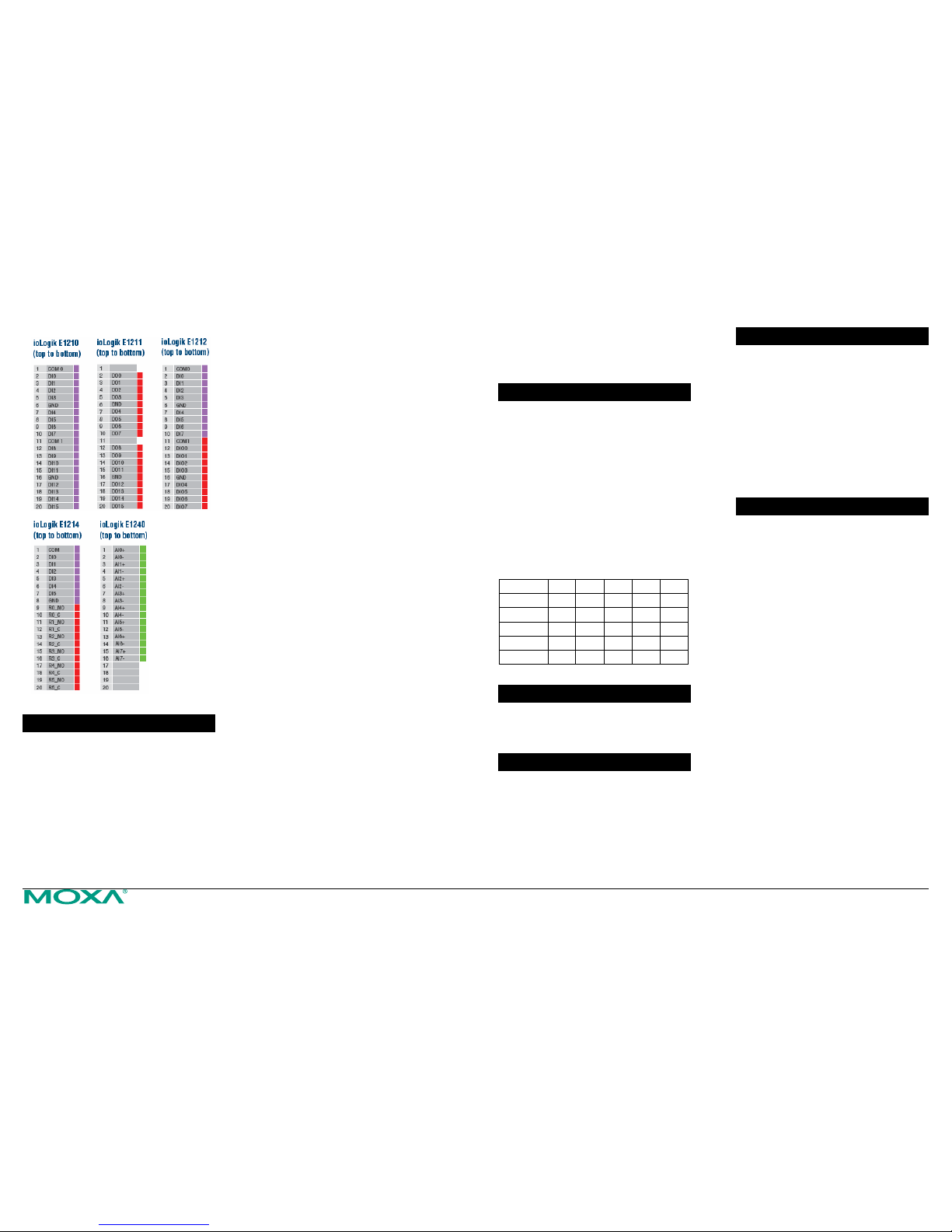
Pin Assignments
System Configuration
Configuration via Web Console
Main configuration of an ioLogik E1200 is via its
web console.
Default IP Address: 192.168.127.254
Subnet Mask: 255.255.255.0
Note: Be sure to configure the host PC’s IP
address to the same subnet as the ioLogik
E1200. For example, 192.168.127.253
ioSearch Utility
ioSearch is a search utility that helps user locate an
ioLogik E1200 on the local network.
Find the ioSearch utility in the Document and
Software CD \ Software \ ioSearch, or download the
latest version on Moxa website.
Load Factory Default
There are three ways to restore the ioLogik E1200
to the factory default.
1. Hold the RESET button for 5 seconds.
2. Right click the specified ioLogik in the
ioSearch utility and select “Reset to Default”.
3. Select the “Load Factory Default” at the web
console.
Modbus Address Table
Please refer to the user’s manual for details of the
ioLogik’s Modbus address, or refer to the start
address of the I/O channels in web console Æ
User-defined Modbus Addressing Æ Default
Address.
Active OPC Server Connection
Refer to the following steps to connect the ioLogik
E1200 to an Active OPC Server.
1. Disable the user-defined Modbus address
function.
2. Install the Active OPC Server Lite Package
from Document and Software CD Æ
Software Æ AOPC Lite Æ ActiveOPCSetup
Æ Install.exe
3. In web console Æ Active OPC Serve r
Settings Æ AOPC & I/O Settings, specify the
IP address where the Active OPC Server is
installed. Specify the I/O channels that need
to be added to the Active OPC Server Lite.
Submit the settings and then Save/Restart.
4. In web console Æ Active OPC Serve r
Settings Æ Create AOPC Tag, click the
“Create Tag” button.
5. Launch the Active OPC Server Lite from
Start Æ Programs Æ MOXA Æ IOServer Æ
ActiveOPC Æ ActiveOPC. Save the
configuration before exiting the Active OPC
Server Lite program.
ioLogik E1200 Series
Remote Ethernet I/O with 2-port Ethernet
Switch
Overview
The ioLogik E1200 series comes with 2
embedded Ethernet switch ports that can form a
daisy-chain topology, which is the easiest way to
add more Ethernet devices to a network or
connect your ioLogiks in series. Moxa’s free
Active OPC Server also offers active (or “push”)
communication with Moxa’s ioLogik series of
Ethernet I/O products for use with HMI/SCADA
systems, providing instant I/O status reports by
“Active Tags”. The event-driven active tags result
in an I/O response time that is 7 times faster than
other OPC Server packages. It also causes an
apparent 80% reduction in network traffic.
Model Selection:
ioLogik DI DO DIO Relay AI
E1210 16 -- -- -- -E1211 -- 16 -- -- -E1212 8 -- 8 -- -E1214 6 -- -- 6 -E1240 -- -- -- -- 8
Package Checklist
ioLogik E1200
Documentation and Software CD
Quick Installation Guide
Applications
Factory Facility Monitoring
Factory Environmental Monitoring
Remote Cabinet/Unmanned Site Monitoring
Lighting Control of Buildings
Machine Pre-installation
Features
Built-in 2-port Ethernet switch for
daisy-chain topologies
Free support of Moxa’s push-based Active
OPC Server Lite
• Seamlessly connect to any SCADA
system
• Save 80% on network bandwidth·
• I/O response that’s seven times faster·
User-defined Modbus/TCP addressing
MXIO programming library for Windows
and WinCE VB/VC.NET and Linux C APIs
Web configuration with Import/Export
function›
Specifications
Network:
2 x 10/100 Mbps switch ports, RJ45
I/O Control: Modbus/TCP, OPC Server,
MXIO(.NET) Library
Configuration: Web console, ioSearch
utility
System:
Power Input: 12 to 36 VDC
Power Consumption: 130 mA @ 24 VDC
Operating temperature: -10 to 60°C
(32 to 140°F)
Ambient Relative Humidity: 5 to 95%
Dimensions: 27 × 132 × 84 mm
Housing: ABS + PC
Weight: 180 ± 10 g
CE, FCC Class A approval
Warranty: 5 years (excluding E1214)
Digital Input:
Sensor Type: NPN, PNP, and Dry contact
I/O Mode: DI or Event Counter
Dry Contact Logic 0 short to GND;
Logic 1: open
Wet Contact:
• Logic 0: 0 to 3 VDC
• Logic 1: 10 to 30 VDC (DI COM to DI)
Counter/Frequency: 250 Hz, power off
storage
Digital Output:
I/O Mode: DO or Pulse Output
Pulse Wave Width/Frequency: 500 Hz
Over-current Limit: 400 mA (typical)
Page 2
ioLogik E1200 Series Quick Installation Guide ioLogik E1200 Series Quick Installation Guide
Relay Output:
Type: Form A (N.O.) relay outputs, 5A
Contact Rating: 5 A @ 30 VDC, 5 A @ 250
VAC, 5 A @ 110 VAC
Inductance Load: 2 A
Resistance Load: 5 A
Breakdown Voltage: 500 VAC
Relay On/Off Time: 10 ms, 5 ms (Max.)
Initial Insulation Resistance: 1G min. @
500 VDC
Expected Life: 100,000 times (Typical)
Initial Contact Resistance: 30 milli-ohms
(Max.)
Pulse Output: 0.3 Hz at rated load
Analog Input:
Type: differential input
Resolution: 16 bits
I/O Mode: Voltage / Current
Input Range: 0 to 10 VDC, 4 to 20 mA
Accuracy:
• ±0.1% FSR @ 25°C
• ±0.3% FSR @ -10 and 60°C
Sampling Rate (all channels): 12 samples
per second
Input Impedance: 10M ohms (min.)
Built-in Resistor for Current Input: 120
ohms
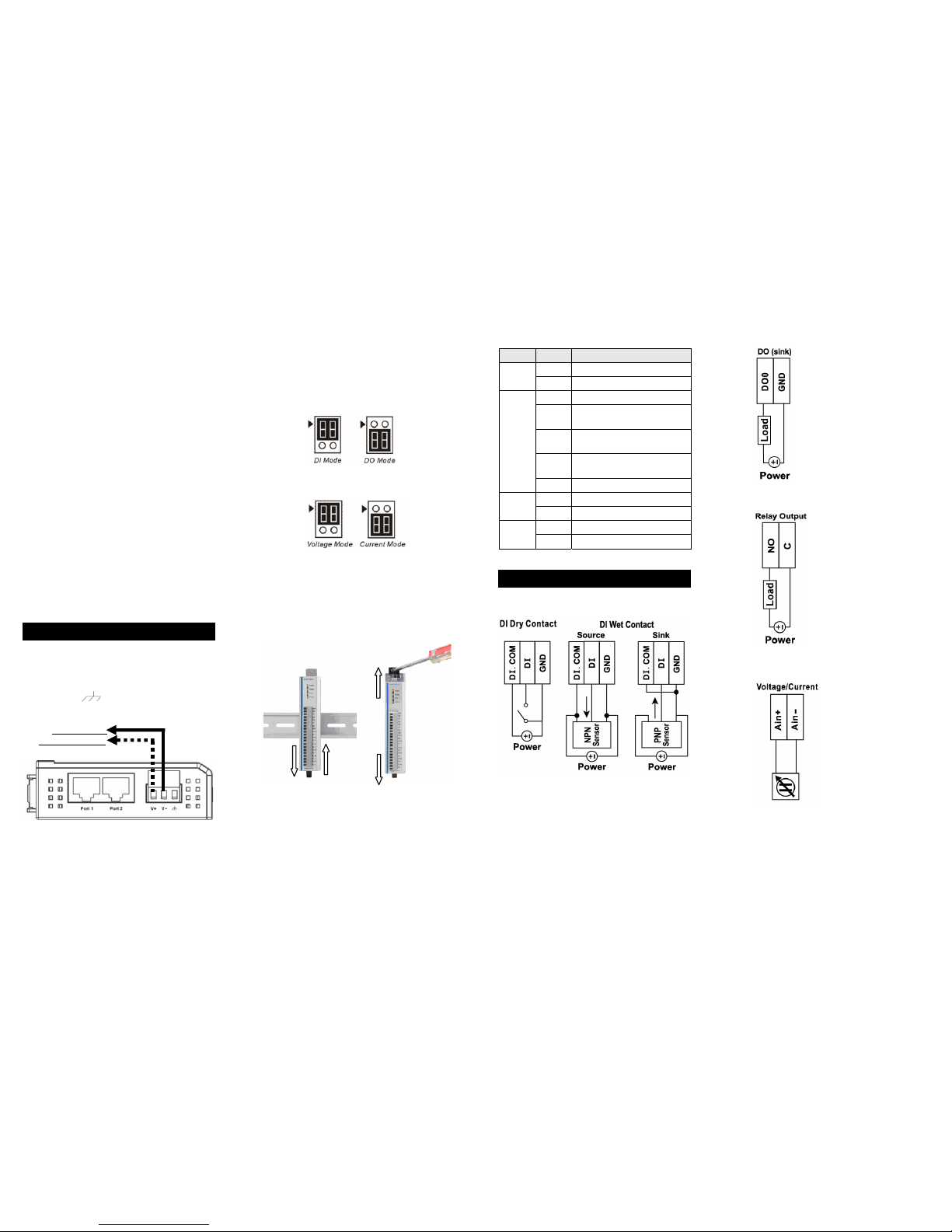
Installation
Power and Networking
Connect the +12 to +36 VDC power line to the
ioLogik E1200’s terminal block V+; connect the
ground from the power supply to the V-. Connect
the ground pin (
) if earth ground is available
Note: For safety reasons, the wires attached to
the power should be at least 2 mm in
diameter.
Jumper Settings
The ioLogik E1212 and E1240 require configuring
the jumpers inside the enclosure. Remove the screw
on the back panel and open the cover to configure
the jumpers.
For the ioLogik E1212, DIO mode configuration is
as follows: (default: DO Mode)
For the ioLogik E1240, analog mode configuration
is as follows: (default: Voltage Mode)
Mounting
The ioLogik E1200 is designed with a vertical form
factor, and can be used with both DIN-Rail and
Wall Mounting. When mounting on a rail, release
the bottom mounting Kit, install the ioLogik on the
rail, and restore the bottom mounting kit to fix the
ioLogik on the rail. When wall mounting, release
the both upper and bottom DIN-Rail kit.
The ioLogik E1200 has two built-in Ethernet switch
ports for connecting either a standard direct or
cross-over Ethernet cable to either RJ45 port.
LED Indicators
Type Color Description
Amber System power is ON
Power
Off System power is OFF
Green System is ready
Flashing
Flashes every 1 sec when the
“Locate” function is triggered
Flashing
Flashes every 0.5 sec when the
firmware is being upgraded
Flashing
A cycle of on/off period: 0.5
second shows “Safe Mode”
Ready
Off System is not ready.
Green Ethernet connection enabled
Port 1
Flashing Transmitting or receiving data
Green Ethernet connection enabled
Port 2
Flashing Transmitting or receiving data
I/O Wiring
Digital Input
Digital Output (Sink Type)
Relay Output (Form A)
Analog Input
Power Supply
+24VDC Nominal
(+12 to 36VDC)
 Loading...