

Moxa Technologies ioLogik 2542-GPRS, ioLogik 2512-GPRS, ioLogik 2512, ioLogik 2512-HSPA, ioLogik 2542-HSPA User Manual
...Page 1

ioLogik 2500 Series User’s Manual
Edition 7.0, March 2018
www.moxa.com/product
© 2018 Moxa Inc. All rights reserved.
Page 2

ioLogik 2500 Series User’s Manual
Moxa
Toll
Tel:
Fax:
Moxa China (Shanghai office)
Toll
Tel:
Fax:
Moxa Europe
Tel:
Fax: +49-89-3 70 03 99-99
Moxa As
Tel:
Fax: +886-2-8919-1231
Moxa India
Tel:
Fax:
The software described in this manual is fur nis he d und er a license agr eem e nt and may be used only in accor d ance
with the terms of that agreement.
Copyright Notice
© 2018 Moxa Inc. All rights reserved.
Trademarks
The MOXA logo is a registered trademark of Moxa Inc.
All other trademarks or registered marks in this manual belong to their res pec tive manufacturers.
Disclaimer
Information in this document is subject to c hange witho ut no ti c e and doe s not represent a commitment on the part of
Moxa.
Moxa provides this document as is, without warr anty of any kind, either expressed or implied, including, b ut not
limited to, its particular purpose. Mox a re serv e s the rig ht to mak e improv e ments and /or change s to this ma nual, or to
the products and/or the programs described in this manual, a t any time .
Information provided in this manual is intended to be accurate and reliable. However, Moxa assumes no responsibility
for its use, or for any infringements on the rights of third parties that ma y res ult from its use .
This product might include unintentional tec hnic al or typographical errors. Changes are periodic ally made to the
information herein to correct such errors, and these changes are incorporated into new editions of the public ation.
Technical Support Contact Information
www.moxa.com/support
Americas
-free: 1-888-669-2872
+1-714-528-6777
+1-714-528-6778
+49-89-3 70 03 99-0
-free: 800-820-5036
+86-21-5258-9955
+86-21-5258-5505
ia-Pacific
+886-2-8919-1230
+91-80-4172-9088
+91-80-4132-1045
Page 3

Table of Contents
1. Overview ........................................................................................................................................... 1-1
ioLogik 2500 Overview ........................................................................................................................ 1-2
Appearance ................................................................................................................................ 1-2
Dimensions Diagram .................................................................................................................... 1-3
Package Checklist ........................................................................................................................ 1-3
Product Features ......................................................................................................................... 1-3
I/O Channels Available on ioLogik 2500 Models ............................................................................... 1-3
Communication Interface ............................................................................................................. 1-4
ioLogik 2500 Ethernet Series Specifications ............................................................................................ 1-4
Common Specifications ................................................................................................................ 1-4
ioLogik 2512 Ethernet Specifications .............................................................................................. 1-5
ioLogik 2542 Ethernet Specifications .............................................................................................. 1-6
ioLogik 2500 HSPA/GPRS/WLAN Series Specifications.............................................................................. 1-7
Common Specifications ................................................................................................................ 1-7
ioLogik 2512 HSPA/GPRS/WLAN Specifications ................................................................................ 1-8
ioLogik 2542 HSPA/GPRS/WLAN Specifications ................................................................................ 1-9
2. Installation ....................................................................................................................................... 2-1
Hardware Installation .......................................................................................................................... 2-2
Installing the ioLogik 2500 on a DIN Rail ........................................................................................ 2-2
Removing the ioLogik 2500 from a DIN Rail .................................................................................... 2-2
Powering on the ioLogik 2500 ............................................................................................................... 2-3
Grounding the Unit ............................................................................................................................. 2-3
Installing a microSD Card and SIM Cards (cellular m ode ls only) ............................................................... 2-3
I/O Wiring Diagrams ........................................................................................................................... 2-4
I/O Wiring ......................................................................................................................................... 2-4
DI Channel ................................................................................................................................. 2-4
DO Channel (Sink Type) ............................................................................................................... 2-5
AI Channel ................................................................................................................................. 2-5
LED Indicators .................................................................................................................................... 2-6
Daisy-Chaining for I/O Expansion ......................................................................................................... 2-7
Reset to Factory Defaults ..................................................................................................................... 2-8
Network Installation ............................................................................................................................ 2-8
Ethernet Communication .............................................................................................................. 2-8
TCP/IP Settings ........................................................................................................................... 2-8
Serial Communication .................................................................................................................. 2-9
Software Installation—IO xp r ess U tility ................................................................................................. 2-10
System Requirements ................................................................................................................ 2-10
Installing IOxpress .................................................................................................................... 2-10
3. The IOxpress Utility .......................................................................................................................... 3-1
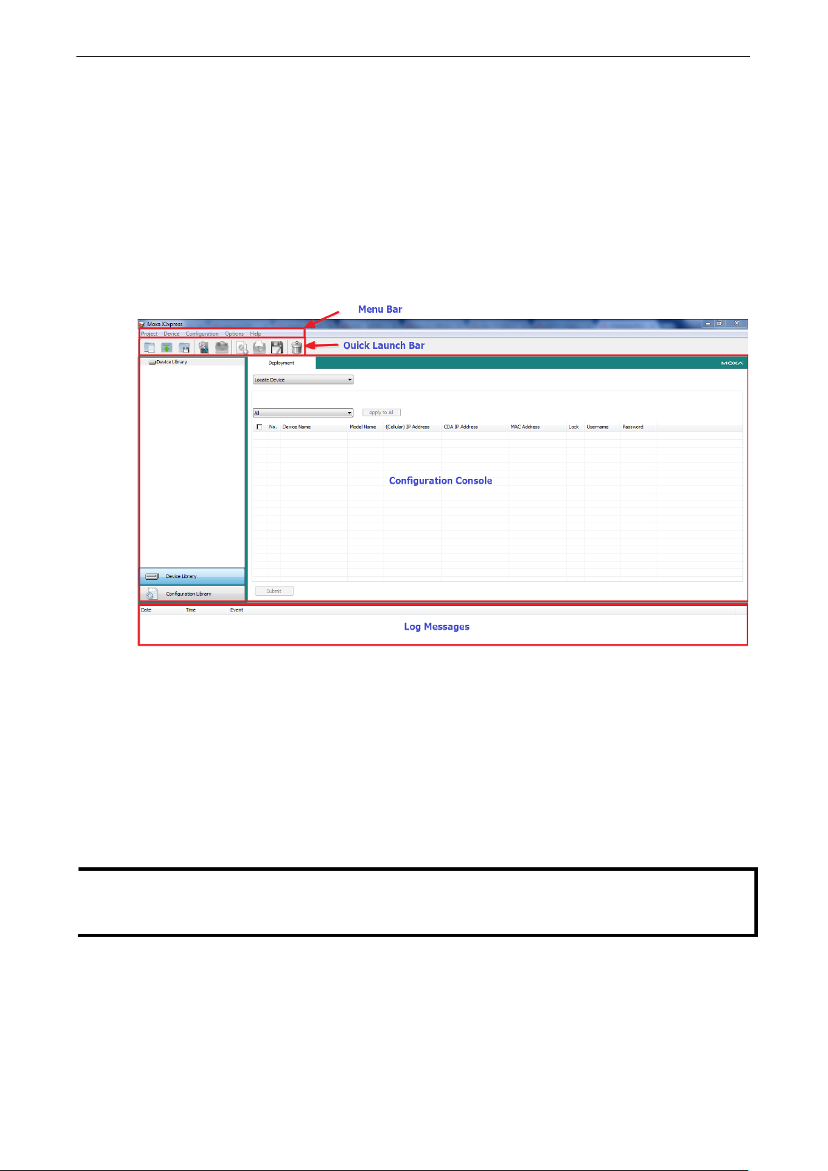
Application Interface ........................................................................................................................... 3-2
Main Screen................................................................................................................................ 3-2
Menu Bar ................................................................................................................................... 3-2
Using IOxpress ................................................................................................................................... 3-3
Configuration Flowchart ....................................................................................................................... 3-3
Configuration Library ................................................................................................................... 3-3
Device Library ............................................................................................................................. 3-3
4. Configuration Library ........................................................................................................................ 4-1
Introduction ....................................................................................................................................... 4-2
Saving Configurations as a Project ................................................................................................. 4-2
Adding an ioLogik 2500 Device to a Project .................................................................................... 4-2
Adding E1200 I/O Expansion Modules to a Project ........................................................................... 4-3
Duplicate Device Configuration for Mass Deployment ....................................................................... 4-4
Setting Up a Device ............................................................................................................................ 4-5
Settings Tab ...................................................................................................................................... 4-5
System ...................................................................................................................................... 4-5
Security ..................................................................................................................................... 4-6
Network ..................................................................................................................................... 4-8
I/O .......................................................................................................................................... 4-10
AOPC ....................................................................................................................................... 4-18
SNMP ....................................................................................................................................... 4-20
Modbus/TCP Slave ..................................................................................................................... 4-21
Modbus/TCP Master ................................................................................................................... 4-22
Serial Port (Port1/Port2)............................................................................................................. 4-25
Data Logging ............................................................................................................................ 4-28
Click&Go Plus ............................................................................................................................ 4-31
Click&Go Plus Tab ............................................................................................................................. 4-32
Click&Go Plus Simulator Tab .............................................................................................................. 4-32
Page 4

Peer-to-Peer Tab .............................................................................................................................. 4-32
General Settings ....................................................................................................................... 4-33
Peer-to-Peer Rule Settings ......................................................................................................... 4-34
5. Device Library ................................................................................................................................... 5-1
Introduction ....................................................................................................................................... 5-2
Auto-Searching for Online Devices ........................................................................................................ 5-3
First Time Searching for Devices ................................................................................................... 5-3
Conducting another Search for Online Devic e s ................................................................................ 5-3
Deployment ....................................................................................................................................... 5-6
Update Configuration to Device ..................................................................................................... 5-7
Get Configuration from Device ...................................................................................................... 5-7
Update Firmware ......................................................................................................................... 5-7
Set Device Date & Time ............................................................................................................... 5-8
Retrieve System Log .................................................................................................................... 5-8
Restart Device ............................................................................................................................ 5-8
Load Factory Default .................................................................................................................... 5-8
Change IP Address ...................................................................................................................... 5-8
Change Device Name ................................................................................................................... 5-8
Web Console ...................................................................................................................................... 5-8
Web Console Functions ........................................................................................................................ 5-9
User Interface Introduction ........................................................................................................... 5-9
System Information Panel .......................................................................................................... 5-10
Menu Panel and Web Pages ........................................................................................................ 5-10
6. Cellular Network Setup and Configuration (for cellular models) ....................................................... 6-1
IOxpress Settings for a Cellular Network ................................................................................................ 6-2
Select Network Interface .............................................................................................................. 6-2
Cellular ...................................................................................................................................... 6-3
Cellular Network Connection .............................................................................................................. 6-10
MX-AOPC Server (for SCADA/HMI user s) ...................................................................................... 6-10
With DDNS (for SCADA/HMI users) .............................................................................................. 6-11
Moxa Cellular Data Access Utility (for mobile dev ic es/PCs) .............................................................. 6-11
7. Wireless LAN Networ k S et up and Conf i gur a tion (for wireless LAN m od els) ...................................... 7-1
Deploying the ioLogik 2500-WL1........................................................................................................... 7-2
IOxpress Settings for a Wireless LAN Network ........................................................................................ 7-2
Wireless LAN .............................................................................................................................. 7-2
A. Network Port Usage .......................................................................................................................... A-1
B. Modbus/TCP D efa ult Addre ss Mappings ............................................................................................ B-1
ioLogik 2512 Series Modbus Address and Register Map............................................................................ B-1
ioLogik 2542 Series Modbus Address and Regis ter Map............................................................................ B-2
C. RESTful API Default Add re ss Ma ppings ............................................................................................. C-1
API List ............................................................................................................................................. C-1
Response Code ................................................................................................................................... C-6
Page 5

1
1. Overview
The ioLogik 2500 is a smart remote I/O product with unique hard w are and softw are des igns, m ak i ng it an
ideal solution for a variety of industrial d ata acquis iti o n app lic ati o ns . The ioLogik 2500’s hardware design
includes a 4-port unmanaged Etherne t s w itc h and 2 ser ial ports , enab ling the ioLogik 2500 to seamlessly
connect to a variety of field devices. One of the Ethernet ports ca n be used to link to 8 daisy-chained
ioLogik E1200 expansion modules to provide more than 100 c hanne ls . The ioLogik 2500 acts as the “head”
unit, with Click&Go Plus logic used to control the entire I /O array. Mo st importantly, the ioLogik 2500’s
single IP is all that’s required to connect the entir e I/O arr ay to your netwo rk , providing the perfect solution
for industrial field sites that have an insuf f i c ie nt number of IP addre sse s .
For cellular connections, the ioLogik 2500 supports Moxa’s patented MX-AOPC Server with push
communications technology, and pr ov id es an econo mical solution for accessing multiple remote I/O devi ces
connected to the same private IP network, which itself links to the outside world over a cellular connection
using dynamic IP addresses.
The following topics are covered in this chapter:
ioLogik 2500 Overview
Appearance
D im e ns io ns D iagr am
Pac k a g e Checklist
Pr oduct Features
I/O Channels Available on ioLogik 2500 Models
Communication Interface
ioLogik 2500 Ethernet Seri es Specif ic a tio ns
Common Specifications
io Logik 2512 Ethernet Specifications
ioLogik 2542 Ethernet Specifications
ioLogik 2500 HSPA/GPRS/ WL AN S erie s Spec ific a tio n s
Common Specifications
ioLogik 2512 HSPA/GPRS/WLAN Specifications
ioLogik 2542 HSPA/GPRS/WLAN Specifications
Page 6

ioLogik 2500 Series Overview
1-2
The ioLogik
box, dramatically reducing the
devices from multiple vendors.
Micro SD card (supports cards with up to 32 GB of storage space), and the
ioLogik 2500
control logi
systems. As a rugged industrial device, the ioLogik 2500 operates reliably
at a wide range of temperatures, and is well suited for hard
wire remote
monitoring and
pipelines.
Top View
Front View
ioLogik 2500 Overview
2500 combines a remote I/O device and data logger into one
amount of effort required to integr a te
I/O and serial data can be logged onto a
can be programmed with Moxa’s convenient Click&Go™ Plus
c, which can be used to easily construct customized control
-to-
alarm applications at unmanned sites like riversides and
Appearance
Page 7
ioLogik 2500 Series Overview
1-3
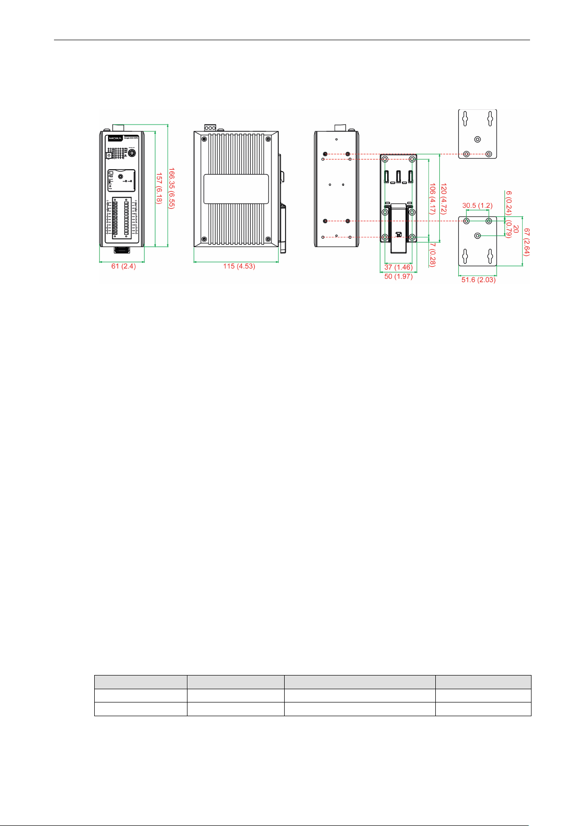
Dimensions Diagram
Units: mm (in)
Package Checklist
The ioLogik 2500 is shipped with the following ite ms :
• ioLogik 2500 device
• 2 RJ45-to-DB9 connection cables (CBL-RJ45M9-150)
• 1 antenna (only for wireless models)
• Quick installation guide (printed)
NOTE: Please notify your sales represe ntati v e if any of the above item s are missing or d amage d .
Product Features
• Supports cellular (HSPA/GPRS), Ethernet, and serial communication (ioLog ik 2500-HSPA/GPRS only)
• New Click&Go Plus logic provides powerful front-end intelligence
• Supports wireless LAN communication (ioLo g i k 2500 -WL1 only)
• 4-port unmanaged switch built in for linking to Etherne t devices
• Optimized I/O expansion port for daisy chaining up to 8 ioLogik E1200 units
• 2 serial ports (RS-232/422/485) for connecting field devices
• Built-in data logger supports an FTP server/client and microSD™ card with up to a 32 GB
• Transforms Modbus RTU into Modbus TCP or Active Tags
• Active communication with patented MX -AOPC UA Server
• Smart alarm management: Email, SNMP traps, TCP, UDP, SMS
• Wide operating temperature: -40 to 75°C (-40 to 167°F)
I/O Channels Available on ioLogik 2500 Models
Model Name Digital Inputs DI/DO (DIO) Configurable Analog Inputs
ioLogik 2512 8 8 –
ioLogik 2542 – 12 4
Page 8

ioLogik 2500 Series Overview
1-4
LAN
Ethernet:
• 4 switched 10/ 1 00 Mbps RJ45 ports
• 1 optimized port for faster
Note: The optimized daisy
Protection:
Protocols:
Serial
Interface:
Parity:
Data Bits:
Stop Bits:
Flow Control:
Baudrate:
Protocols:
Physical Characteristics
Wiring:
Dimensions:
Weight:
Mounting:
Storage
Expansion Slot:
Note: For units operating in extreme temperature s , ind us trial
required.
Environmental
Operating Temperature:
Standard Models:
Wide Temp. Models:
Storage Tem perature:
Ambient Relative Hu midity:
Shock:
Vibration
Altitude:
Note: Please contact Moxa if you require produc ts g uarante ed to f unc tion properly at higher altitudes.
Communication Interface
Model Name Communication Interfac e
ioLogik 2512
ioLogik 2542
ioLogik 2512-GPRS
ioLogik 2542-GPRS
ioLogik 2512-HSPA
ioLogik 2542-HSPA
ioLogik 2512-WL1
ioLogik 2542-WL1
Serial / Ethernet
Serial / Ethernet / GPRS (2G)
Serial / Ethernet / GPRS (2G) /HSPA (3G)
Serial / Ethernet / Wireless LAN
ioLogik 2500 Ethernet Series Specifications
Common Specifications
downstream communications with daisy-chaine d ioLogik E1200 units
-chain port is not supported by the ioLogik E1261W-T, E1261H-T, or E1263H-T.
1.5 kV magnetic isolation
Modbus/TCP (slave), TCP/IP, UDP, DHCP, BOOTP, SNMP, HT TP, C GI, SNTP, SMTP
2 RS-232/422/485 (software sele c t a b l e ) RJ45 ports
None , O dd, Even
5, 6, 7, 8
1, 2
None, RTS/CTS, XON/XOFF
300 to 11520 0 bps
Modbus/RTU (master/gateway), serial tunnel mod e (clie nt/s e rver)
I/O cable max. 14 AWG
61 x 157 x 115 m m (2.4 x 6.18 x 4.53 in)
Under 1265 g (2.79 lb)
DIN-rail (standard), wall (with o p tional kit)
Up to 32 GB microSD™ memory card (SDHC compatible)
-grade, wide-temperature SD cards are
Limits
-10 to 60°C (14 to 140°F)
-40 to 75°C (-40 to 167°F)
-40 to 85°C (-40 to 185° F)
5 to 95% (non-condensing)
IEC 60068-2-27
: IEC 60068-2-6
Up to 2000 m
Page 9

ioLogik 2500 Series Overview
1-5
Standards and Cer t ifications
Safety:
EMC:
EMI:
EMS:
IEC 61000
IEC 61000
IEC 61000
IEC 61000
IEC 61000
IEC 61000
Hazardous Location:
Green Product:
Note: Please check Moxa’s website for the most up
Warranty
Warranty Period:
Details: See www .mox a.com/warranty
Inputs and Outputs
Digital Inputs:
Configurable DIOs (by software): 8 channels
Isolation:
Digital Input
Sensor Type:
I/O Mode:
Dry Contact:
•
• Off: open
Wet Contact (DI to COM):
• On: 10 to 30 VDC
• Off: 0 to 3 VDC
Common Type:
Counter Frequenc y:
Digital Filtering Time Interval:
Digital Output
Type:
I/O Mode: DO or Pulse Output
Pulse Output Freq uenc y:
Over
Over
Over
Current Rating: 500 mA per channel @ 25°C
DIO Output Leakage Current:
Power Requirements
Input Voltage:
Input Curre nt:
MTBF (mean time between failures)
Time:
Standard:
UL 508
EN 61000-6-2/6-4
CISPR 32, FCC Part 15B Class A
-4-2 ESD: Contact: 4 kV; Air: 8 kV
-4-3 RS: 80 MHz to 1 GHz: 10 V/m
-4-4 EFT: Power: 1 kV; Signal: 0.5 kV
-4-5 Surge: Power: 1 kV
-4-6 CS: 3 V
-4-8
Class 1 Division 2; ATEX Zone 2
RoHS, C RoHS, WEEE
-to-date certification status.
5 years
ioLogik 2512 Ethernet Specifications
8 channels
3k VDC or 2k Vrms
Wet Contact (NPN or PNP) and Dry Contact
DI or Event Counter
On: short to GND
8 points per COM
2.5 kHz
Software configurable
Sink
5 kHz
-Voltage Protection: 45 VDC
-Current Protection: 1.5 A per channel @ 25°C
-Temperature Shutdown: 175°C (min.)
9 to 48 VDC
274 mA @ 24 VDC
467,032 hrs
Telcordia SR332
< 1 mA @ 30 VDC
Page 10

ioLogik 2500 Series Overview
1-6
Inputs and Outputs
Configurable DIOs
Analog Inputs:
Isolation:
Digital Input
Sensor Type:
I/O Mode:
Dry Contact:
• On: short to GND
• Off: open
Wet Contact (DI to
• On: 10 to 30 VDC
• Off: 0 to 3 VDC
Common Type:
Counter Frequenc y:
Digital Filtering Time Interval:
Digital Output
Type:
I/O Mode:
Pulse Output Freq uenc y:
Over
Over
Over
Current Rating:
DIO Output Leakage Current:
Analog Input
Type:
Resolution:
I/O Mode:
Input Ran g e:
Accuracy:
• ±0.1% FSR @ 25° C
• ±0.3% FSR @
• ±0.5% FSR @
Sampling Rate
• All channels: 400 samples/sec
• Per channel: 100 samples/sec
Input Impedance:
Built
Power Requirements
Input Voltage:
Input Curre nt:
MTBF (mean time between failures)
Time:
Standard:
ioLogik 2542 Ethernet Specifications
(by software): 12 channels
4 channels
3k VDC or 2k Vrms
Wet Contact (NPN or PNP) and Dry Contact
DI or Event Counter
COM):
6 points per COM
2.5 kHz
Software configurable
Sink
DO or Pulse Output
5 kHz
-Voltage Protection: 45 VDC
-Current Protection: 1.5 A per channel @ 25°C
-Temperature Shutdown: 175°C (min.)
500 mA per channel @ 25°C
< 1 mA @ 30 VDC
Differential input
16 bits
Voltage / Current (software selectable)
±10 V, 0 to 10 V, 0 to 20 mA, 4 to 20 mA, 4 to 20 mA (burnout detection)
-10 and 60°C
-30 and 70°C
:
1 mega-ohm (min.)
-in Resistor for Current Input: 120 ohms
9 to 48 VDC
358 mA @ 24 VDC
375,439 hrs
Telcordia SR332
Page 11

ioLogik 2500 Series Overview
1-7
Cellular
Standards:
HSPA Model Band Options:
• UMTS/HSPA+: five
•
GPRS Model Band Options:
SIM Control Voltage:
SIM Format:
Connector Type
WLAN
Standards:
• IEEE 802.11b/g for wireless LAN
•
Spread Spectrum and Modulation (typical):
• DSSS with DBPSK, DQPSK, CCK
• OFDM with BPSK, QPSK, 16QAM, 64QAM
• 802.11b: CCK @ 11/5.5 Mbps, DQPSK @ 2 Mbps, DBPSK @ 11 Mbps
• 802.11g: 64 QA M @ 54/48 Mbps, 16QAM @ 36/24 Mb p
Operating Channels (central frequency):
• US: 2.412 to 2.462 GHz (11 channels)
• EU: 2.412 to 2.472 GHz (13 channels)
Security:
• 64
• Full WPA/WPA2 Personal
Transmission Rates:
• 802.
• 802.11g: 6, 9, 12, 18, 24, 36, 48, 54 Mbps
TX Transmit Power:
• 802.11b: Typ . 18±1.5 dBm @ 1 to 11 Mbps
• 802.11g: Typ . 18±1.5 dBm @ 6 to 24 Mbps, Typ. 17±1.5 dBm @ 36 Mbps, Typ. 16± 1. 5 dBm @ 48 Mbps,
Typ. 16±1.5 dBm @ 54 Mbps
R
• 802.11b:
• 802.11g:
Connector Type:
LAN
Ethernet:
• 4 switched
• 1 optimized port for faster downstream communic ati o ns with dais y
Note: The optimized daisy
Protection:
Protocols:
Serial
Interface:
Parity:
Data Bits:
Stop Bits: 1, 2
ioLogik 2500 HSPA /GPRS/WLAN Series Specifications
Common Specifications
GSM/GPRS/EDGE/UMTS/HSPA+
-band 800/850/900/1900/2100 MHz
GSM/GPRS/EDGE: quad-band 850/900/1800/1900 MHz
GSM/GPRS/EDGE: quad-band 850/900/180 0/1900 MHz
3/1.8 V
Full size
: SMA female
IEEE 802.11i for wireless security
s, QPSK @ 18/12 Mbps, BPSK @ 9/6 Mbps
-bit and 128-bit WEP encryption
11b: 1, 2, 5.5, 11 Mbps
X Sensitivity:
-97 dBm @ 1 Mbps, -94 dBm @ 2 Mbps, -92 dBm @ 5.5 Mbps, -90 dBm @ 11 Mbps
-88 dBm @ 6 to 24 Mbps, -85 dBm @ 36 Mbps, -75 dBm @ 48 Mbps, -70 dBm @ 54 Mbps
RP-SMA Female
10/100 Mbps RJ45 ports
-chained ioLogik E1200 units
-chain port is not supported by the ioLogik E1261W-T, E1261H-T, or E1263H-T.
1.5 kV magnetic isolation
Modbus/TCP (slave), TCP/IP, UDP, DHCP, BOOTP, SNMP, HT TP, C GI, SNTP, SMTP
2 RS-232/422/485 (software sele c t a b l e ) RJ45 ports
None , O dd, Even
5, 6, 7, 8
Page 12

ioLogik 2500 Series Overview
1-8
Flow Control:
Baudrate:
Protocols:
Physical Characteristics
Wiring:
Dimensions:
Weight: Under 1265 g (2.79 lb)
Mounting:
Storage
Expansion Slot:
Note: For units operating in extreme temperature s , ind us trial
required.
Environmental Limits
Operating Temperature:
Standard Models:
Wide Temp. Models:
Storage Tem perature:
Ambient Relative Hu midity: 5 to 95% (non-condensing)
Shock:
Vibration:
Altitude:
Note: Please contact Moxa if you require produc ts g uarante ed to f unc tion properly at higher altitudes.
Standards and Cer t ifications
Safety:
EMC:
EMI:
EMS:
IEC 61000
IEC 61000
IEC 61000
IEC 61000
IEC 61000
IEC 61000
Radio:
Hazardous Location:
Green Product:
Note: Please check Moxa’s website for the most up
Warranty
Warranty Period:
Details: See www .mox a.com/warranty
Inputs and Outputs
Digital Inputs:
Configurable DIOs (by software): 8 channels
Isolation:
Digital Input
Sensor Type:
I/O Mode:
Dry Contact:
• On: short to GND
• Off: open
None, RTS/CTS, XON/XOFF
300 to 11520 0 bps
Modbus/RTU (master/gateway), serial tunnel mod e (clie nt/s e rver)
I/O cable, 14 AWG (max.)
61 x 157 x 115 m m (2.4 x 6.18 x 4.53 in)
DIN rail (standard), wall (optional)
Up to 32 GB microSD™ memory card (SDHC compatible)
-grade, wide-temperature SD cards are
-10 to 60°C (14 to 140°F)
-30 to 70°C (-22 to 158°F)
-40 to 85°C (-40 to 185° F)
IEC 60068-2-27
IEC 60068-2-6
Up to 2000 m
UL 508
EN 61000-6-2/6-4
CISPR 32, FCC Part 15B Class A
-4-2 ESD: Contact: 4 kV; Air: 8 kV
-4-3 RS: 80 MHz t o 1 GHz: 3 V/m
-4-4 EFT: Power: 1 kV; Signal: 0.5 kV
-4-5 Surge: Po wer 2 kV
-4-6 CS: 3 V
-4-8
R&TTE: EN 62311, EN 300 328, EN 301 489-1, EN 301 489-17, EN 301 893; NCC; VCCI
Class 1 Division 2; ATEX Zone 2
RoHS, C RoHS, WEEE
-to-date certification status.
5 years
ioLogik 2512 HSPA/GPRS/WLAN Specifications
8 channels
3k VDC or 2k Vrms
Wet Contact (NPN or PNP) and Dry Contact
DI or Event Counter
Page 13

ioLogik 2500 Series Overview
1-9
Wet Contact (DI to COM):
• On: 10 to 30 VDC
• Off: 0 to 3 VDC
Common Type:
Counter Frequenc y:
Dig
Digital Output
Type:
I/O Mode:
Pulse Output Freq uenc y:
Over
Over
Over
Current Rating:
DIO Output Leakage Current:
Power Requirements
Input Voltage:
Input Curre nt:
• HSPA Model: 390 mA @ 24 VDC
• GPRS Model: 416 mA @ 24 VDC
• WL1 Model: 328 mA @ 24 VDC
MTBF (mean time between failures)
Time:
• HSPA model: 378,154 hrs
• GPRS model: 403,452 hrs
• WL1 model: 400,469 hrs
Standard:
Inputs and Outputs
Configurable DIOs (by software):
Analog Inputs:
Isolation: 3k VDC or 2k Vrms
Digital Input
Sensor Type:
I/O Mode:
Dry Contact:
• On: short to GND
• Off: open
Wet Contact (DI to COM):
• On: 10 to 30 VDC
• Off: 0 to 3 VDC
Common Type:
Counter Frequenc y:
Digital Filtering Time Interval:
Digital Output
Type:
I/O Mode:
Pulse Output Freq uenc y:
Over
Over
Over
8 points per COM
2.5 kHz
ital Filtering Time Interval: Softw are configurable
Sink
DO or Pulse Output
5 kHz
-Voltage Protection: 45 VDC
-Current Protection: 1.5 A per channel @ 25°C
-Temperature Shutdown: 175°C (min.)
500 mA per channel @ 25°C
< 1 mA @ 30 VDC
9 to 48 VDC
Telcordia SR332
ioLogik 2542 HSPA/GPRS/WLAN Specifications
12 channels
4 channels
Wet Contact (NPN or PNP) and Dry Contact
DI or Event Counter
6 points per COM
2.5 kHz
Software configurable
Sink
DO or Pulse Output
5 kHz
-Voltage Protection: 45 VDC
-Current Protection: 1.5 A per channel @ 25°C
-Temperature Shutdown: 175°C (min.)
Page 14

ioLogik 2500 Series Overview
1-10
Current Rating:
DIO Output Leakage Current:
Analog Input
Type:
Resolution:
I/O Mode:
Input Ran g e: ±10 V, 0 to 10 V, 0 to 20 mA, 4 to 20 mA, 4 to 20 mA (burnout detection)
Accuracy:
• ±0.1% FSR @ 25° C
• ±0.3% FSR @
• ±0.5% FSR @
Sampling
• All channels: 400 samples/sec
• Per channel: 100 samples/sec
Input Impedance:
Built
Power Requirements
Input Voltage:
Input Curre nt:
• HSPA Model: 442 mA @ 24 VDC
• GPRS
• WL1 Model: 406 mA @ 24 VDC
MTBF (mean time between failures)
Time:
• HSPA model: 378,154 hrs
• GPRS model: 403,087 hrs
• WL1 model: 331,222 hrs
Standard: Telcordia SR332
500 mA per channel @ 25°C
< 1 mA @ 30 VDC
Differential input
16 bits
Voltage / Current (software selectable)
-10 and 60°C
-30 and 70°C
Rate:
1M ohms (min.)
-in Resistor for Current Input: 120 ohms
9 to 48 VDC
Model: 494 m A @ 24 VDC
Page 15

2
2. Installation
In this chapter, we provide instructions on how to instal l the io Log ik 2500 I/O ser ver to connect to the
network and serial devices.
The following topics are covered in this chapter:
Hardware Installation
Installing the ioLogik 2500 on a DIN Rail
R e moving the ioLogik 2500 from a DIN Rail
Powering on the ioLogik 2500
Grounding the Unit
Installing a microSD Card and SIM Cards (cellular models only)
I/O Wiring Diagrams
I/O Wiring
DI Channel
DO Channel (Sink Type)
AI Channel
LED Indicators
Daisy-Chaining for I/O Expansion
Reset to Factory Defaults
Network Install ati on
Ethe r ne t Co mm unic ation
TCP/IP Settings
Serial Communication
Software Install at ion —IOxpress Utility
System Requirements
Installing IOxpress
Page 16
ioLogik 2500 Series Installation
2-2
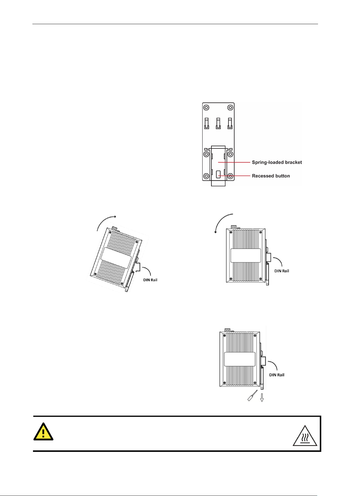
STEP 1:
place, push the recessed button to release it. Onc e
released, you should feel some resistance from the
spring as you slid
millimeters in each direction.
STEP 2:
of the attachment plate’s slot.
STEP 3:
place along the rail, as shown below.
To remove the ioLogik 2500 from a DIN rail, use a
screwdriver to pull down the spring
until it locks in place, as shown in the diagram at the
right. Next, rotate the bottom of the ioLogik 2500
upwards until y
WARNING
This equipment is intended to be used in Restricted Acc ess Lo c ations. External metal parts
be
Hardware Installation
Installing the ioLogik 2500 on a DIN Rail
The DIN-rail attachment plate should alr e ady b e fixed to the back panel of your ioLogik 2500. If you need
to reattach the plate, be sure the spring-loaded br ack e t is oriented tow ard s the bo tto m , as shown in the
figures below.
If the spring-loaded bracket is locked in
e the bracket up and down a few
Insert the top of the rail into the upper lip
The attachment unit should now snap into
Removing the ioLogik 2500 from a DIN Rail
-loaded bracke t
ou can remove it from the DIN rail.
hot! Maintenance personnel should wear protective gear before to uching the outside surface.
will
Page 17
ioLogik 2500 Series Installation
2-3
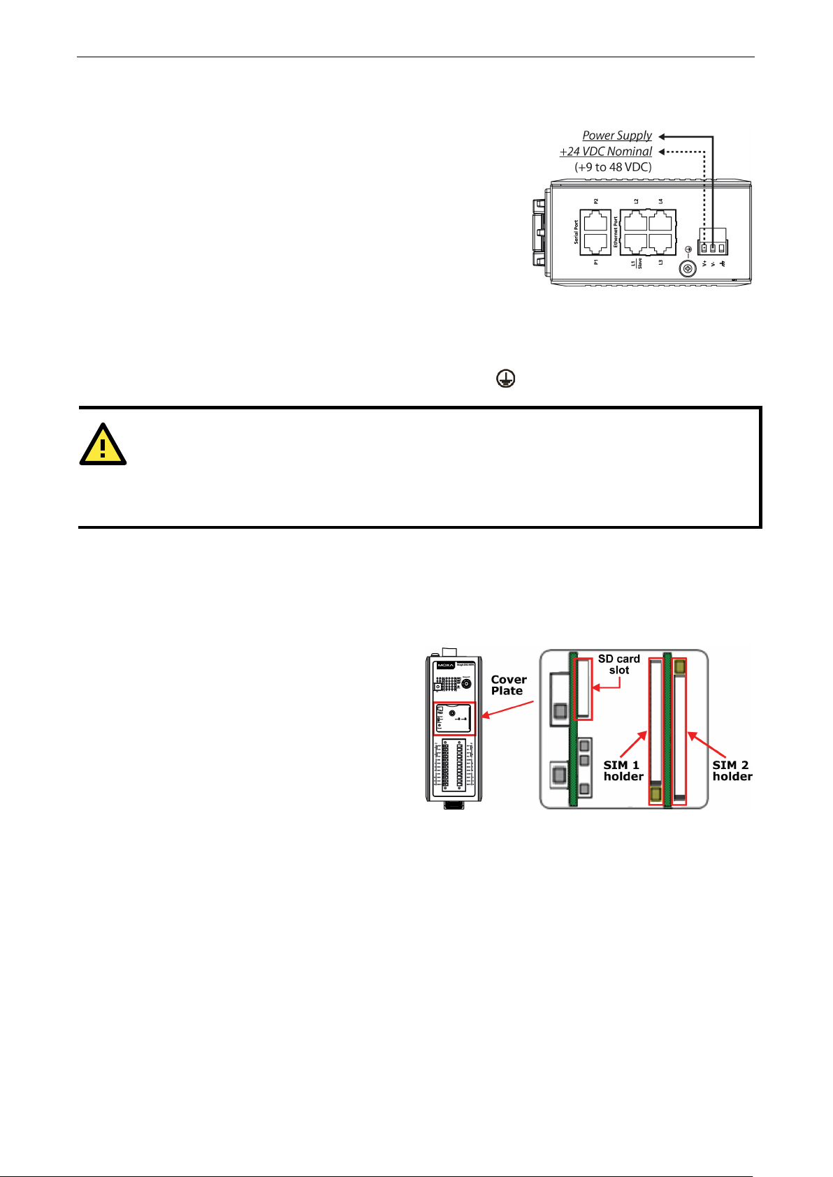
The ioLogik 2500 can re ceive power from a 9 to 48 VDC power
source. Input power is applied to the positive (V+) and negative
(V
After connecting the ioLogik 2500 to the power supply, it will take
30 to 60 seconds for the operating system to boot up. The green
Ready LED will illuminate continuously until the operating system
is ready.
ATTENTION
Be sure to note
codes dictating the maximum current allow able for each wire size. If current
the wi
connecting the power supply should be at least 2 mm in diameter (e.g., 12 gauge).
The ioLogik 2500 supports a single microSD card
and two SIM cards (cellular models only). The
card slots are located inside the ioLogik 2500 , as
shown here. The card slot is hidden
cover plate attached by a screw that must first
be removed before
After removing the screw holding the cover plate
in place you can insert or remove the
microSD/SIM cards. Be sure to refasten the
cover plate when you are done.
Powering on the ioLogik 2500
-) terminals on the connector.
Grounding the Unit
The ioLogik 2500 is equipped with a ground connector labeled .
res will overheat, and may cause serious damage to the equipment. For safety reasons, wires
the maximum possible current for each power wire and common wire. Observe a ll elec tr ic a l
s exceed the maximum rating
Installing a microSD Card and SIM Cards (cellular models only)
beneath a
the slot can be accessed.
Page 18
ioLogik 2500 Series Installation
2-4
I/O Wiring Diagrams
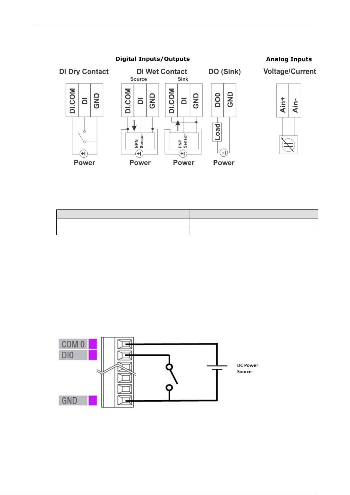
I/O Wiring
Follow the wiring guide for the I/O channels:
Item Suggestion
Wire range 16 to 26 AWG
Screw Torque 3 lb-inch
DI Channel
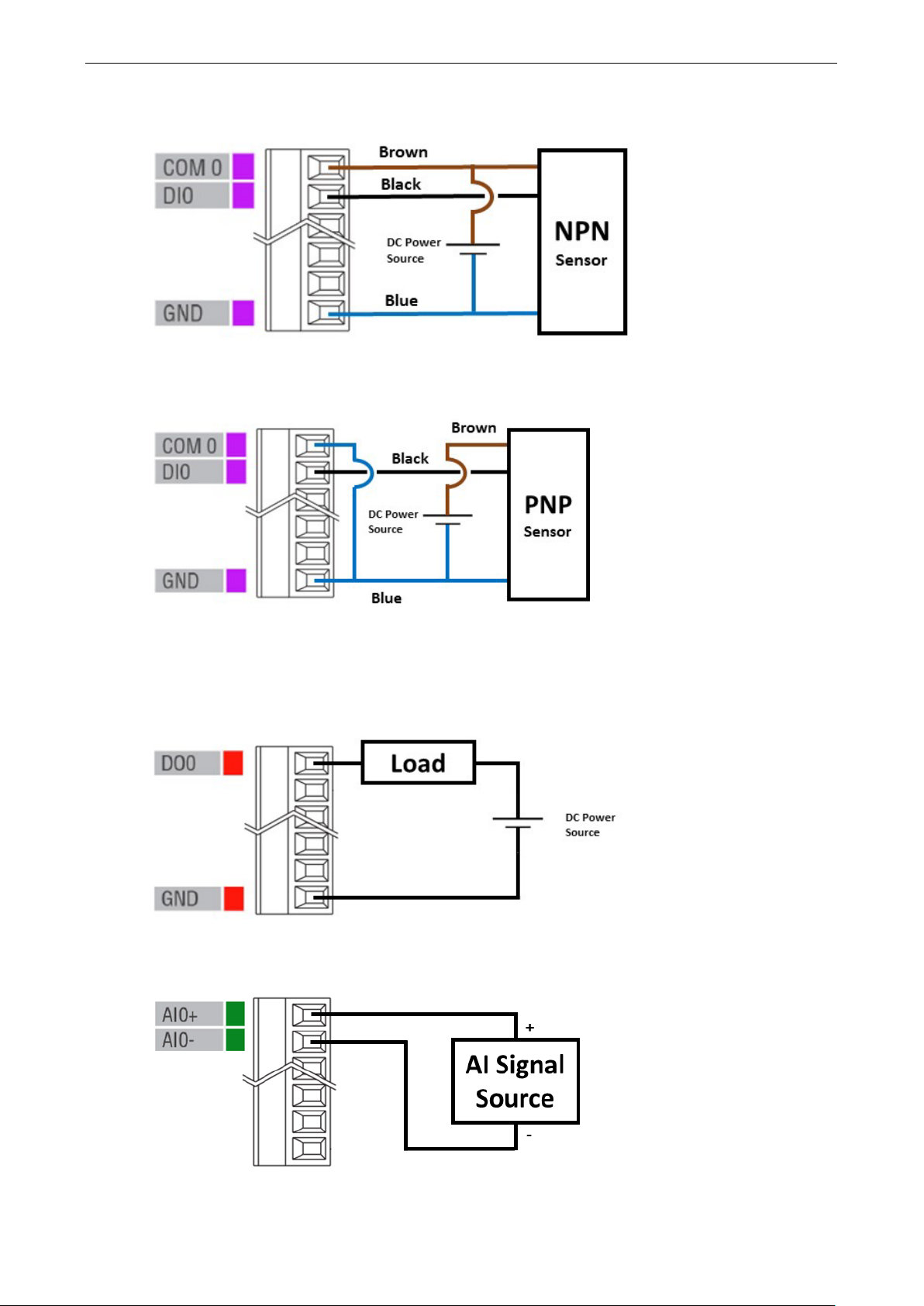
There are two categories of DI contact: Dry Contact and Wet Contact. Fo llow the wiring diagram for the
particular component you are using.
A Dry Contact is a contact that works without a power source: buttons, switches, etc.
A Wet Contact is a contact that requires a power source to work: proximity sensors, motion sensors, etc.
Check the sensor type (NPN, PNP) and follow the corresponding wiring sho wn belo w.
DI Dry Contact
Page 19
ioLogik 2500 Series Installation
2-5
DI Wet Contact (NPN)
DI Wet Contact (PNP)
DO Channel (Sink Type)
The DIO channels of this series can be used as DI channels or DO channels. The wiring diagram for DO
channels, which are sink type , is shown below:
AI Channel
Page 20

ioLogik 2500 Series Installation
2-6
Green
System is ready
LED Indicators
Type Color Description
Power
(PWR)
Ready
(RDY)
Ethernet Port
(L1/L2/L3/L4)
Serial Port
(P1/P2)
SD (Micro SD) Green SD card inserted
I/O Channel Status*
(0 to 15)
W.Link** Green Wireless connection established
Signal Status** Off No signal, or No SIM card
*Use the rotary switch to select which module’s I/O channe l s tatus is dis p laye d .
0 = ioLogik 2500
1 to 8 = E1200 expansio n
9 to F = Reserved
**Wireless models only
Green System power is ON
Off System power is OFF
Red System error
Green (blinking once per sec.) Locating device
Red (blinking once per sec.) Expansion Runtime Error
Green/Red (blinking once per 0.5 sec.) Safe Mode
Off System is not ready
Green Ethernet connection enabled at 100 Mbps
Amber Ethernet connection enabled at 10 Mbps
Blinking Data is being transmitted
Off Disconnected
Green Tx
Amber Rx
Blinking Data is being transmitted
Off Disconnected
Off SD card not inserted
Green Channel ON or Counter/Pulse signal
Off Channel OFF or No Counter/Pulse signal
Off Off
1 LED Weak or insufficient (SMS only)
2 LEDs Average (good for cellular connections)
3 LEDs Excellent signal
Page 21
ioLogik 2500 Series Installation
2-7
NOTE
Expansion units must be replaced with the same model of expans i o n unit. I
different expansion unit model, yo u must first change the relevant IOxpress settings.
ioLogik 2500
ioLogik E1200
ioLogik E1200
ioLogik E1200
ioLogik E1200
ioLogik E1200
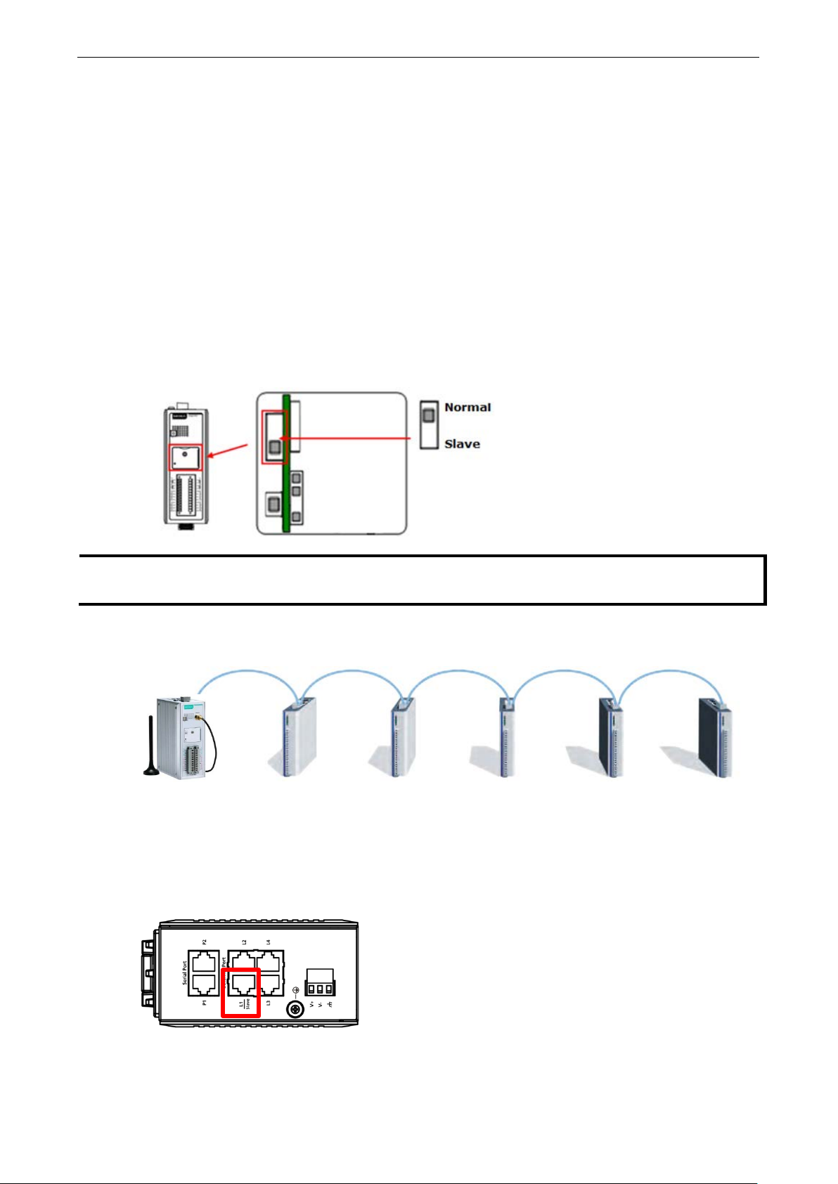
Daisy-Chaining for I/O Expansion
Up to 8 ioLogik E1200 devices can be connected in a daisy chain configuratio n to the ioLogik 2500 via the
L1/Slave port on the ioLogik 2500. An IOxpress configuration scheme is called a project. If the IOxpress
project includes expansion device s , the ioLog ik 2500 w ill a utomatic ally start running in expansion mode.
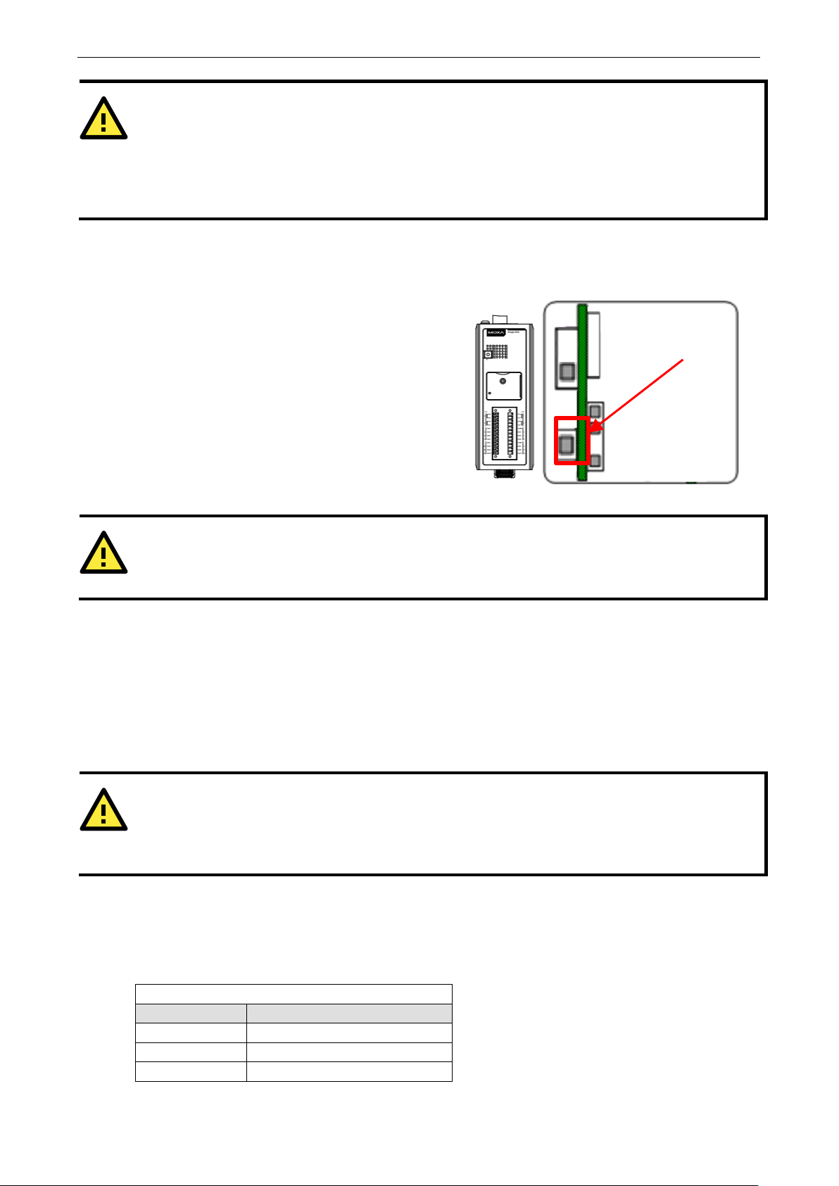
If the ioLogik 2500 is running, you can replace one of the expansion units w ithout powering down the
ioLogik 2500. Take the following steps to replace an expansio n unit:
1. Power-off the expansion unit.
2. Replace the unit with anothe r expansion unit of the same model.
3. Access the DIP switch bene a th the cover plate (a s shown below ).
4. Move the DIP switch from the down positio n to the up pos ition to tr igge r the ioLogik 2500 to refresh its
connection with the expansion units. If the DIP switch is already in the up position, move it down and
then back up again.
5. The expansion unit will sta r t running.
The following figure illustrates a s imple dais y -c hain of I/O modules using the ioL ogi k 2500 for w ire le s s
connectivity.
When daisy-chaining an array of devices, the first de v ice in the chain (after the ioLogik 2500) must be
connected to the L1 Slave port on the top of the ioLogik 2500 (outlined in red in the diagram).
When a network failure occurs between the ioLogik 2500 and expansion I/O units, the ioLogik 2500’s autorecovery mechanism will reestablish a connection onc e the network is back up and running.
f you would like to use a
Page 22
ioLogik 2500 Series Installation
2-8
ATTENTION
When using the ioLogik 2500 as the head of an array of ioLogik E1200 modules , make sure tha t:
If you need to reset the ioLogik 2500 to factory
defaults, press and hold the reset button (loc ate d
under the cover
more than
WARNING
Resetting your device to factory defaults w i ll res ult in the loss of all co nfig uration settings and any Click&Go
Plus logic settings that have
ATTENTION
The maximum cable length of a 10/100BaseT connection is 100 m (350 feet), but the a c tual limit co uld be
shorter depending on the amount of electr ic al nois e in the environment. To minimize the amount of noise,
Ethernet cables should not run parallel to power cable s or other cables tha t genera te el ectrical no is e .
1. You connec t the firs t E1200 expansion module in the array to the ioLogik 2500’s L1 Slave port.
2. A maximum of 8 ioLogik E1200 de v ices ar e connec te d in a single arra y.
3. You only use ioLogik E1200 devices in the array. Other devices cannot be used as part of the array.
Reset to Factory Defaults
-plate, as shown in the diagram) for
5 seconds.
Reset Button
Network Installation
Ethernet Communication
Connections to the LAN port are made through an RJ45 connector on the ioLog ik 2500 devic e . The wiring
and pin connections for these connectors ar e described in separate sections below.
TCP/IP Settings
The following table shows the TCP/IP parameter s suppor te d by the LAN por t. The io Log ik 2500 w ill reve rt to
these default values w he ne ver it is r ese t to factor y def a ults.
Parameter Supported Values
IP Address Defau lt: 192.168.127.253
Subnet Mask Default: 255.255.0.0
Gateway Default: 0.0.0.0
LAN Port
already been configured.
Page 23
ioLogik 2500 Series Installation
2-9
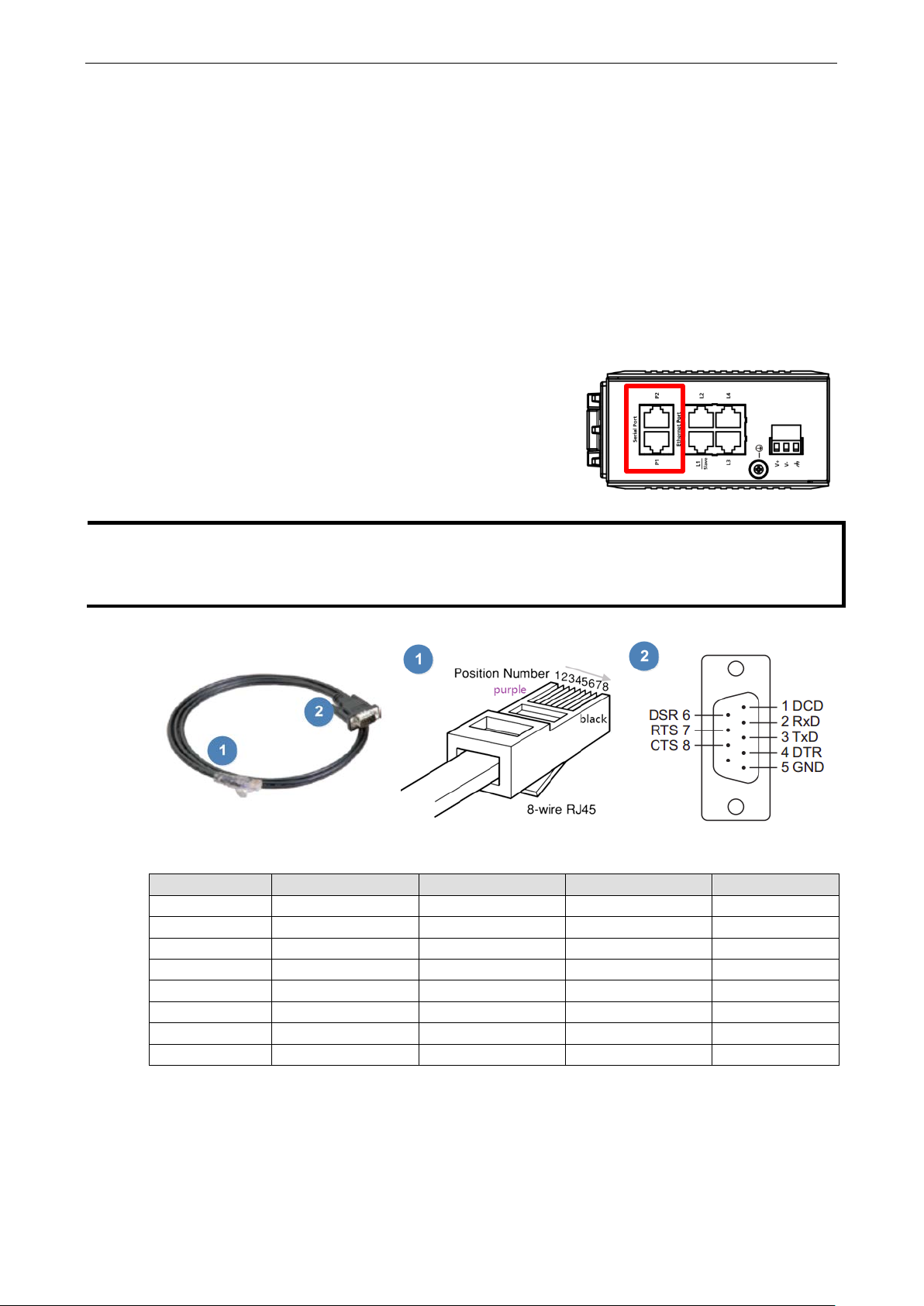
The ioLogik 2500 is equipped with two 3
selectable
RS
connect serial devices.
If required, the RJ45
used to connect to serial devices.
NOTE
The ioLogik 2500 is shipped with 2 RJ45 to DB9 connection cable s . If yo u need additional cables, contact
your Moxa sales representativ e.
The model name of the connection cable is
IP Address
The ioLogik 2500’s IP address.
Subnet Mask
Determines which subnet the device is connected to.
Gateway
The gateway IP address, which determines how the controller communicates with devices outs ide its subnet.
The IP address, subnet mask, and gateway are static; contact yo ur netw or k adminis trator to obtain these
addresses for the ioLogik 2500 device.
Serial Communication
-in-1 software-
-232/422/485 serial ports, making it more convenient to
to 8-pin male DB9 converter cab les can be
CBL-RJ45M9-150.
RJ45 to DB9 Conn ec ti o n Ca bl e RJ45 Connec t or Pinouts DB9M Connector Pinouts
DB9M Pin RS-232 RS-422 RS-485 RJ45 Pin
1 DCD RXD- DATA- 6
2 RXD RXD+ DATA+ 5
3 TXD TXD- – 4
4 DTR – – 8
5 GND GND GND 3
6 DSR – – 1
7 RTS TXD+ – 2
8 CTS – – 7
Page 24

ioLogik 2500 Series Installation
2-10
NOTE
Additional information on using IOXpr e ss c a n be found in
Software Installation—IOxpress Utility
The ioLogik 2500 can be remotely managed and configured ov er a n Etherne t with Moxa’ s IOxpress utility.
IOxpress is a Windows utility provided for the conf iguration and management of the ioLogik 2500. IOxpress
can be used to remotely monitor and configure devices from any location on the network. The IOxpress
graphical user interface provides e asy acc ess to all status info rmation and configuration settings, and can
also be used to configure Click&Go Plus rules and handle front-e nd eve nts .
System Requirements
Hardware Requirements
CPU Intel Pentium 4 CPU or higher
RAM Min. 512 MB, 1024 MB is recommended
Network Interface 10/100 Ethernet
Software Requirements
Operating System Microsoft Windows 2000, XP or later
Installing IOxpress
The software can be downloaded from Moxa’s website. To do this, first click on the following link to access
the website’s search utility:
http://www.moxa.com/support/search.aspx?type=soft
When the web page opens, enter the model name of your product in the search box. Click the model name
to navigate to the product page, and then click on Utilities (in the middle of the pag e ), loc ate d in the box
titled Software.
Download and unzip the file, and then run SETUP.EXE from that location.
The installation program will guide you through the installation process and install the softwar e . After the
installation is finished , run the softw are fro m the Window s Start m e nu.
Chapter 3: The IOxpress Utility.
Page 25

3
3. The IOxpress Utility
In this chapter, we introduce Moxa’s IOxpress Utility. The ioLogik 2500 can be managed and configured
over an Ethernet using the IOxpress graphical user inte r face, which provides easy access to all status
information and settings. IOxpress can also be used to configure Click&Go Plus rules to handle fr o nt-end
events.
The following topics are covered in this chapter:
Application Interface
Main Screen
Menu B a r
Using IOxpress
Configuration Flowchart
C o nfiguration Library
D e vice Library
Page 26
ioLogik 2500 Series The IOxpress Utility
3-2
NOTE
If the host computer has multiple interfaces , be sure to select the corr e c t network inte rface before searching
for online devices. If you select the incorrect inte rf a c e or do not enable an interface, the search action will
not find any devices. The interface settings c an be found in the menu bar Options
Application Interface
Main Screen
The following figure shows the main scree n of the IOxpress utili ty . The re are four main areas:
• Menu Bar
• Quick Launch Bar
• Configuration Console
• Log Messages
Menu Bar
There are five tabs on the menu bar:
• Project: For managing projects
• Device: For accessing functions to manage online devices
• Configuration: For performing configurations offline
• Options: Network interface and options
• Help: Version info rmation
Network Interfaces.
Page 27

ioLogik 2500 Series The IOxpress Utility
3-3
Using IOxpress
IOxpress sup po rts two configuration options: Config uratio n Libr ary and Device Library. Offline configuration
is usually completed first in the Config uration Library, and then the configurations are uplo ad ed over the
network to online devices.
Configuration Flowchart
The following flowchart gives an overview of the IOxpr e ss configuration process. Once offline config uration
is completed, you can start online configuration.
Configuration Library
1. Select Device Confi guration
Template
2500 + E1200
2. Detailed configuration
general settings
Click&Go Plus logic
Peer to Peer
Configuration Library
The operator uses IOxpress to store configuration options offline in IOxpress Projects. The configuration
settings are stored on the user’s computer.
See Chapter 4 for a detailed explanation.
Device Library
Device Library
1. Auto-search for online
devices
2500 + E1200
2. Select the functions to be
executed, and then
configure them
3. Deploy the configuration to
one or more devices
The operator uses IOxpress to export the configuration to devices on the network. That is, settings that
were configured offline are exported over the network to online de v ices . This can be done either in batch
mode, or on a case-by-case basis.
IOxpress can also be used to access online devices directly to check I/O status, upgra d e firm w are , expo r t
configurations, and restart devic e s.
See Chapter 5 for a detailed explanation.
Page 28

4
4. Configuration Library
With Configuration Library, the operator uses IOxpress to store configuration options offline in IOxpress
Projects. The configuration settings are stored on the user’s computer.
The following topics are covered in this chapter:
Introduction
Saving Configurations as a Project
A d ding an ioLogik 2500 Device to a Project
A d ding E1200 I/O Expansion Modules to a Project
Duplicate Device Configuration for Mass Deployment
Setting Up a Device
Settings Tab
System
Security
Network
I/O
AOPC
SNMP
Modbus/TCP Slave
Mo d bus/TCP Master
S e r i al Por t (Port1/Port2)
D ata Log g ing
C lic k&Go Plus
Click&Go Plus Tab
Click&Go Plus Simulator Tab
Peer-to-Peer Tab
General Settings
Peer-to-Peer Rule Settings
Page 29
ioLogik 2500 Series Configuration Library
4-2
Introduction
With Configuration Library, the operator uses IOxpress to store configuration options offline in IOxpress
Projects. The configuration settings are stored on the user’s computer.
Saving Configurations as a Project
IOxpress configuration schem es a re cal led Projects (saved as *.prj files).
The first step to using IOxpress is to create a project for automating yo ur d evic e conf iguration processes.
This can be done offline, after which the project ca n be expor ted to o ther devic e s over the netwo rk dur ing
the online configuration phase (discussed in Chapter 5: Device Library).
Projects are automatically saved in the following folder:
C:\Users\Public\Documents\Moxa\IOxpress\Database
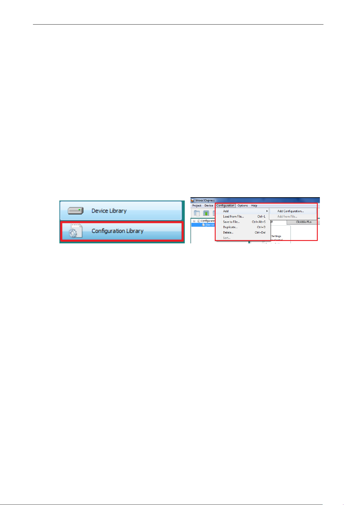
The first time you use offline configuratio n, create a new projec t by clicking New from the dropdown menu
under the Project tab.
Click Configuration Library and then select Configuration fro m the toolb ar. You may click on either
Add Configuration… or Load from File… to add a config uration to the new project.
Add
Adding an ioLogik 2500 Device to a Project
The ioLogik 2500 can be used as the head of a cascaded array of ioLogik E1200 modules , with C lic k &G o
Plus logic used to extend communication capability to the all of the expansion units.
Page 30
ioLogik 2500 Series Configuration Library
4-3
ioL
ATTENTION
If the IOxpress project includes expans ion devices, the
mode.
ATTENTION
The IP address of the ioLogik 2500 should not be the same as its E1200 expansion units.
NOTE
The following ioLogik E1200 models can be used for ioLog ik 2500 I/O arr ays:
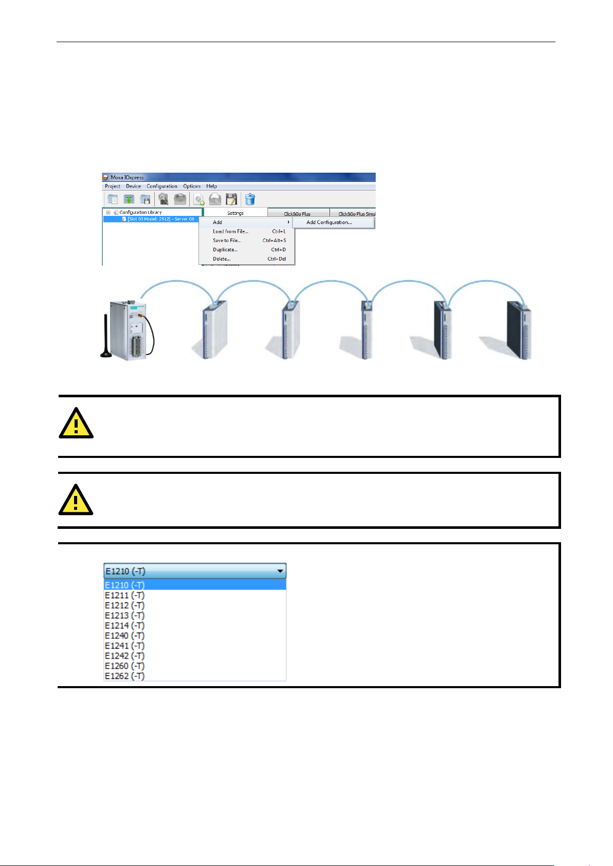
Adding E1200 I/O Expansion Modules to a Project
Up to 8 ioLogik E1200 series devices can be connected to the ioLogik 2500 in a daisy -chain co nfiguration.
Right click on the ioLogik 2500 device you have just added, and then sele c t Add Add Configuration….
After adding an E1200, the settings for the added dev ice c an be found in the I/O settings, Tag selection,
and data logging – profile areas. The expansion status (0: disconnect; 1: Good) can be monitored via
Modbus, AOPC tag, SNMP, and RESTful API.
ogik 2500 ioLogik E1200 ioLogik E1200 ioLogik E1200 ioLogik E1200 ioLogik E1200
L1/slave port will automatically run in expans io n
Page 31
ioLogik 2500 Series Configuration Library
4-4
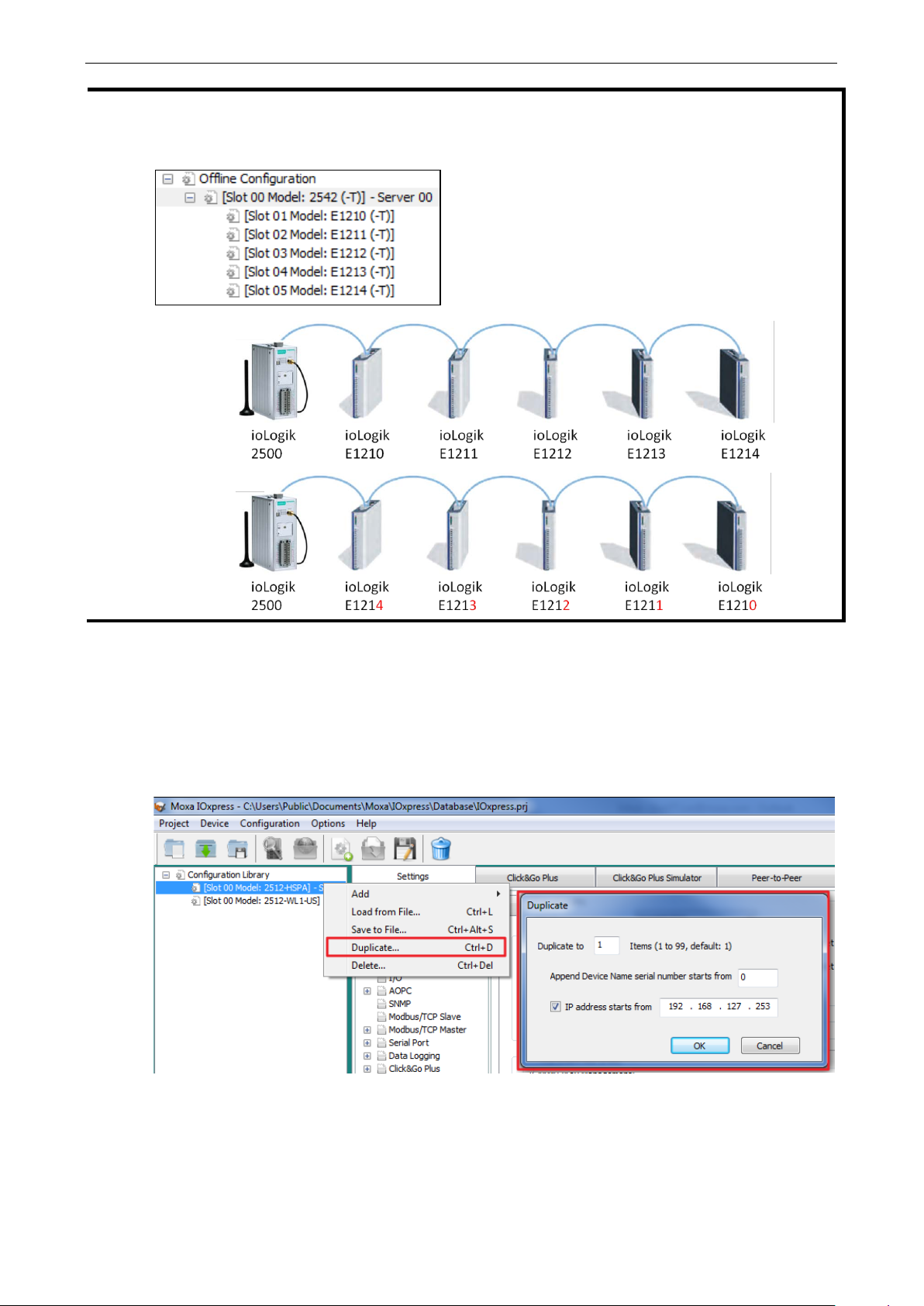
NOTE
The
If you would like to change a device in an E1200 array, make sure that the
order of the expansion modules is the same as in the Expansion Config uration list you just modified. An
example is shown below:
order of each model is fixed.
x
Duplicate Device Configuration for Mass Deployment
Use the Duplicate… function to quickly duplicate a configuration. First use Duplicate is to save your first
configuration as a template, and then use the duplicate function to duplicate the configuration template to
devices that have a different name, serial number, and IP address.
To do this, right click on a co nfig uration template and select Duplicate… from the dropdown list.
Page 32
ioLogik 2500 Series Configuration Library
4-5
Click
Device Name
During
will
During online configuration, the device name will
appear in the
supports long
up to 30 characters.
Time Settings
The
the time server
box.
the
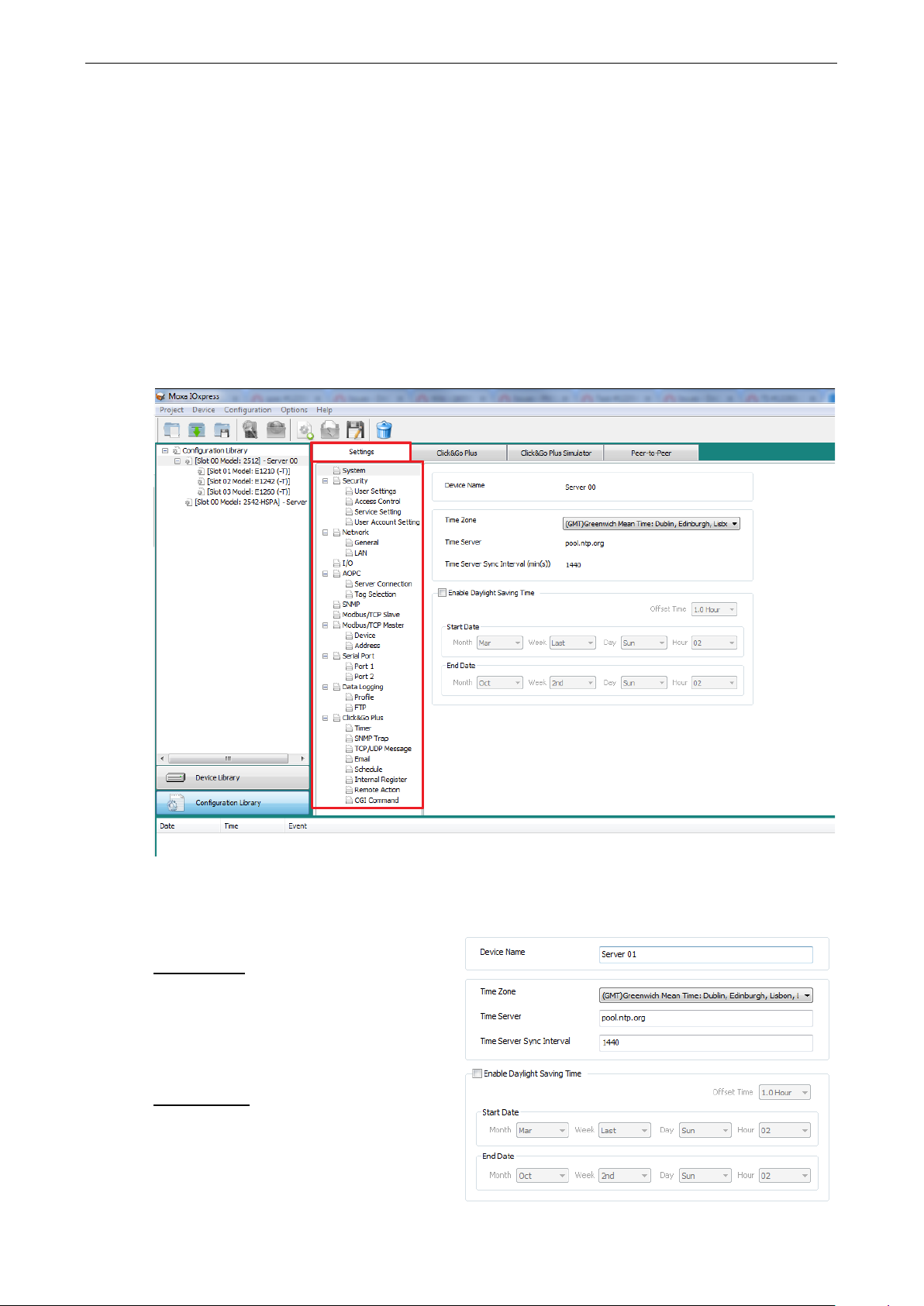
Setting Up a Device
After you have created the project, you can start to config ure each devic e in the pro ject. The configuration
window has four tabs:
• Settings
• Click&Go Plus
• Click&Go Plus Simulator
• Peer-to-Peer
Settings Tab
The Settings panel includes basic settings used to set up devices.
System
System to configure the fo llo wing items:
offline configuration, the device name
appear in the list of ioLogik 2500 units.
iologik 2500 will synchronize its time with
During online configuration, you can sync
PC’s time with the ioLogik 2500’s time.
mass deployment list. IOxpress
device names
indicated in the Time Server
Page 33

ioLogik 2500 Series Configuration Library
4-6
Daylight Saving Time
Select the
configure the
NOTE
Since the configuration is being done off line , the resul ts ar e stor ed in your compute r, and not in the ioLogik
device. Therefore, when updating this configuration to the ioLogik device, you will need to log
previous password.
Enable Daylight S avi ng Time c he ckbo x if your reg ion s upp or ts daylight saving time, and then
Offset Time, Start Date, and End Date.
Security
Configure the security settings to inc rease the security level of the device. Be sure to change the default
username/password the first time you configure this device, and then change it regularly thereaf ter .
User Settings
Each ioLogik 2500 is limited to precisely thre e users . Only the Username and Password of each user can
be modified. The No., Type, and Permission Level items cannot be changed. Use the Enable check box
(default: disable) to enable/disable Operator and User.
The factory defaults and access rights of the three user types are described below:
User Type Factory Default Access Right
Administrator admin Full control, including the ability to configure the device
Operator operator Can control I/O status through the web console
User user Can check I/O status through the web console
The characteristics of the username and password are described below:
Username:
Length: 1 to 30 characters
Acceptable characters: A to Z, a to z, 0 to 9, symbols; spaces are not allowed
Factory defaults: (see table above)
Password:
Length: 4 to 16 characters
Acceptable characters: A to Z, a to z, 0 to 9, Symbols, at least one number and one symbol
Factory default: moxa
in with the
Page 34

ioLogik 2500 Series Configuration Library
4-7
ATTENTION
To guard against cyber attacks,
when updating the password. Be sure to change the default password of each username before you start
using your ioLogik devices, and then change the passwo rd s at regular intervals.
NOTE
If all services are disabled, this device will no longe r be access ib le , and you will ne e d to load the fac tor y
default configuration to access the dev ice.
NOTE
MX
the password fields require at least one number and one symbol
Service Setting
Configure the service settings to enable/disable different services to prevent unintend e d acce s s . The
Default Configuration enables Web Server, Auto Search, and IOxpress Service. Enable other services (e.g.,
Modbus/TCP Slave) if additional serv ic e s are required.
-AOPC UA Serve r Service runs through the PC’s AOPC d ata co mmuni c ation ports 9500/9900.
User Account Settings
The user account settings include the following parameters.
• Idle Timeout: The system will log out idled users automatically when the idle timeo ut period is
surpassed.
• Retry Failure Threshold: Users will be locked out after this many unsuccessf ul log ins .
Page 35

ioLogik 2500 Series Configuration Library
4-8
• Lockout Time: The system will be locked for this period of time when the retry failure threshold is
surpassed.
• Login Failure Message: The system message that pops up when after an unsuccessful login.
• System Use Notification: The syste m messag e that wil l be displayed on the login page located below the
username and password field.
Access Control
Use IP Address / Netmask combinations to control which dev ic e s can use the Modbus/TCP protocol to
access your ioLogik device.
Network
There are three sub-pages under Network: General, LAN, Cellular (applies to the ioLogik 2500-
GPRS/HSPA only), and Wi-Fi (applies to the ioLogik 2500-WL1 only).
General
There are two columns under General: Select Network Interface and General Settings.
Select Network Interface
Select Network Interface is only available for the io Log ik 250 0 -GPRS/HSPA models. See Chapter 4:
Cellular Network Setup and Confi gura tio n for details.
General Settings
Page 36

ioLogik 2500 Series Configuration Library
4-9
An array of up to 8 modules can be connected to the
ioLogik 2500.
assigns an IP to the first E1200
subsequent
assigned consecutively. For example, if the IP of the first
E1200 device is set to 192.168.120.1, the IP of the second
E1200 will be 192.
192.168.120.3, and so on.
You can set up a static or dynamic IP address
for the ioLogik, as well as the subnet mask
and gateway address.
Use this field to specify the IP addresses of
one or two DNS servers. DNS servers ca n be
used to find available e-mail addresses when
setting up Click&Go
NOTE
The
Enable Web Console
Use this checkbox to enable or disable the web console. When enabled, the ioLogik can be configured from
a web browser. If not enabled, you will not be able to open the web console.
Enable Server Socket Idle Connection Timeout
Server Sock e t Id le Connect io n T imeout is designed to avoid TCP connection failures when the network
host is unable to respond due to a hardware failure or network prob le m.
If Server Socke t Idle Connection Timeout is enabled: When the server’s connection to the ioLogik 2500
exceeds the specified time period the device will auto m atic a lly re le as e its TCP connection to the server to
free up the port for the next connection.
If Server Socke t Idle Connection Timeout is not enabled: If the network host is unable to respond due
to a hardware failure or network problem, the ioLogik will continue to wait for a response from the host,
causing the TCP port to be occupied indefinitely by the host.
Private IP for the First Expansion Module
Private IP for First Expansion Module
module. The IPs for
modules in the chain will be automatically
LAN
168.120.2, the third IP will be
IP Settings
Plus rules.
Cellular (ioLogik 2500-GPRS/HSPA only)
ioLogik 2500-WL1 o nly supp or ts static I P addresses.
Cellular is only available for the ioLogik 2500-GPRS/HSPA models. See Chapter 4: Cellular Network
Setup and Configura tion for details.
Page 37

ioLogik 2500 Series Configuration Library
4-10
Channel No.
Sampling Time (min)
Wi-Fi (ioLogik 2500-WL1 Only)
Wi-Fi is only available for the ioLogik 2500-WL1 models. See Chapter 5: Wireless LAN Network S etup
and Configuration for details.
I/O
In the I/O section, you can configure I/O settings for ioLogik 2500 devices. Items that can be modified will
be shown in black. Items that cannot be modified will be shown in light gray. Because revising channel
type and name also changes each I/O setting, we recommend configuring the I/O Mode Settings first.
Setting Functions
IO Mode Setting Channel Mode
Name
DI Setting Filter
Counter Setting Filter
Initial Value
Trigger Mode
Power Off Storage
Power On Value
Power On Status
DO Setting Enab l e Com munic a tio n Wa tc hdo g for Safe Mode
Enable Auto Clear Safe Mode
Pulse Setting On Wid th
Off Width
Count
AI Setting Cha nne l Mo d e
Burnout Value
Scaling Slope
Virtual Channel Setting Enable
Slot No.
Scaling Enable
Scaling Slope
Scaling Offset
Scaling Interval
Power On Status
Power On Delay
Safe Mode Status
Power On Status
Power On Delay
Safe Mode Status
Scaling Offset
Scaling Unit
Function
Interval (min)
Page 38

ioLogik 2500 Series Configuration Library
4-11
NOTE
Since the ioLogik 2500 does not have AO
contains E1200 AO modules, such as the E1241.
Select Module
Select the module that you would like to configure. Yo u may select All modules, in which case information
on all I/O channels in the project will be displayed .
IO Mode Setti n g
• Channel Mode
DIO channels can be set to one of four modes: DI, Event Counter , DO, or Pulse output. AI channels
can be set to one of five modes: ±10 V, 0 to 10 V, 0 to 20 mA, 4 to 20 mA, or 4 to 20 mA
(Burnout). AO channels can be set to one of two modes: 0 to 10 V and 4 to 20 mA.
• Name
The name will be attached to the AOPC tag to help users identify c hanne l infor m atio n in MX-AOPC.
DI Setting
Filter: Software filtering is used to avoid switch bounces. The filter is configurable in multiples of 100 μs
and accepts values between 1 and 65535.
channels, the AO setting will only show up when the project
Counter Setting
Counter refer s to an Event Counter channel. Co unts are stored inte rnally.
• Filter
Software filtering is used to avoid switch bounces. The filter is configurable in multiples of 100 μs and
accepts values between 1 and 65535.
• Initial Value
The initial value is the start value in counter mode.
Page 39
ioLogik 2500 Series Configuration Library
4-12
• Trigger Mode
In Trigger mode, the channel accepts limit or proximity switches and counts events according to the
ON/OFF status. When Rising edge is selected , the counte r value inc reases when the attached switch is
pushed. When Falling edge is selected, the counter value increases when the switch is released. When
Both is selected, the counter value increases when the attache d swi tc h is pus hed or rele ased .
• Power On Status
To enable the counter to resume counting immediate ly upon powering up, enable the Power On Status.
Stop: The counter star ts logging s i g nals o nly af ter config ured to do so by a Modbus or a Click&Go Plus
command.
Start: Counting begins automatically whenever the io Log ik is power ed on.
• Scaling Enable / Scaling Slope / Scaling Offset / Scaling Interval (sec)
Set the Slope & Offset to convert the Counter value to a new value. The scaled value = (original v alue
* Scaling Slope) + Scaling Offs e t.
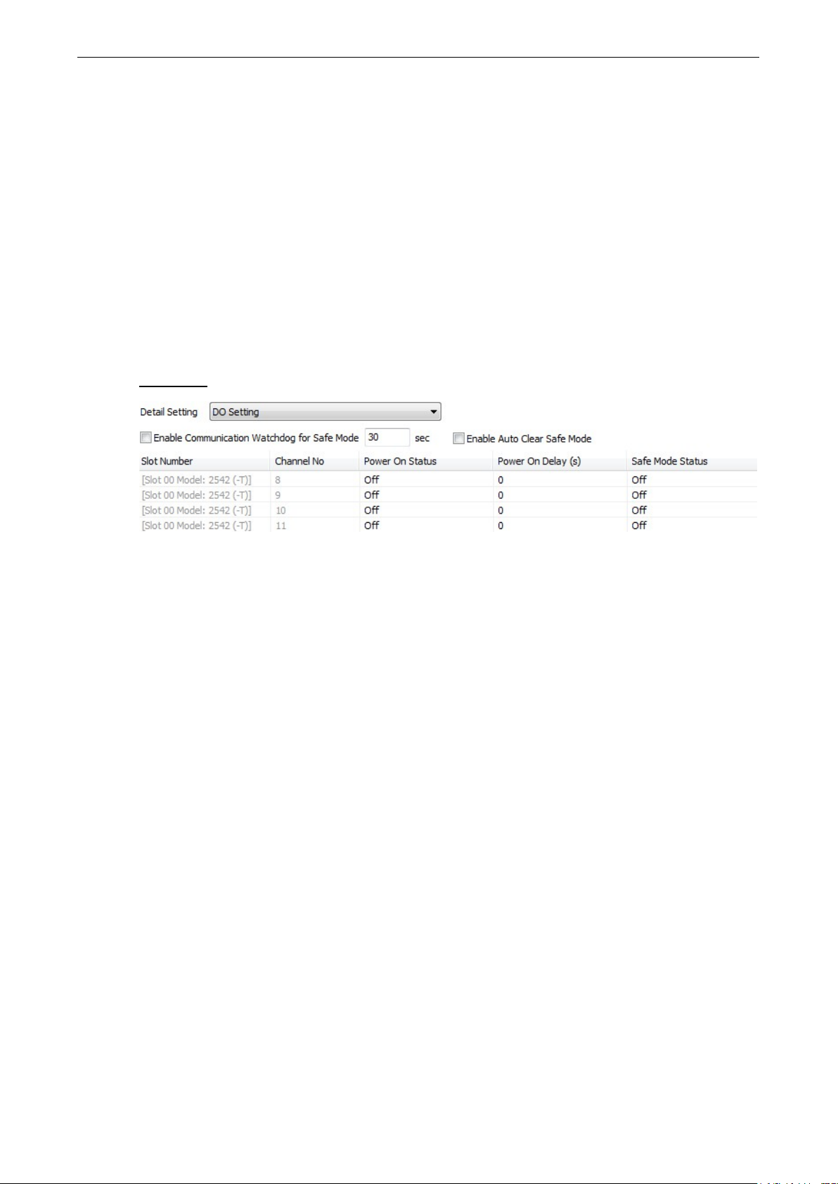
DO Setting
• Enable Communication Wa tchd og for Saf e Mo de
When the watchdog is enabled, any disconnection from the network will activate a safe state. In the
safe mode, DO channels can be configured to turn on, turn off, or commence puls e output d uring the
safe state. If the watchdog is not enabled, then DO channel sta tus w ill rem ain unc ha ng ed dur ing a
network disconnection.
To configure a DO for s afe mode , set the corresponding value in the Safe Mode Status column to ON.
• Enable Auto Clear Saf e Mo de
When detecting the reconnection of Ether net sig nal s , the devic e will auto c le ar the safe mode status.
• Power On Status
When the device is powered on, the status of each DO channel is set to OFF by default. This status can
be modified to ON.
• Power On Del a y
The time delay from tuning DO channels when the power is turned on.
• Safe Mode Status
Enable Communication Watchdog for Safe Mode allows you to control how DO and pulse output
channels act when the network is disconnected .
If the Communication Watchdog is enabled, a network disconnection will activate a safe state. The DO
channel can be configured to turn on / turn off during the safe state.
If the Communication Watchdog is not enabled, then the DO c hanne l status w ill rema in unchange d
during a network disconnection.
Page 40

ioLogik 2500 Series Configuration Library
4-13
Pulse Setting
• On Width / Off Width
In Pulse Output mode, the selec te d digital output channel will generate a square wave as specified in
the pulse mode parameters. The low and high level widths are specified in multiples of 100 μs, with a
maximum setting of 65,535.
• Count
You can specify between 1 and 4,294,967,295 pulses or enter “0” for continuous pulse output.
• Power On Status
When the device is first powered on, the status of each pulse o utp ut channel is set to OFF by default.
You can set a pulse output channel to turn ON when the ioLogik is powered on, or to commence pulse
output.
• Power On Del a y
The time delay from tuning Pulse channels when the pow er is tur ne d on.
• Safe Mode Status
If the Communication Watchdog is enabled, a network disconnection will activate a safe state. The pulse
output channel can be configured to turn on / turn off during the saf e state .
AI Setting
• Channel Mode
The input channels can be set individually to±10 V , 0 to 10 V, 0 to 20 mA, 4 to 20 mA, and 4 to 20 mA
(Burnout).
Page 41
ioLogik 2500 Series Configuration Library
4-14
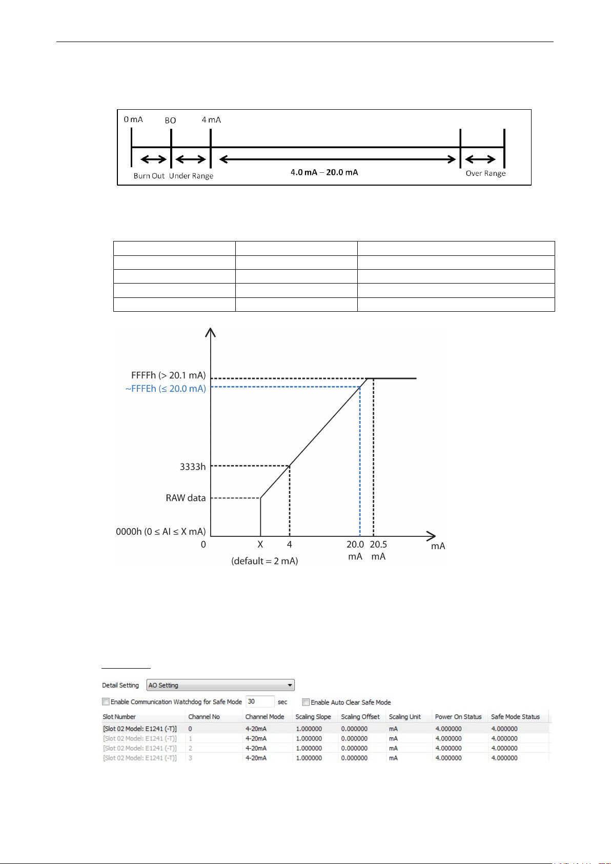
• Burn-out Value
Burn Out mode indicates when the Current AI has burned out. For example , the 4–20 mA Burn-out
mode is defined in the following diagram:
Users can define Burn-out (BO) values (default = 2 mA) for selected ranges. When input values are in
the Burn Out range, raw data will register as 0000h to indicate that the analo g input has burned out.
The definition of raw data is as follows:
Burnout Value (BO) 0.0 < BO < 4.0 User defined (d ef ault 2 mA)
Burnout State 0 ≤ AI < BO mA Modbus output 0000h
Under Range BO ≤ AI < 4 mA Modbus output raw data
Normal Range 4 ≤AI ≤ 20.00 mA Modbus output raw data until FFFEh
Over Range XX > 20.00 mA Modbus output FFFFh
• Scaling Slope / Scali ng Of fse t /Sc aling Unit
Enabling the Scaling functions will line arly convert the actual current or voltage value into other userdefined units, such as percentage or ppm (parts per million).
Set the Slope & Offset to convert the AI value to a new value. The s c aled value = (or iginal v alue *
Scaling Slope) + Scaling Offset.
AO Setting
• Channel Mode
There are two modes for the AO channels: Voltage Mode (V) and Current Mode (mA).
Page 42
ioLogik 2500 Series Configuration Library
4-15
NOTE
Since the ioLogik 2500 does not have AO channels, the AO setting will o nly show up when the projec t
contains E1200 AO modules (such as the E1241).
• Scaling Slope / Scali ng Of fse t / Scal ing Unit
Enabling the Scaling functions will line arly convert the actual current or voltage value into other userdefined units, such as percentage or ppm (parts per million).
Set the Slope & Offset to convert the AO value to a new value. The scaled value = (original v a lue *
Scaling Slope) + Scaling Offset.
• Power On Status
When the device is first powered on, the status of each AO channel can be modif ied us ing the Power
On Status.
• Safe Mode Status
Enable Communication Wa tchd og for Saf e Mo de allows you to control how an AO channel acts
when the network is disconnected.
If the Communication Watchdog is enabled, a network disconnection will activate a safe state. The AO
channel can be configured to a defined value during the safe state .
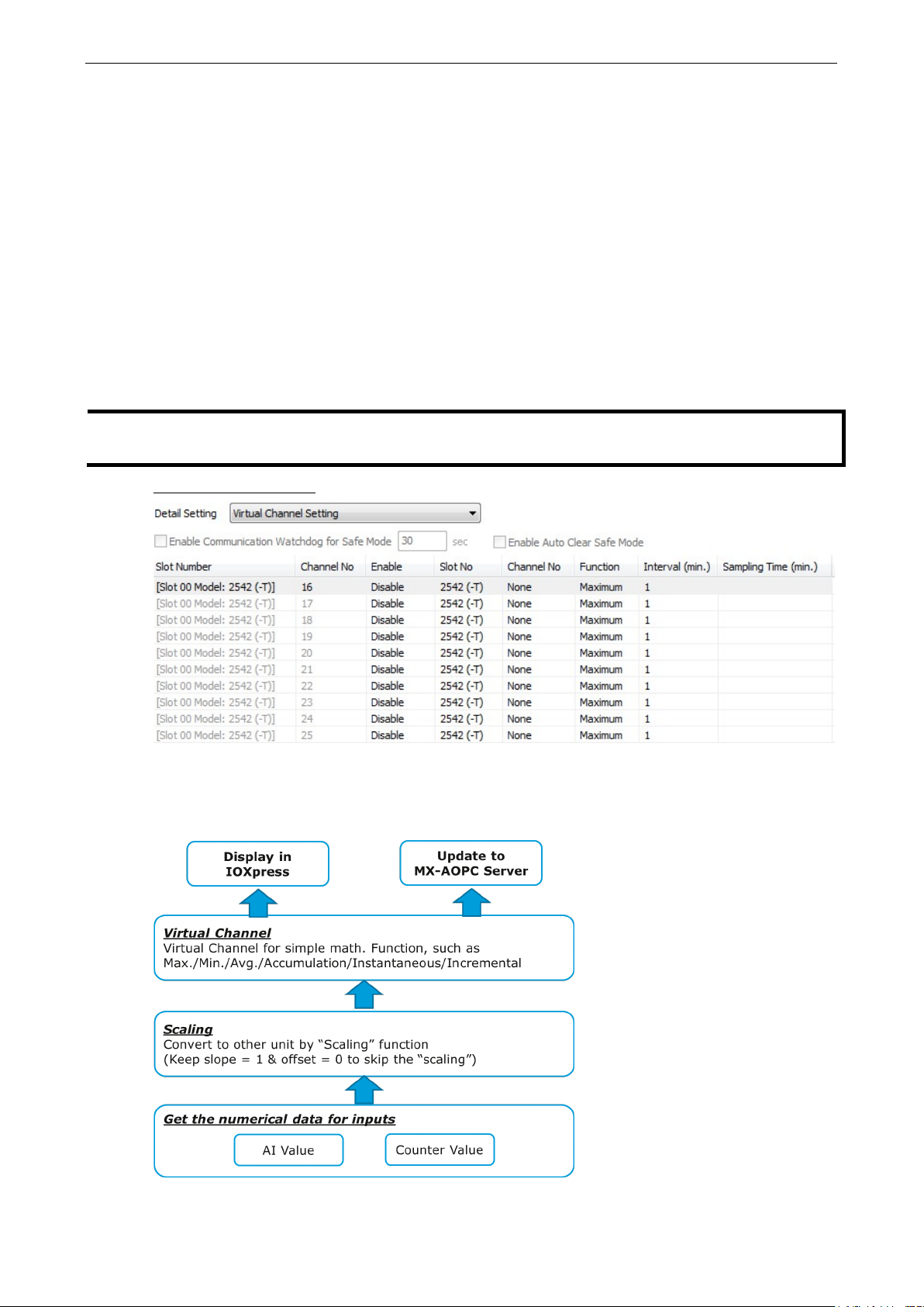
Virtual Channel Setting
The ioLogik 2500 has 10 internal virtual channels to s uppor t fro nt-end sta tis tic s functions.
The data source is the real I/O channel, such as AI and DI counters, some of whic h need to be converte d to
the appropriate time unit. The operation is illustrated below.
Page 43
ioLogik 2500 Series Configuration Library
4-16
NOTE
For AI/Counter scal
operations in the virtual channels.
If you have connected E1200 expansion modules, selec t the dev ic e you
would like to configure here.
For example, if you want to monitor the daily flow at a point in a pipeline, you can use a pulse output flo w
meter, where 1 pulse indicates 5 ml. You can set the virtual channel’s scaling function so that 1 tick of
counter input equals 5 ml. Next, set the Accumulation flag, and configure the Time Interval to 24 hours.
This will set up the virtual channel to log the total water flow vo lum e ove r a p er i od of 24 hours.
• Status
Enable/Disable virtual channels.
• Slot No.
• Channel No.
Virtual channels are required to config ure AI or counter c hannels.
• Function
There are six functions: Max, Min, Average, Acc um ulation, Instantaneous, and Incremental.
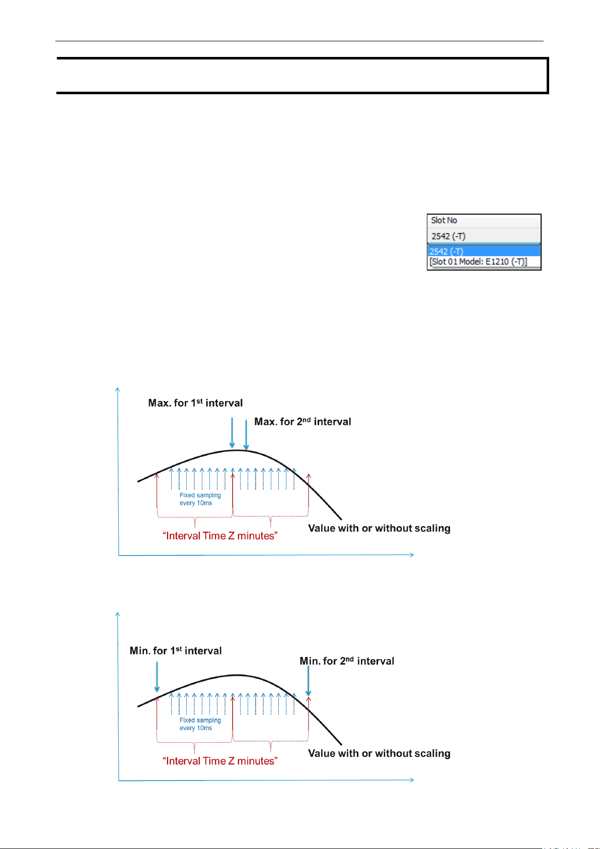
Maximum:
The maximum value within Z sec, with sampling done every 10 ms.
ing, configure Scaling on the AI or Counter Configuration panel before selecting
Minimum:
The minimum value within Z sec, with sampling done every 10 ms.
Page 44

ioLogik 2500 Series Configuration Library
4-17
Average:
The average value within Z sec, with sampling done every 10 ms.
Instantaneous:
The instantaneous value when a sample is taken.
Incremental:
The difference (Δ) between two samples.
Page 45
ioLogik 2500 Series Configuration Library
4-18
Accumulation:
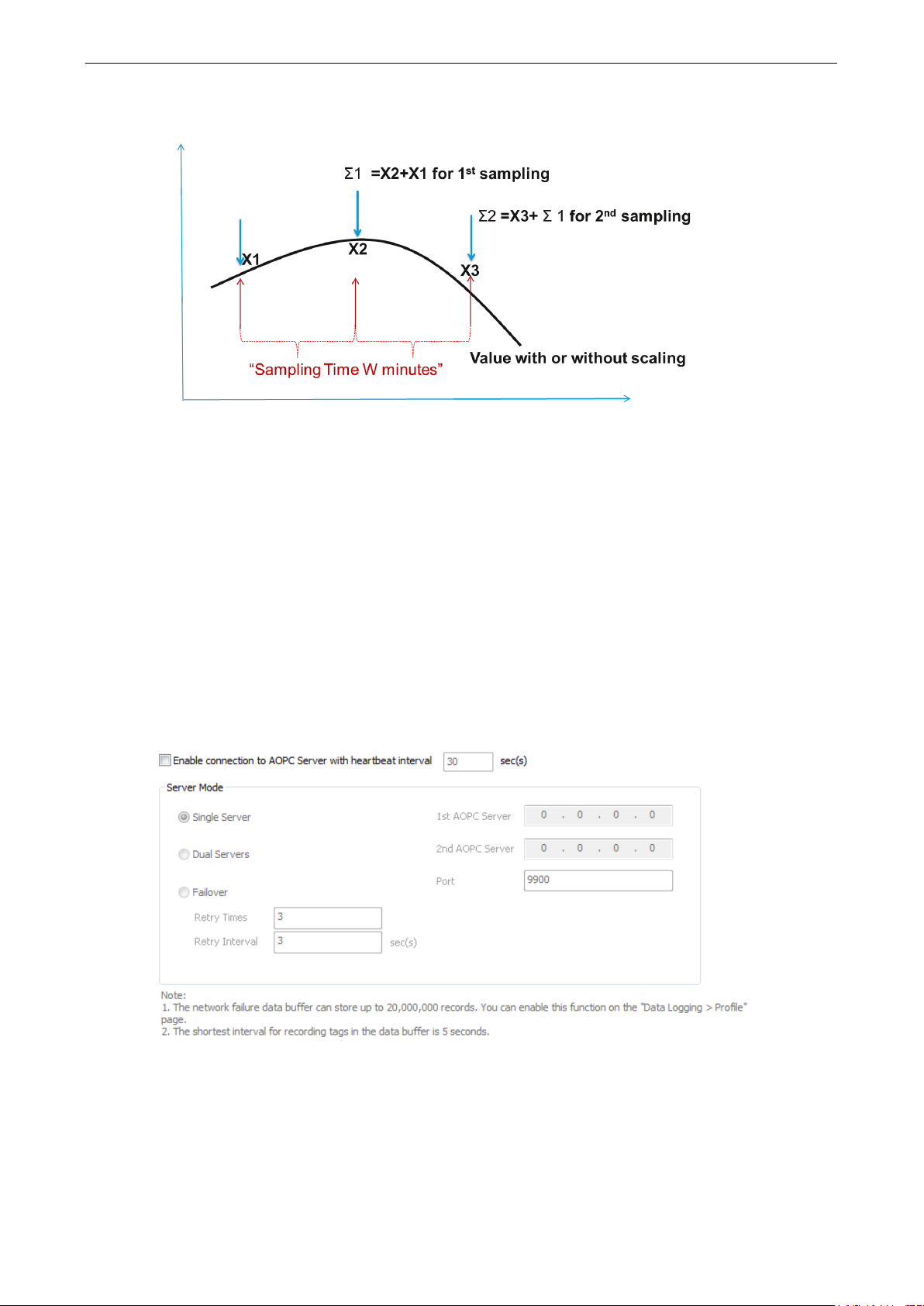
The sum (Σ) of all sampling values.
• Interval (min.)
Set the interval time (Minutes) for Maximum, Minimum, and Average functions.
• Sampling Time (min.)
Set the sampling time (Minutes) for Instantaneo us and Incrementa l f unc ti o ns .
AOPC
Moxa MX-AOPC Server is a software package operated as an OPC driver of an HMI or SCADA syste m . I t
offers seamless connection from Moxa ioLogik series products to SCADA systems.
Server Connection
You can set the ioLogik 2500 to connect to MX-AOPC UA Server. Each ioLogik 2500 ser ie s can co nnect to
two MX-AOPC UA serv ers. You can also set different modes to send active tags.
Enable connection to AOPC Server with heartbeat interval
The Heartbeat Interval can be used to determine the connection status between the ioLogik 2500 and
MX-AOPC Server, and to ensure that the ioLogik 2500 is connected and aliv e . If the heartbeat inte rval is set
and the network between the ioLogik 2500 and MX-AOPC Server is down, MX-AOPC Server will detect the
stopped heartbeat and the Quality column in the MX-AOPC Server will d is play BAD to indicate the loss of
connectivity.
Page 46
ioLogik 2500 Series Configuration Library
4-19
Server Mode
The ioLogik 2500 can send active tags to one or two MX-AOPC UA servers. You ma y choose one of three
server modes.
1st AOPC Server
IP address of the 1st AOPC server.
2nd AOPC Server
IP address of the 2nd A OP C server.
Single Ser ver
The ioLogik 2500’s active tags will be sent to a single AOPC serv e r.
Dual Servers
The ioLogik 2500’s active tags will be sent to two AOPC server s .
Fail Over
The ioLogik 2500 will try to connect with the first MX-AOPC Server IP. If it cannot connect, it will
automatically connect with the seco nd IP, and w he n the connection to the second IP fails, it will switch back
to the first IP.
Data buffer for network failure
The ioLogik 2500 supports a data buffer function that stores transmitted data on an inserted SD card when
the connection between MX-AOPC UA Server and the ioLogik 2500 was down. MX-AOPC UA Logger will
automatically retrieve the buffering data after the connection b e twee n MX -AOPC UA Server and the ioLog ik
2500 is back up and running. The network data buffer can store up to 20,000,000 records. Enable this
function under Data Logging Profile. For details, see the “Data Logging” se c tion of this document; the
shortest interval for recording tag s is 5 second s . Refer to the MX-AOPC UA Server and Logg er user’s
manuals for details.
Tag Selection
Use tag selection to select which active tags will be updated to MX-AOPC UA server.
Select Module
Use the select module function to check the ioLogik 2500 and its IO expansion modules. If you select All,
all modules will be selected.
Page 47
ioLogik 2500 Series Configuration Library
4-20
NOTE
A s
fee
loading and unstable performance.
I/O Type
Select the type of data you would like to record. Choose from DI, Counter, DO, Pulse, AI, Internal Register,
Virtual Channel, Serial Tag, and RSSI (cellular models only).
Select All/Unselect All
You may select all c hanne ls , or deselect all channels.
Apply to All
You can apply one parameter to all channels. For example, if yo u can change On Change from disabled to
enabled and then click Apply to All, all AI channels will be enabled.
Update Method
• On Change for DI/DO/Pulse/System Tags: The ioLogik will update the tag value to MX-AOPC UA
Server whenever the tag status changes.
• On Change for AI Tag: If the AI is configured to update on change, the percentage setting s re pr e s e nt
the percentage of the full analog range. For example, if the AI is configured to 0 to 10 V, “On Change
1%” means the ioLogik will update to the MX-AOPC Server every time there is 0.1 V change.
• Interval for Counter/AI/ RTD/TC/IR/FIR/VC/Ser i al Tag s : The ioLogik will update the tag value to
MX-AOPC UA Server when the interval time elapses. The interval time can be configured to between 1
and 65535 seconds; the default is 5 seconds.
SNMP
horter interval time may cause a large number of data packets to be generated, resulting in higher data
if you are using a pay-by-packet connection plan. The ioLogik might also experience higher system
The ioLogik supports SNMP (Simple Network Management Protocol) v1, v2c, and v3 to monitor network and
I/O devices with SNMP Network Management softw are. I t is use f ul in build ing automation and telecom
applications. Use these fields to e nable SNMP and se t the read and write co mmuni ty strings for SNMPv1 and
SNMPv2c, or use authentication for SNMPv3.
Page 48
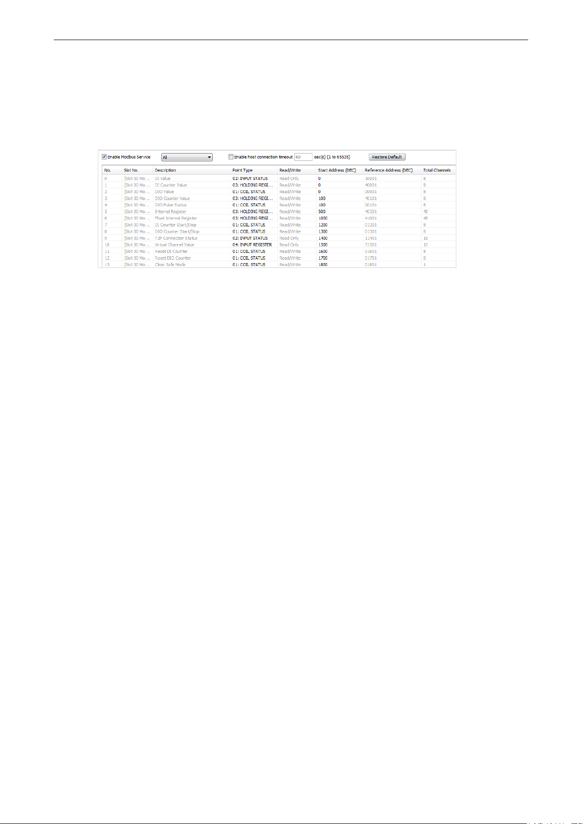
ioLogik 2500 Series Configuration Library
4-21
Modbus/TCP Slave
In this section, I/O addresses can be config ured for dif fe r e nt for m ats . Select the Enable Modbus Service
checkbox to enable the Modbus/TCP Slave function of the devi c e . The device supports user-defined Modbus
addresses for mapping Modbus data to existing upper level programs; update the start address of each
item and to map data to the conf igured address.
Enable Modbus Service
Enable/Disable the Modbus service setting to turn the Modbus/TCP slave protocol on or off.
Enable host connection timeout
Enable the host connection timeout setting to monitor the Modbus connection status between the Modbus
Master and the ioLogik 2500 M odbu s service. The connection status can be a condition of a Click&Go Plus
rule.
Restore Default
Click the Restore Default button to restore default settings of the Modb us servic e .
Page 49

ioLogik 2500 Series Configuration Library
4-22
Modbus/TCP Master
The ioLogik 2500 supports a Modbus/TC P Master function that acts as a Modbus/TCP master for monitoring
the data from two connected Modbus/TCP slave devices . The collected data can be used by Click &Go Plus or
in an upper level system after the data is transmitted via a Modbus, AOPC, SNMP, or RESTful API
connection. The data can also be recorded locally using the Data Logging function.
Device
Configure the connected Modbus/TCP sla v e dev ic e se tting s .
• Enable Data Collection: Check to enable Modbus data collection
• Device Name: Name the slave device (e.g., F lo w Meter )
• IP Address: Fill in the IP address of the slave device
• Port: Fill in the Modbus communication port of the slave devic e (def a ult: 502)
• Delay between polls: Set the delay time between polls (default: 502)
Click the Advanced button to display the advanced fields for timeout/retry settings. Refer to the
connection cycle diagram below for details.
• Connection Timeouts: Modbus initial connec tion timeout
• Reconnect Delay: Delay time between timeout and start s lave devic e reco nne c tio n
• Reconnect Cycles: Set reconnect times for e ac h slav e device re c o nnection cycle
• Cycle Delay: Delay time between each reconnectio n cy c le
• Polling Timeouts: Set timeout to trigger a polling retry for polling co mmand
Page 50
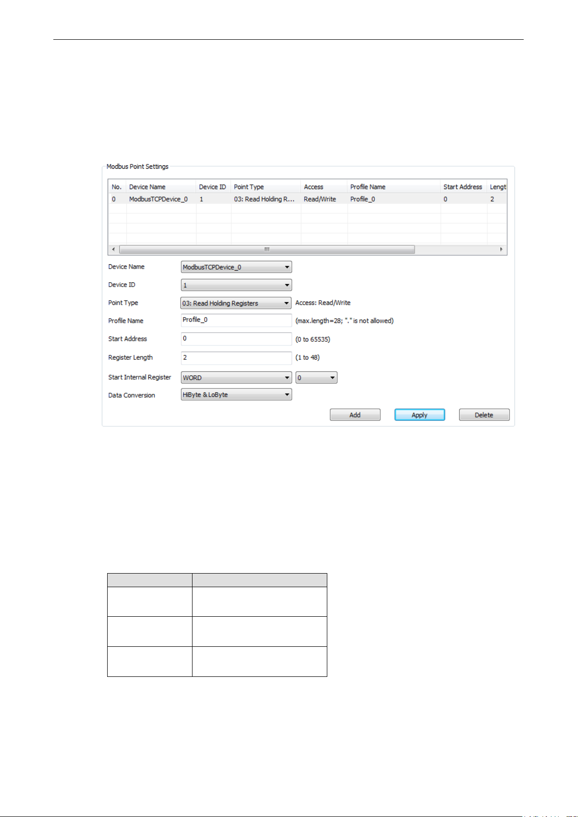
ioLogik 2500 Series Configuration Library
4-23
• Polling Retries: The number of polling retry times for the polling command before proceeding with
reconnection
Address
Configure the address settings for monitoring the Mod b us /TCP s lave dev ice co nf igur ed in the previous
paragraph.
• Device Name: Select which devices will be configured under Modbus/TCP Master Device
• Device ID: Set target slave device ID
• Point Type: Set the corresponding Modb us point type setting
• Profile Name: Name this address setting
• Start Address: Set the start address of the data to be collected
• Length: Set the length of the data to be collected
• Start Internal Register: Set the internal register data type and start number for storing data collected by
the ioLogik 2500
• Data Conversion: Select a data conversion option
Register Type Data Conversion Option
WORD
DWORD
FLOAT
The ioLogik 2500 supports 4 Internal Registe r typ e s . Each type has 48 registe rs for storing the collected
device data:
1. HiByte & LoByte
2. LoByte & HiByte
1. HiWord & LoWord
2. LoWord & HiWord
1. HiWord & LoWord
2. LoWord & HiWord
1. BOOL Internal Register
2. WORD Internal Register
3. DWORD Internal Register
Page 51

ioLogik 2500 Series Configuration Library
4-24
4. FLOAT Internal Register
For example, if you create a setting with Coil Length = 5 bits and Start Internal Register = BOOL 0, then
the ioLogik 2500 will store the collec ted devic e data in Inte rnal register (BOOL) No. 0 to No. 4.
Use the auto-naming function to append the serial number to the names of the Internal Registers.
Step 1: Start Postfix No. is the first number that will be appended to the first IR, and Length is how
many registers you would like to apply the append function to.
Step 2: Select the Internal Register Name column that will start internal register and set the register
name.
Step 3: Click Auto-naming to automatically name internal registers by appending the serial number.
Page 52

ioLogik 2500 Series Configuration Library
4-25
TC
Serial Device
Serial
Serial Port (Port1/Port2)
The ioLogik 2500 supports two serial ports for conne c ting to ser ia l devices. For serial wiring instructions,
check the section Installation
Port Settings
Use port settings to set the serial port’s parameters.
Mode
Supports RS-232/RS-422/RS-485
Baudrate
Supports 300, 1200, 240 0, 4800, 9600, 19200, 38400 , 57600, 115200 bps
Serial Communication.
Stop Bits
Supports 1, 2
Flow Control
Supports None, RTC/CTS, XON/XOFF
Data Bits
Supports 5, 6, 7, 8
Parity
Supports Even, Odd, None
Operation Mode
Each port supports 4 operation modes: Transparent Ser ia l Tunnel (TCP Client), Transparent Serial Tunnel
(TCP Server), MODBUS TCP Gateway, and Modbus Serial Tag.
Transparent Serial Tunnel (TCP Client/Server)
Transparent Serial Tunnel mode can create a TCP socket to a remote host program and transpar e ntly s e nd
and receive data to attached legacy serial dev ices .
Page 53

ioLogik 2500 Series Configuration Library
4-26
Serial Device
Serial
Serial
TCP
TCP
Serial
Serial
Active Tag
MX-AOPC
Server
Serial Device
OPC DA/UA
OPC DA/UA
• Transparent Serial Tunnel (TCP Client)
Remote Address: The IP address of the remote host program.
Remote Port: The TCP port of the remote host program (1 to 65535; default = 1)
• Transparent Serial Tunnel (TCP Server)
Listen Port: The TCP port of the ioLogik for the remote host progra m to estab lis h a connection (1 to
65535; default = 4001).
Idle Time out: The idle timeout for the ioLogik to disconnect the TCP connection (1 to 65535 min(s );
default = 10).
Modbus TCP Gateway
This function allows users to attach a serial Modbus /RTU meter to the ioLogik 2500’s serial port.
• Modbus TCP Gateway
Serial Response Timeout: The timeout setting for waiting for a response from a connected serial
device (30 to 65535 m s ; default = 2500).
Modbus Serial Tag
This function allows users to attach a serial Modbus /RTU meter to the ioLogik 2500’s serial port and create
the serial tags in the MX-AOPC UA Server so that a SCADA system can access this serial data directly via
OPC connections.
Page 54

ioLogik 2500 Series Configuration Library
4-27
ATTENTION
If the Serial Tunnel setting is used in ioLogik 2500 cellular mod e ls
Always On
connection will disconnect and
• Modbus Serial Tag
Timeout Setting: The timeout setting for the io Log ik to wait for a response from a connected serial
device when polling Modbus registers (1 to 65535 sec(s); default = 5).
Name: Specify a name for the serial tag.
Data Type: Select the data type assigned to the serial tag (options: Boolean, WORD, DWORD,
Float).
Device ID: Set the device id of the connected serial device.
Function Code: Select the function cod e for io Log ik to po ll this Mod bus register (options: “01: Read
Coil Status,” “02: Read Input Status,” “03: Read Hold ing R egis te rs,” “04: Read Input Registers.”)
Data Conversion: If the data type of the serial tag is WORD, and the function co d e is 03 or 04, the
serial tag can be set to “HiByte & LoByte” or LoByte & HiByte.” If the data type of the serial tag is
DWORD or Float, and the function code is 03 or 04, the serial tag can be set to “HiWord & LoWord”
or LoWord & HiWord.”
Start Address: Define the start address of the Modbus register for the ioLogik to poll.
Add: Click the add button after you finish the above settings.
Apply: Click the serial tag you want to modify, change the settings of this serial tag, and then click
the apply button to make it effective.
Delete: Click the serial tag you want to delete, and then click delete butto n to delete this serial tag.
(under: Settings Network General Select Network Interface). Otherwise , the Cellular
a serial tunnel will not be created.
, the network should be set to Cellular
Page 55
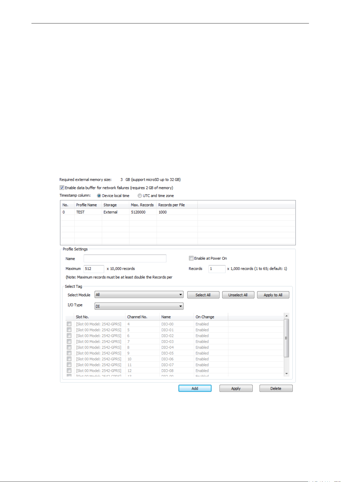
ioLogik 2500 Series Configuration Library
4-28
Data Logging
Install a microSD card in the ioLogik 2500 to use the ioLogik 2500’s data logging function. IOxpress will
calculate the total amount of external memory required; use an SD card with the appropriate amount of
memory.
To use the data buffer function with AOPC, check Enable data buffe r fo r network failures. (Note : this
function requires 2 GB of external memory.) The fo llowi ng values ar e av ail ab le for d ata logg ing : I/O
channels, Internal registers, virtual channels, and serial tags.
Profile
A total of 10 profiles can be created, and multiple/duplicate channels can be included in different prof ile s .
Step1: Define this data logging profile's name.
Step2: Use the Select Tag panel shown below to select channels and then click Add to add those cha nne ls
to a profile.
Step3: If you made changes to the profile settings, click Apply to up date the prof ile settings.
Page 56

ioLogik 2500 Series Configuration Library
4-29
NOTE
The total size of the profiles should be less than the size of the microSD c ard . Otherw is e , the data canno t be
logged
Timestamp column
Each piece of logged data has a time stamp. The timestamp can be set to device local time or UTC and
time zone.
Device Local Time
The ioLogik 2500 will log d ata using the device’s local time, which will be stored in a separate column in the
log file.
UTC and time zone
The ioLogik 2500 will log the UTC time and time zone , which will be stor ed in separate columns in the log
file.
Profile Settings
The selected data will be logged in a profile. The profile name will be used as the folder name on the
microSD card for storing logged data. The profile se tting s allow yo u to selec t the channe l yo u want to log
and configure settings (e.g., Enable at power on and profile Size) for each profile.
The profile is saved to a folder based on the profile name. The filename is based on the creation time.
ftp://IP address of device : port/prof ile name/y yy y/mmddhhxx.csv
• yyyy: year
• mm: month
• dd: date
• hh: hour (24-hour clock)
• xx: sequence number (00 to 99)
Name
The profile name will also be used as the folder name on the microSD card for storing logged data.
Enable at Power On
Enable this function to star t data log g ing at powe r on. Yo u can also use ClicK& Go Plus r ules to
enable/disable the logging features of each profile.
Maximum records
The Maximum records setting puts an upper limit on the amount of data that can be logged. When the
limit is reached, the newest data will over writ e the ol de st da ta.
onto the microSD card. 1,000,000 records require about 1 MB of memory space.
Records per File
The Records per File setting sets an upper limit on the number of records allowed per file. When a particular
file reaches the maximum number of records, the device will create a new file in the same profile folder and
then continue to record data.
Page 57

ioLogik 2500 Series Configuration Library
4-30
Select Tag
For a given profile, you can select which tags you would like to record.
Select Module
You can check ioLogik 2500 and its IO expansion module by using the sele c t mod ule f unction. I f yo u select
ALL, all modules will be selected.
I/O Type
You can select the type of the data you would like to record. Types of data that can be recorded include DI,
Counter, DO, Pulse, AI, Inter nal Reg is te r, Virtual Channel, Serial Tag.
Select All/Unselect All
You can select all channels or unselect all channels with a single click.
Apply to All
You can apply one parameter to all channels. For example, you can change On Change from disable to
enable and then click Apply to All. The On Change enable setting will be applied to all AI channels.
Log Method
• On Change for DI/DO/Pulse/System Tags: The ioLogik will log tag value s to the file whenever the
tag status changes.
• On Change for AI Tag: If the AI is configured to log on change, the percentage se tting s r epre s e nt the
percentage of the full analog range. For example, if the AI is co nfig ured to 0 to 10 V, “On Change 1%”
means the ioLogik will log to file every time there is 0.1 V change
• Interval for Counter/AI/RTD/TC/IR/FIR/VC/Serial Tags: The io Log ik will log tag values to file
when the interval time elapses. The interval time can be config ured to between 5 and 86400 seconds;
the default is 5 seconds.
FTP
The FTP item defines how to log I/O data to an FTP server. The FTP Service function prov ides upload service
for data log files stored o n the Micr oSD card.
Page 58

ioLogik 2500 Series Configuration Library
4-31
NOTE
D
D
FTP Client Settings
The device can act as a client to actively send log files to a predefined FTP server address .
IP (or URL)
The IP address of the FTP server.
Port
The Port number of the FTP server.
Username
The username used to log in to the FTP server.
Password
The password used to log in to the FTP server.
Timeout (ms)
The ioLogik 2500 will disconnect the sess ion w he n this timeout is rea c hed (100 to 65535 ms; default =
1000).
FTP Server Settings
The device can be an FTP server for FTP clients to retrieve logg ed data. The logge d f ile is read-only.
The address to access data will stored in the following address : ftp://IP address of device : port/profile
name/yyyy/mmddhhxx.csv
• yyyy: year
• mm: month
• dd: date
• hh: hour (24-hour clock)
• xx: sequence number (00 to 99)
Enable FTP s er v er
To enable or disable the FTP server function.
Username
The FTP server’s username.
Password
The FTP server’s password.
efault username: admin
efault password: moxa
Click&Go Plus
Click&Go Plus provides the functional elem e nts that c an be used in Click& Go Plus rules, including Timer,
SNMP trap, TCP/UDP message, Email, Schedule, Internal Register, Remote Action, and CGI command. You
must set all of these elements before you start configuring your Click&Go rules. Whe n a set of rules (know n
as a rule-set) is defined using Click& Go Plus, the ioLogik can perform local and remote I/O control, report
I/O status, and actively send out messages, e-mails , or SNMP traps to a host as soon as the user-defined
I/O conditions have been met.
For a detailed introduction on how to use this function, re f er to Chap ter 2 of the Click&Go Plus User’s
Manual.
Page 59
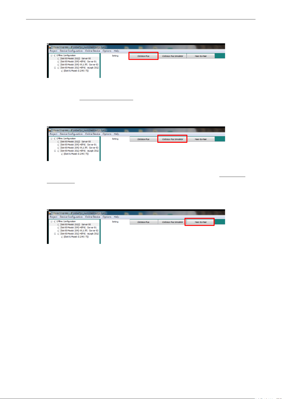
ioLogik 2500 Series Configuration Library
4-32
Click&Go Plus Tab
Click&Go Plus logic provides an easy way to program your ioLogik 2500 product for smarter I /O
functionality over an Ethernet network . For a detailed introduction on how to use Click&Go Plus, refer to
Chapter 3 of the Click&Go Plus User’s Manual.
Click&Go Plus Simulator Tab
When you finish defining your Click&Go Plus r ule s , yo u can use the Click & Go plus Sim ulation to ol to test
the rules. For a detailed introduction of how to use this func tio n, refer to Chapter 4 of the Click&Go Plus
User’s Manual.
Peer-to-Peer Tab
In some remote automation implementatio ns , the co ntro l ro om and field sensors may be located far apart
from each other, often with only a single remote I/O module to co lle c t data from all the sens o rs .
Peer-to-peer communication has little or no limitation since it replaces cab le by integrating multiple I/O
signals over a single network cable to transmit input-to-output controls without the aid of PLCs or
controllers.
With peer-to-peer communication and suppor t for channe l-to-channel mapping, the ioLogik 2500 allow s
simultaneous multiple target transm is s ions. In addition, the ioLogik 2500 supports up to 16 channels for
transmission over Ethernet (based on an emitter and rece ive r I /O pair).
Page 60

ioLogik 2500 Series Configuration Library
4-33
NOTE
If the heartbeat interval is set and the network betw een the
will detect lack of heartbeat, and then disco nne c t the
Click on Peer to Peer in the menu bar to configure basic device settings.
General Settings
Heartbeat (Sec)
Heartbeat is used to determine the connectio n status be tw een Peer-to-Peer devices and to ensure that the
ioLogik 2500 is connected and alive (0 to 655 35 s e c; default = 5).
Tolerance (Sec)
Tolerance allows you to define an additional time out interval to wait for a heartbeat signal from Peer-toPeer devices (0 to 65535 sec; default = 10).
Port
The listen port of the local ioLogik 2500 device for peer-to-p e er func tion (1 to 65535; default = 9300).
Peer-to-Peer devices is down, the ioLogik 2500
Peer-to-Peer connection.
Page 61
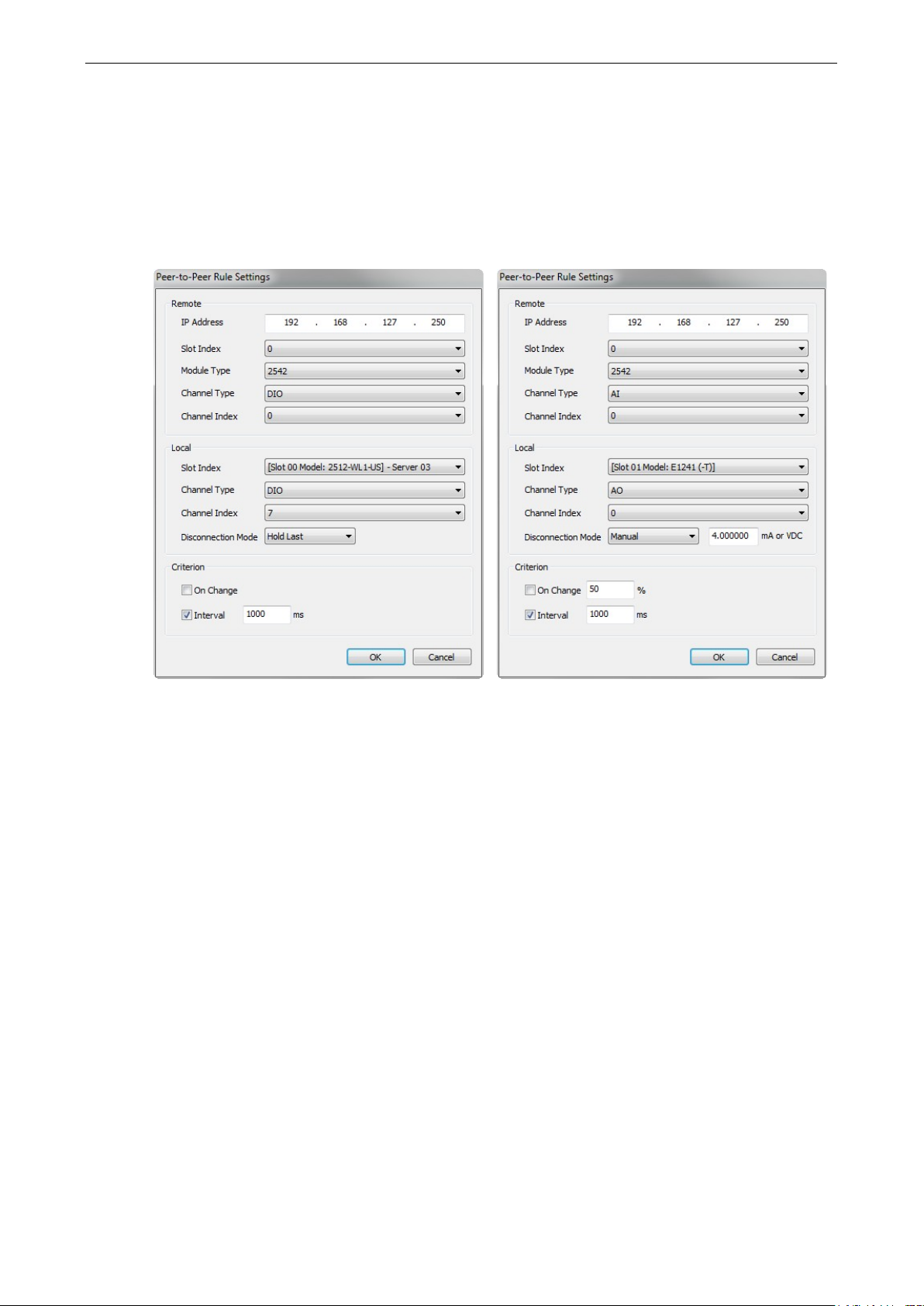
ioLogik 2500 Series Configuration Library
4-34
Peer-to-Peer Rule Settings
With peer-to-peer communication and suppor t for channe l-to-channel mapping, the ioLogik 2500 allows
simultaneous multiple target transm is s ions.
In a Peer-to-Peer rule, the ioLogik 2500 can be configured to receive a signal from a remote site and output
the signal at the local site, allowing you to config ure the remote site information by configuring the IP
address, slot index (for expanded E1200 units), and mod ule type.
Remote
Local
• IP Address: The IP address of the remote device that collects and sends signals.
• Slot Index: An integer used to represent the remote ioLogik 2500 and its E1200 expansion units (0:
the ioLogik 2500 head unit; 1 to 8: the ioLogik E1200 expansion units).
• Module Type: The model name of the remote device.
• Channel Type: The input channel type of the remote device.
• Channel Index: The input channel index of the remote device.
• Slot Index: The local ioLogik 2500 or its E1200 expansion units.
• Channel Type: The output channel type of the local device.
• Channel Index: The output channel index of the local device.
• Disconnec t ion Mode: The output mode when peer-to-peer disconnection occurs (options for DO: ON,
OFF, or Hold Last; options for AO: manual or Hold Last).
Page 62

ioLogik 2500 Series Configuration Library
4-35
NOTE
Up to 16 P
NOTE
You only need to configure peer
peer channel
Criterion
• On change: Triggers the peer-to-peer signal transmission when the status of the DI channel changes or
the value of the AI channel changes by the pre-defined percentage.
• Interval: Triggers the peer-to-peer signal transmission when the interval tim e elaps es (500 to 65535
ms; default = 1000).
eer-to-Peer rules can be set (a set of ioLogik 2500 + up to 8 x ioLogik E1200).
-to-peer rules for output channels on the local ioLogik device . The peer-to-
s at the remote field site will be mapped to automatically.
Page 63

5
5. Device Library
With Device Library, the operator uses IOxpress to export the configurati o n to device s on the netwo rk . That
is, settings that were configured offline are expor te d over the network to o nline devic e s . This can be do ne
either in batch mode, or on a case-by-case basis.
IOxpress can also be used to access online devices directly to check I/O status, upgrade firmware, export
configurations, and restart devic e s.
The following topics are covered in this chapter:
Introduction
Auto-Searching for Online Devices
First Time Searching for Devices
C o nducting another Search for Online Devices
Deployment
Update Configuratio n to Dev ice
Get Configuration from Device
Update Firmware
Set Device Date & Time
R e trieve System Log
Restart Device
Load Factory Default
Change IP Address
Change Device Name
Web Console
Web Console Functi on s
User Interface Introduction
System Information Panel
Menu Panel and We b Pages
Page 64
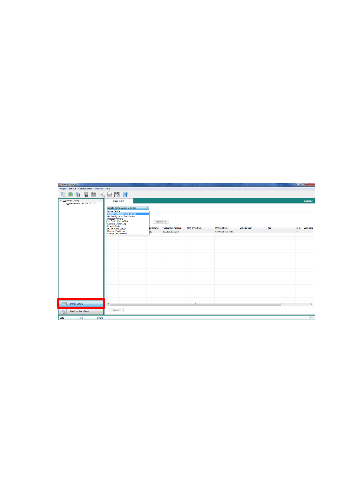
ioLogik 2500 Series Device Library
5-2
Introduction
IOxpress provides an online device management user interface for ioLogik 2500 units that are deployed
online, allowing you to handle all online devices with a single interface.
Online device management can be used to update/export configurations to/from multiple ioLogik 2500
devices. It provides a variety of functions to help you manage multiple devices at the same time, including:
• Locate device
• Update configuration to device
• Get configuration from device
• Update firmware
• Set device date & time
• Retrieve system log
• Restart Device
• Load Factory Default
• Change IP address
• Change Device Name
Page 65

ioLogik 2500 Series Device Library
5-3
Auto-Searching for Online Devices
First Time Searching for Devices
• The first time you start IOxpress, it will open to the Device Library page, IOxpress will automatically
display an auto-search information popup windo w .
• Click Yes to start searching for devices. Uncheck Enable Search Reminder if you don't want to show this
message again.(This can be enabled again under Option Options Search Reminder Settings.)
• The search information will be displayed in the Log .
Conducting another Search for Online Devices
If you would like to conduct another search for online devices , c lic k Search... under the Device tab on the
menu bar.
Page 66
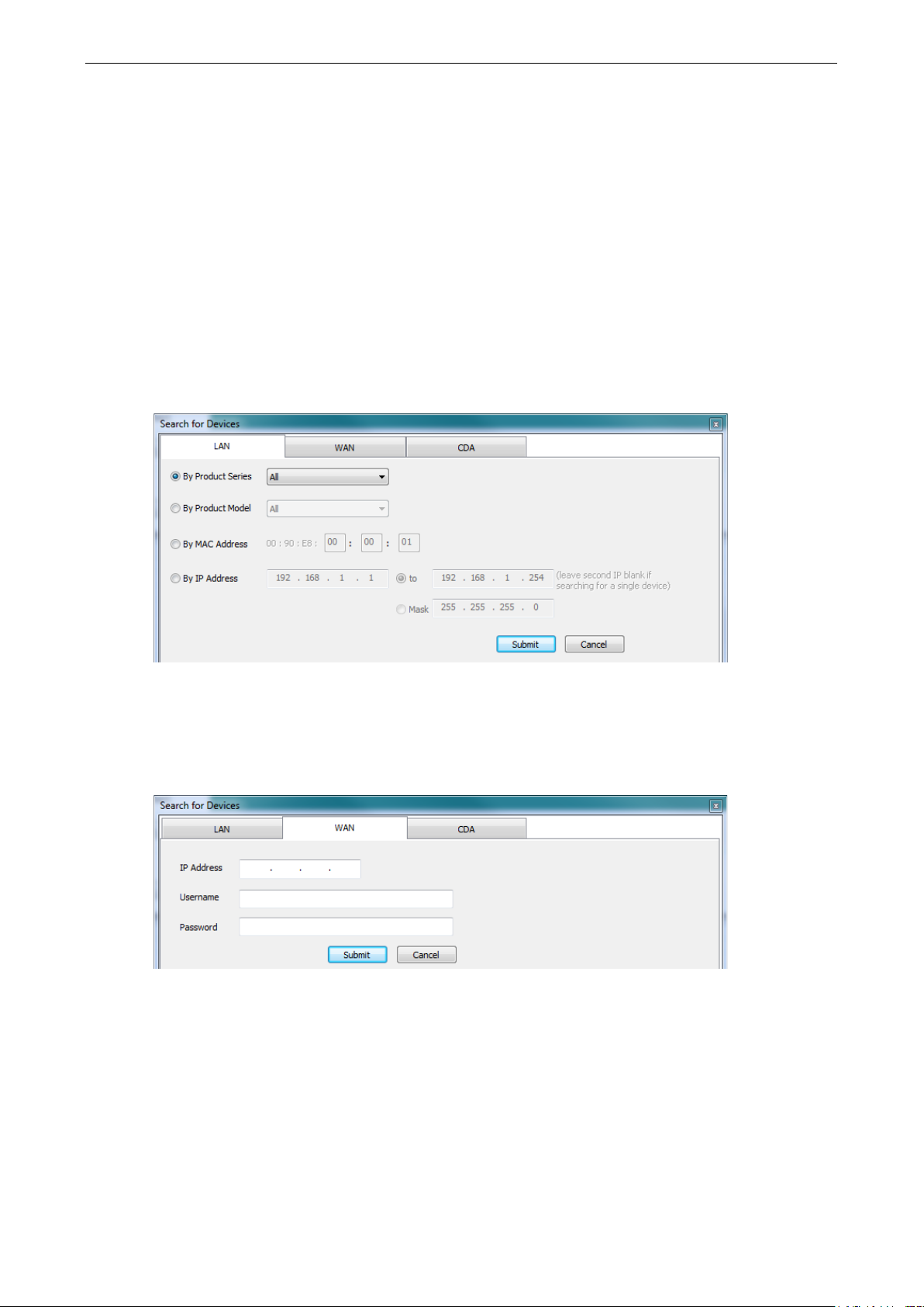
ioLogik 2500 Series Device Library
5-4
The Search function provides three search criteria:
1. LAN
2. WAN
3. CDA
LAN
When searching for devices on the local area network (LA N), use the filte rs located on the LAN tab to
narrow your search to specific devices.
• By Product Series
• By Product Model
• By MAC Address
• By IP Address
WAN
For devices on the wide area network (WAN), click the WAN tab and then enter the IP address, username,
and password to add the device.
Page 67
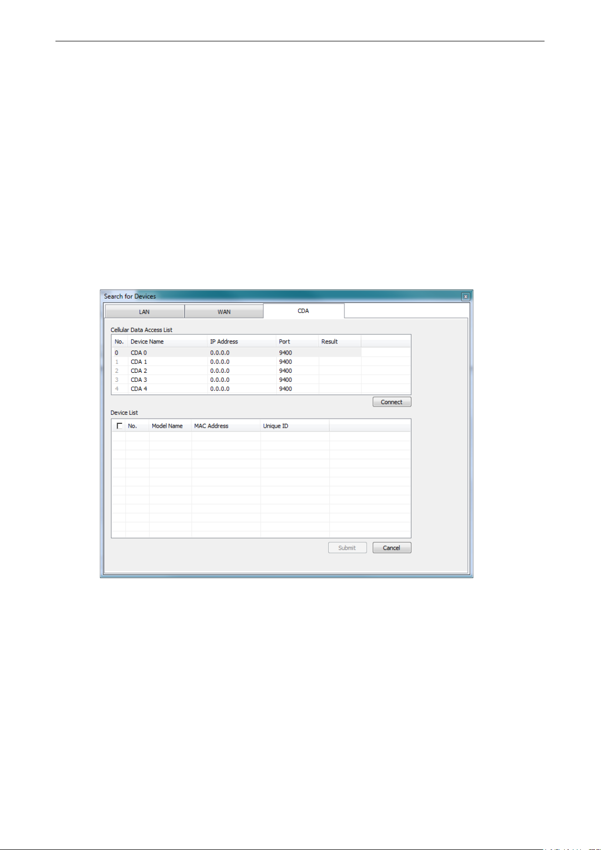
ioLogik 2500 Series Device Library
5-5
CDA
Cellular Data Access is a device gateway that allow s you to estab lis h conne c tions to ioLogik 2500 units
configured with a dynamic public IP. You will need to install C e llular Data Access on a server that is using a
public IP address, and the iologik 2500-GPRS/HS PA unit’ s config uration must have the Cellular Data Access
function enabled. Once the Cellular Data Access a nd ioLog i k 2500 ar e conf igured, you can use “add device
by cellular data access” to add a device registered in the Cellular D a ta Acc ess serv er . Detailed c o nfig uration
instructions can be found in Chapter 6: Cellular Network Setup and Configuratio n (for cellular models).
After configuring the CDA, the CDA server IP and port number can be used on the CDA tab to search for
devices. Follow these steps to conduct a search.
1. Type in the server’s IP address and port number.
2. Click the Connect button.
3. Select the cellular device that you would like to connect to and click submit.
4. The selected device s hav e been added to the online device list, and you can start to upload/configure
your devices over the cellular network.
Page 68

ioLogik 2500 Series Device Library
5-6
NOTE
If you
uncheck the
Deployment
After online devices have been added to the online device list, yo u can then use deplo yment to deploy the
online devices.
Deployment allows you to deploy multiple devic e s at the same time. To execute a deplo yme nt, f i r s t click
Device Library in the left panel, and then click the drop down menu on the right to select the deployment
function. Nine different functions can be used for mass deployment.
• Locate Device
• Update configuration to device
• Get configuration from device
• Update firmware
• Set device date & time
• Retrieve system log
• Restart Device
• Load Factory Default
• Change IP address
• Change Device Name
do not want to change a device’s network settings,
Overwrite Network Setting checkbox.
In the following subsections, we descr ibe in gre a ter deta il how to use these functions.
Page 69

ioLogik 2500 Series Device Library
5-7
NOTE
If the device is Locked, you must log in as administrator to
options. If you have not updated the username and password, use the def a ult
Update Configuration to Device
Use this function to update configurations that were completed using Configuration Library. The ioLog ik’s
system configuration, including the curre nt C lick & Go Plus r ule-set, c an be importe d and expor ted to the
ioLogik 2500 device. You will need to know the user name and password to use this function.
The configuration can be from one of two sources:
Configurations from Configuration Library:
To update a configuration completed in Conf i g uratio n L ib rary, click the Configuration column and select
the configuration you created.
(The configuration name will be shown using the Device Name that was set during the offline
configuration.)
Configurations from a File:
You can update a configuration from a configuration file saved on your computer.
Default User Name: admin
Default password: moxa
Get Configuration from Device
You can get the configuration from an ioLogik 2500 unit and save the configuration to your PC.
Update Firmware
The Firmware Update tab is available after you log in as administrator. Enter the path to the firmware file
or click on the icon to browse for the file. Click Update to update the ioLogik firmware. The wizard will lead
you through the entire process, including res ta r ting the ioLogik.
gain access to the ioLogik’s configuratio n
s:
Page 70

ioLogik 2500 Series Device Library
5-8
Set Device Date & Time
The ioLogik 2500 can be synchronized with PC time, or the time can be set manually. However, regardless
of whether the time was synchronized with PC time or was set manually, the ioLogik 2500 will continue to
connect to an NTP server periodically. Conseq ue ntly, the time will be updated the next time the ioLogik
2500 connects to the NTP server.
Retrieve System Log
The ioLogik 2500 will log the system’s status in the device. When needed, you can retrieve the system logs
and send the logs to the Moxa support team for further analysis. Since the system log is desig ne d to be
analyzed by the Moxa support team, the log will be encoded.
Restart Device
Select this command to restart a selected ioLogi k 2500 .
Load Factory Default
Select this command to reset all settings on the selected io Log ik, including the password and all
configuration settings, to factory default values.
Change IP Address
Use this function to change the IP address of an ioLog ik 2500.
Change Device Name
Use this function to change the server name.
Change IP Address an d Ser ver Name can be used to deploy the same configuration to multiple devices
and change the IPs and Server names of the devices.
Web Console
Use the web console to check the device status. There are two ways to connect to the ioLogi k 2500 web
console.
Direct Access By Browser
The ioLogik 2500 series can be accessed using Internet Explorer (version 9 or above), Firefox, or Google
Chrome to check device status. Type the ioLogik 2500’s IP address in the browser’s address box to access
the unit.
Page 71

ioLogik 2500 Series Device Library
5-9
NOTE
•
Note:
Open Selected Device Web via IOxpr es s
Open the IOxpress graphical user interface and the n select the device you would like to check. Click the
Web Browser icon on the quick launch bar or right click on the selected device and choose Web Console...,
to start IOxpress in the PC’s default browser. In order to ensure that the inf or ma tio n is d isplayed correctly,
please ensure that version 9 or above of Microsoft Interne t Exp lor e r is installe d on your computer.
• Default user name: admin
Default password: moxa
The user name and password are case-sensitive.
Web Console Functions
You can check the device status and also import/export configurations from the web console. The following
section introduces how to use these web console functions.
User Interface Introduction
The web console is divide d into three regions:
1. System informa tio n panel
2. Menu panel
3. Web page panel (the web page associated with the function selected in the Menu panel)
Page 72

ioLogik 2500 Series Device Library
5-10
Click
its expansion modules. The Web page panel should appear similar
to
will depend on the number E1200 modules connected to the
ioLogik 2512.
System Information Panel
The system information panel displays the ioLogik 2500’s system information, including Name, Firmware
versions, IP address, Click&Go status, serial number, MAC address, Connection status, and Date and Time.
Menu Panel and Web Pages
The menu panel includes the following items.
I/O Status
I/O Status to check the I/O status of the io Log ik 25 00 and
figure shown at the right. The number of “slots” that appear
• Click any of the slots (Slot-0, Slot-1, …, Slot-8) to check the I/O status of the device.
• Use the Locate function to identify the physical location of the selected device. The device’s RDY LED
will continuously blink green.
• Use the DI/Counter channels to check the DI/Counter status and reset/start/stop the counter.
• Use the DO/Pulse channels to manually control the DO/Pulse.
Cellular (ioLogik 2500-GPRS/HSPA only)
Use this function to identify the cellular connection status of ioLogik 2500-GPRS/HSPA units.
• There are four cellular connection stages. While a particular stage is in process, the icon of the stage will
be green.
Page 73

ioLogik 2500 Series Device Library
5-11
Click this icon to upgrade the firmware. You can cho
use for the
Click this icon to import a device configuration. You can cho
would like to
Click th
Click this icon to reset the device to factory default.
• The cellular information provid e s the I MEI and RSSI of the cellular c o nnection.
• Once the IP and DNS are received from the ISP, the network information will shown.
• SIM Information shows the current status of the SIM card.
VPN Status (ioLogik 2500-GPRS/HSPA only)
Use this function to identify the VPN connection status of ioLog ik 2500-GPRS/HSPA units.
• You can check VPN status. There are four cellular connection stage s . While a parti c ular stage is in
process, the icon of the stage will be green.
Upgrade
Import
Export
Reset
ose the FWR file you would like to
upgrade.
ose the config file you
use for the upgrade.
is icon to export a device configuration.
Page 74

6
6. Cellular Network Setup and Configuration
(for cellular models)
In this chapter, we introduce how to set up your ioLogik 2500-GPRS/HSPA device.
The following topics are covered in this chapter:
IOxpress Settings for a Cellular Network
Select Network Interface
Cellular
Cellular Network Connect io n
MX-AOPC Server (for SCADA/HMI users)
With D DNS (for SCADA/HMI users)
Mo xa Cellular Data Access Utility (for mobile devices/PC s )
Page 75
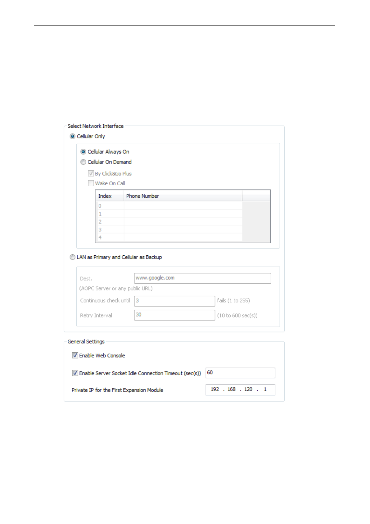
ioLogik 2500 Series Cel lular Network Setup a nd Configuration (for cellular m ode ls)
6-2
IOxpress Setti n g s for a Cellular Network
When you add an ioLogik 2500-GPRS/HSPA model, the following two functions will be available (in addition
to the functions discussed in Chapter 3).
Select Network Interface
Configure your device’s cellular netwo rk se tting s on the Select Network Int er f ace page, whic h is loc ate d
under the Network-General sub-page.
Cellular Only
You can configure under what conditions the ioLo g ik 2500-GPRS/HSPA will connect to the cellular network.
For example, the device could be triggered by a Click&Go Plus rule or by wake on call.
Cellular Always On
This mode allows the ioLogik 2500-GPRS/HSPA to always remain connected to the cellular network.
Page 76

ioLogik 2500 Series Cel lular Network Setup a nd Configuration (for cellular m ode ls)
6-3
Cellular ON Demand
This mode allows the ioLogik 2500-GPRS/HSPA to conserve power by flipping into sleep mode whenever
there is no need to transmit information. When in sleep mode, the ioLogik 2500-GPRS/HSPA disables the
cellular connection and stays in standby mode, s aving all I/O reco rd s in the data log on the SD card. The
ioLogik 2500-GPRS/HSPA will only wak e up whe n either :
1. It receives an activate mess age from Clic k& Go, or
2. It receives a call fro m an authorized c a ller pho ne numb er.
LAN as Primary and Cellular as Backup
By selecting this function, a remote des tination is used in this setting to indicate if the Internet connectio n
is still alive. The user can specify a public IP or URL and the number of retrie s that ar e allo w ed . If the
Ethernet is disconnected, the cellular connection will be triggered as a backup .
Dest IP/URL
This option, which can be configured to either an AOPC server IP or any public URL, will be used by the
device to determine whether or not it is connected to the Interne t.
Continuous Check Until 3 failures
The ioLogik 2500-GPRS/HSPA continuously check its connection with the IP/URL to ensure that it is
constantly connected to the internet (co uld inc ur a hig h cost, dep e nd ing o n your cellula r plan).
Retry Interval
The “retry interval” is the time interval be twee n retrie s .
Cellular
Cellular network settings are config ured o n the “cellular” page, which is located under “Network.”
General
To set up your cellular connection, click the Cellular Settings tab and enter your User name, Password,
SIM pin code, and APN of your Cellular Provid er (conta c t your local Cellular Service Provider for
assistance).
Page 77
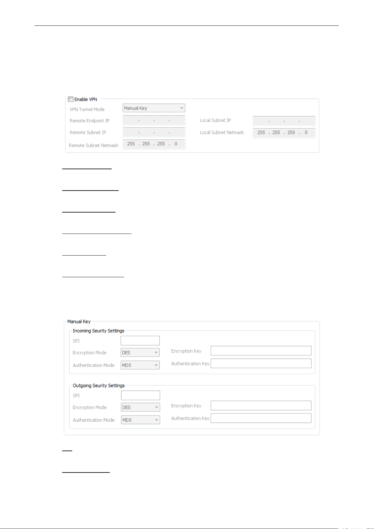
ioLogik 2500 Series Cel lular Network Setup a nd Configuration (for cellular m ode ls)
6-4
VPN
In this section, we exp lain how to set up a VPN connection for the ioLogi k 2500-GPRS/HSPA.
Enable VPN
VPN Tunnel Mode
The type of VPN tunnel policy to be used; either manual key IPsec or ISAKMP with Pre-shared Keys (PSK).
Remote Endpoint IP
Enter the WAN IP of the remote VPN server endpoint.
Remote Sub n et IP :
Enter the remote VPN server subnet (LAN) IP of the remote network.
Remote Sub n et netmask
Enter the remote VPN server subnet netmask of the remote network.
Local subnet IP
Enter the ioLogik 2500’s subnet (LAN) IP.
Local Subnet netmask
Enter the ioLogik 2500’s subnet netmask.
Manual Key
SPI
Set the VPN manual key for incoming/outgoing SPI betwe e n 257 and 42949672 95 .
Encryption mode
Select the incoming/outgoing encryption mode.
Page 78
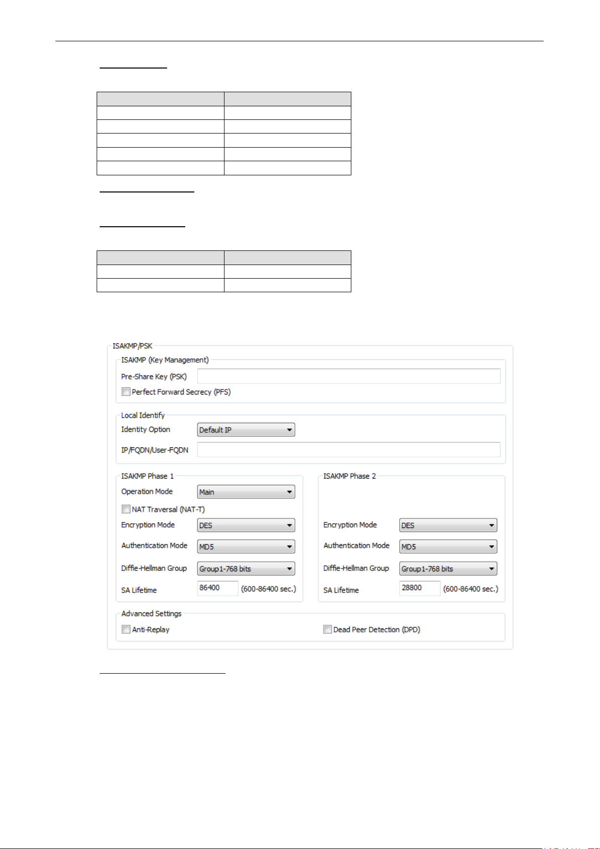
ioLogik 2500 Series Cel lular Network Setup a nd Configuration (for cellular m ode ls)
6-5
Encryption key
Enter the incoming/outgoing encryp tion key.
Encryption mode Length (bytes)
DES 8
3DES 24
AES 128bit 16
AES 192bit 24
AES 256bit 32
Authentic ation mode
Select the incoming/outgoing authentication mode.
Authentic ation key
Enter the incoming/outgoing authenticatio n k e y.
Authentic ation mode Length (bytes)
MDS 16
SHA1 20
ISAKMP/PSK
ISAKMP (Key Management)
Pre-shared key (PSK): Sets the VPN ISAKMP Pre-Shared key settings.
Perfect forward secrecy (PFS) (default = Disable): Enable or disab le the Perfe c t Forwar d Sec recy . PFS
as an additional security protocol.
Page 79

ioLogik 2500 Series Cel lular Network Setup a nd Configuration (for cellular m ode ls)
6-6
Local Identity
Identity option: Select additional ID authentication requirements for the VPN using a specific IP Address,
FQDN, or User FQDN settings.
IP/FQDN/User_FQDN: Enter an ID (IP/FQDN/User_FQDN) to identif y and authenticate the local VPN
endpoint.
ISAKMP phase 1
Operation mode: Select main mode or aggressive mode to configure the standard negotiation parameters
for IKE Phase 1 of the VPN Tunnel.
NAT-T (default = Disable) : Enabling this option will allow IPSec traffic from this endp oint to traverse
through the translation process d uring NAT. The remo te VPN endpoint must also support this feature and it
must be enabled to function properly over the VPN.
Encryption mode: Select the VPN ISAKMP phase 1 encryption mode.
Authentic ation mode: Select the V PN ISA KMP phase 1 authentic ation mode.
Diffie-Hellman group: Select the VPN ISAKMP phase 1 DH group. As the DH Group number increases, the
higher the level of encryption implemented for PFS.
SA life time (default = 86400): Enter the number of seconds for the VPN ISAKMP phase 1 Lifetime. This
is the period of time that passes before establishing a new IPSec security association (SA) with the remote
endpoint.
ISAKMP phase 2
Encryption mode: Select the VPN ISAKMP phase 2 encryption mode. Authentication mode: Select the
VPN ISAKMP phase 2 authentication mode.
Diffie-Hellman group: Select the VPN ISAKMP phase 2 DH group. As the DH Group number increases, the
higher the level of encryption implemented for PFS.
SA life time (default = 28800): Enter the number of seconds for the VPN ISAKMP phase 2 Lifetime. This
is the period of time that passes before establishing a new IPSec security association (SA) with the remote
endpoint.
Advanced settings
Anti-replay (default = Disable): Anti-replay is the method of not allowing an intercepted packet
message to be sent to the recipient multiple times without the or iginal sender knowing about it.
Dead Peer Detec ti o n ( DPD) (default = Disable): Enable or disable Dead Peer Detection. DPD is a
method of detecting a dead Internet Key Exchange (I KE) peer . It sends a DPD packet to the peer every 60
seconds under no traffic and attempts to connect normally. If the DPD packet fails 5 times the VPN will
continuously re-estab lis h a connection.
Page 80

ioLogik 2500 Series Cel lular Network Setup a nd Configuration (for cellular m ode ls)
6-7
NOTE
If using a URL, you may need to configure
Reconnection
Carriers disconnect idle mobile dev ic e connec tions in order to save bandwidth for other on-line users and
applications. To keep the ioLogik 2500-GPRS/H S PA alway s On, the io Log ik 2500-GPRS/HSPA must not only
have the capability to detect the cellular conne c tion and reconnect to the network once it is disconnected,
but also needs to send out signals (ICMP package) to notify carr ier s that the io Log ik 2500-GPRS/HSPA is
still alive.
Dual SIM Failover Mode
When the Dual SIM Failover Mode checkbox is selected, the ioLogik 2500-GPRS/HSPA will switch from
one SIM card to the other when a connection cannot be established using the ac tive SIM card .
If the function is disabled, only SIM1 is activ ated when two SIMs are installed.
Reconnect cellular network after 3 ping failures
The device will keep pinging Dest.IP/URL after an Internet connection is es tab lished. If the ping fails three
times, the ioLogik 2500-GPRS/HSPA wil l s tart the GSM reconnection process.
Dest IP/URL
Can either be an AOPC server IP or any public URL for the device to check its connec tio n with the inter ne t.
Ping Interval
The ioLogik 2500-GPRS/HSPA will ping the Dest IP/URL at regular intervals to check for an Internet
connection.
DNS through Network LAN IP Settings.
Restart device after reconnection fails for X hours (1 to 24)
If rebooting the Reconnect cellular network after ping failure does not reestablish your connection, the
disconnection may be caused by a higher layer communicatio n pr ob le m . In this case, you can select
Restart device after reconnection failure for any time interval from 1 to 24 hours. The ioLogik 2500GPRS/HSPA will restart the device.
Page 81
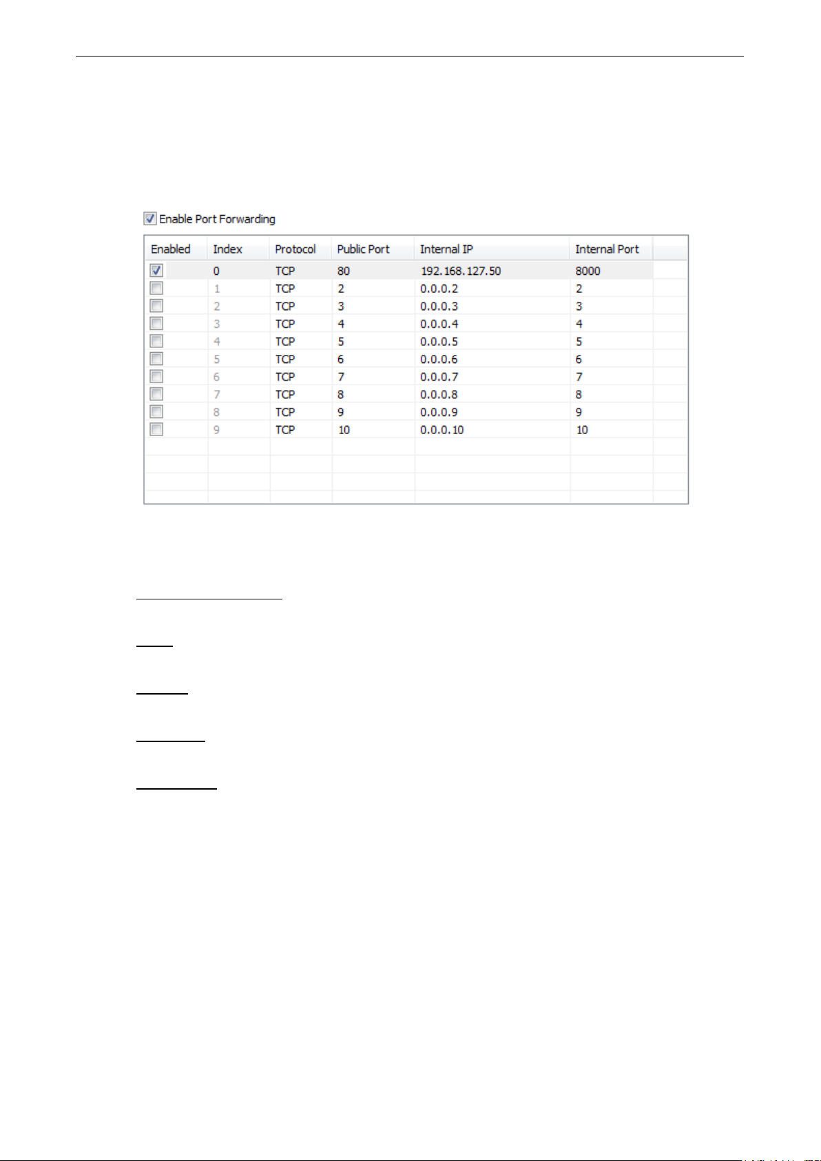
ioLogik 2500 Series Cel lular Network Setup a nd Configuration (for cellular m ode ls)
6-8
Port Forwarding
The ioLogik 2500-GPRS/HS PA supp or ts port for w ard i ng on its ce llula r a nd Ether ne t inter fac e s for WAN-toLAN communication. Using port forwarding , the ioLogik 2500-GPRS/HSPA allows external WAN hosts such
as SCADA/HMI systems to connect to specific field devices within the LAN by linking with the ioLogik 2500GPRS/HSPA.
Ethernet packages from public ports will be forwarded to the assigned Interna l IP and Interna l Po rt. In the
example shown above, Ethernet packets from the ioLogik 2500’s p ort 80 will be forwarded to
192.168.127.50:8000 (IP: 192.168.127.50; Port: 8000).
Enable Port Forwarding
Enable or disable the port forwar d ing f unc tion.
Index
The port forwarding rules index for identification, cannot be changed.
Protocol
Choose which Ethernet protocol will be forwarded. You ca n choose either TCP or UDP.
Internal IP
The destination IP that Ethernet packets will be forwarded to.
Internal Po rt
The destination port that Ethernet packets will be forwarded to.
Page 82

ioLogik 2500 Series Cel lular Network Setup a nd Configuration (for cellular m ode ls)
6-9
DDNS
The purpose of DDNS is to provide you with an alternative cost effec tive cellular plan. You will not need to
establish a server or pay for a Static IP. Setting up DDNS allows the ioLog ik 2500-GPRS/HSPA to behave
like a server and perform functions such as email, ftp, etc. Regardless of whether the device has a floating
IP or a private IP, the user can establish a connection with their remote device through DDNS. DDNS allows
the SCADA/HMI server to establish a connection thro ug h the DDN S serve r to find the remote dev ic e .
Service Provider (default=DynDns.org)
Currently, DynDns.org is the only optio n available for Server address.
Host name
Enter the name you created on www.dyndns.com in this field . The ioLo gik 2500-GPRS/HSPA will update the
DynDNS server with this host name.
Username
This is the user name used for updating DDNS Server authentication.
Password
This is the password used for updating DDNS Server authentication.
Cellular Data Access
The Cellular Data Access setting is used for conne c ting to Moxa cellular data access utilities.
For detailed information on how to set up the cellular data acce s s serve r, see the next section, Moxa
Cellular Data Access Utility.
IP address
Enter the IP address of the cellular data access server.
Port
Enter the port number of the cellular data access server.
Page 83

ioLogik 2500 Series Cel lular Network Setup a nd Configuration (for cellular m ode ls)
6-10
Unique ID
The unique ID is used for remote action functions. For detaile d info rmation, refer to the Click&Go Plus
User’s Manual.
Heartbeat (sec.)
The heartbeat is used to determine whether or not the connectio n betw e e n an ioLog ik device and the
cellular data access server is still active.
Cellular Network Connection
The dynamic IP addresses commonly used for cellular c onnections make it hard for control systems to link
to cellular data acquisition device s . W ith Moxa ’ s MX-AOPC server, SCADA/HMI users can easily connect to
field I/O devices. For web-based applications, Moxa’ s cel lular data access utility provides an ideal way to
seamlessly connect to remote cellular IO units.
MX-AOPC Server (for SCADA/HMI users)
To allow private networks to get around the connectivity issues raised by edge devices configured with
dynamically assigned private IP addre sse s , typ ic ally ope rators purchase high-cost static IP addresses for
each device, with IPs provided by a DDNS or VPN service purchased from an MVNO (Mobile V irtual N e tw or k
Operator). Even with DDNS technology, SCAD A syste m s need to assig n reso ur ces to manage the DDNS
servers. As an alternative, Moxa’s Cellular remote I/O dev ices us e Moxa’ s prop r ie tary “pus h” technology,
called MX-AOPC Server.
With Moxa’s powerful MX-AOPC Server support, communications e ff ic ie ncy betw een ioLogik 2500GPRS/HSPA devices and the central SCADA are substantiall y improved. Moxa’s MX-AOPC Se r ver’s nonpolling communications archite c tur e sup ports the standa rd OPC pro to co l, b ut ins te ad of requiring the
SCADA to poll edge devices it allows edge devices to active ly push comm unic ations to the central
HMI/SCADA system, empowering the network with re al time I/O update s while subs ta ntially cutting
network overhead.
Unlike the requirements of a traditional OPC serve r (w here remo te I/O devices must use a static IP so they
may be successfully polled), MX-AOPC Serve r and ioLog ik products allow engineers the flexibility of
configuring edge devices with dynamic IP address es. Eve n when us ing DHC P addre ssing, ioLogik devices
can push messages back to the OPC server, allowing wide area I /O netwo rk s using dy namic IP cellular
accounts. Using traditional po lling O PC ap p lic a tio ns , I /O device s c anno t make use of this appro ac h.
Page 84

ioLogik 2500 Series Cel lular Network Setup a nd Configuration (for cellular m ode ls)
6-11
With DDNS (for SCADA/HMI users)
In addition to using MX-AOPC Server to register an ioLogik ioLogik 2500-GPRS/HSPA with SCADA over a
dynamic IP cellular connection, yo u may also use DDNS to configure the device with a unique URL. The
ioLogik 2500-GPRS/HSPA can be configur ed to reg is ter a DNS hostname (i.e . – URL) w ith DD NS, and
thereby convert a dynamic IP to a publicized address. I n this way, centr aliz e d co ntro l software will be able
to connect to the remote ioLogik 2500 GPRS/HSPA without requiring a fixed IP or VPN service from a
network provider.
Moxa Cellular Data Access Utility (for mobile devices/PCs)
With the Moxa cellular data access utility, you can config ure the i oLogik 2500-GPRS/HSPA using the
IOxpress utility over the cellular network. You can also log on to selected ioLogik 2500 device s by us ing a
specific URL port. In this section, we exp lain how to use these two metho ds to connect devices.
Step1: Installing Cellular Data Access Utility on a server PC
Cellular Data Access Utility is a Windows utility provided for connecting and managing the ioLogik 2500-
GPRS/HSPA over a cellular network. Cellular D ata Acce s s Utility can be used from anywhere on the network
to monitor and configure the ioLogik 2500-GPRS/HSPA.
Downloading from Moxa’s Website
Click the following link: http://www.moxa.com/support/search.aspx?type=soft.
Enter the name of the product you have purchased into the search bar or select it from the dropdown menu,
and after navigating to the product page click on Utilitie s , in the m iddle of the pag e , loc ated in the box
titled Software.
Download and then unzip the file, and then run SETUP.EXE from that location.
The installation program will guide you through the installation process and install the softwar e . After the
installation is finished , run the softw are fro m the Window s Start m e nu.
Step2: Use “offline configuration” to set up the ioLogik 2500GPRS/HSPA
Before you start using the cellular data access utility, set up the “cellular data access” function. See the
Cellular Data Access section in this chapter for details.
Page 85

ioLogik 2500 Series Cel lular Network Setup a nd Configuration (for cellular m ode ls)
6-12
Step3: Connect to the device over the cellular network
Using IOxpress
Connect to the cellular Data Access server using Device Library, as described below:
1. Click Device Management.
2. Click the Search icon on the quick launch bar and select the CDA tab.
3. Type in the server’s IP address and port number.
4. Click the Connect checkbox.
5. Select the cellular device that you would like to connect to and then click submit.
6. The selected devices have been added to the online device list, and you can start to upload/configur e
your devices over the cellular network.
Using a browser URL
1. Check the port number in the cellular d a ta acce s s utility .
Once the devices are connected, the utility w ill automatically assign URL ports to the devices.
2. Access the device via the browser.
You can use the URL to connect to the device by typing http://[IP address] : [Port].
IP Address: The IP address of the Cellular Data Access server.
Port: The port number of the device assigned by Cellular Data Acc ess .
E.g., 192.168.17.253:20002
Page 86

7. Wireless LAN Network Setup and
Configuration (for wireless LAN models)
In this chapter, we introduce how to set up your ioLogik 2500-WL1 device.
The following topics are covered in this chapter:
Deploying the ioLogik 2500-WL1
IOxpress Settings for a Wireless LAN Network
Wireless LAN
7
Page 87

ioLogik 2500 Series Wireless LAN Network Setup a nd Configuratio n (for wireless LAN models)
7-2
ATTENTION
Be sure to eliminate loops from networks that consis t of wireles s br idg es, Ethernet switches, Ethernet links,
and
be seriously degraded. The following fig ure s how s a network to po log y co nta ining a loop.
Deploying the ioLogik 2500-WL1
For testing requirements, we strong ly s ugg est that yo u prepar e a wirel ess LAN adap ter . Af ter finis hing the
installation and configuratio n, yo u should te s t the ioLogik 2500-WL1 to make sure the wireless transmission
is working normally.
Step 1: Set up the computer’s IP addr ess, and the connect ioLogik 2500-WL1 to a notebook or
PC.
In a Windows environment, the computer’s IP address can be chang ed in the TCP/IP settings window.
Select an IP address on the same subnet as the ioLogik 2500-WL1. Since the ioLogik 2500-WL1’s default IP
address is 192.168.127.253, and the subnet ma sk is 255.25 5.255.0, you should set the IP address of the
computer to 19 2.168.127.xxx.
Step 2: Use the IOxpress utility to configure the ioLogik 250 0-WL1.
See the following section to learn how to use IOxpress to configur e the io Log ik 2500-WL1’s f unc tions.
Wireless LAN links. If any loops exist, packets will circle around the loop s and network perf ormance will
IOxpress Setti n g s for a Wireless LAN Net w ork
Wireless LAN
When you add an ioLogik 2500-WL1 model to your network, the following two functions will be availab le (in
addition to the functions discussed in Chapter 3).
Cellular network settings are config ured o n the “cellular” page, which is located under “Network.”
Basic
The Basic tab is used to add and edit RF type, channel width, and SSID.
Page 88

ioLogik 2500 Series Wireless LAN Network Setup a nd Configuratio n (for wireless LAN models)
7-3
NOTE
The model name of the ioLogik 2500
the country code. The country code
We use ioLogik 2500
that appear on your computer screen may be different than the one
RF Type
SSID
Setting Description Factory Default
B Supports IEEE 802.11 b only B/G Mixed
G Supports IEEE 802.11g only
B/G Mixed Supports both IEEE 802.11b/g standards, but 802.11g will
operate more slowly when 802.11b clients are on the network
Channel Width
Channel Width
Setting Description Factory Default
20 MHz Select your channel width. Currently, the ioLogik 2500’s Wi-Fi
connection only supports 20 MHz.
SSID
An SSID is a unique identifier that wireless networking devices us e to establis h and maintain w ir e le ss
connectivity. Multiple ac ces s points o n a network or sub-netw or k can use the sam e SSID s.
SSID
Setting Description Factory Default
Max. of 31 characters The SSID of a client and the SSID of the AP must be identical
for the client and AP to be able to communicate with each
other.
20 MHz
MOXA
-WL1-US as an example in the following figures. (The co untr y code and mod e l name
-WL1 is shown as ioLogik 2500-WL-XX in IOxpress, where XX indicates
indicates the ioLogik 2500-WL1 version and which bandwidth it uses.
s shown here.)
Security
The ioLogik 2500-WL1 provides fo ur s tand ardized wireless security modes: Open, WEP (Wired Equiv ale nt
Privacy), WPA (Wi-Fi Protected Access), and WPA2.
Security Mode
Open
No authentication, no data encryption.
For security reasons, users should NOT set the sec urity mode to Ope n System , s inc e authentic ation and
data encryption are NOT performed in Open System mode.
WEP
Static WEP (Wired Equivalent Privac y ) keys must be co nfig ure d manually.
According to the IEEE 802.11 standard, WEP can be used for authentic ation and data encryption to
maintain confidentiality. Shared (or Shared Key) authentication type is use d if WEP authenticatio n and
data encryption are both needed. Normally, Open (or Open System) authentication typ e is us ed when
WEP data encryption is run with authentication.
Page 89

ioLogik 2500 Series Wireless LAN Network Setup a nd Configuratio n (for wireless LAN models)
7-4
HEX
Specifies WEP keys in hex-decimal number format
When WEP is enabled as a security mode, the length of a key (the so-called WEP seed) can be specified as
64/128 bits, which is actually a 40/104-bit secret key with a 24-bit initialization vector. The ioLogik 2500WL1 provides 4 entities of WEP key settings that can be selecte d to use with Key index. The selected key
setting specifies the key to be used as a send-key for encrypting tr affic from the AP side to the wireless
client side. All 4 WEP keys are used as receive-keys to decrypt traffic fro m the wire le s s client side to the AP
side.
The WEP key can be presented in two Key types, HEX and ASCII. Each ASCII character has 8 bits, so a 64bit WEP key contains 5 characters, and a 128-bit key has 13 charac ter s . In hex , each characte r uses 4 bits ,
so a 64-bit key has 10 hex characte rs, a nd a 128-bit key has 26 char acters.
Authentication type
Setting Description Factory Default
Open Data encryption is enabled, but without authentic ation Open
Shared Data encryption and authentication are both enabled.
Key type
Setting Description Factory Default
HEX
ASCII Specifies WEP keys in ASCII format
Key lengt h
Setting Description Factory Default
64 bits Uses 40-bit secret keys with 24-bit initialization ve c tor 64 bits
128 bits Uses 104-bit secret key with 24-bit initialization vector
Key index
Setting Description Factory Default
1-4 Specifies which WEP key is used Open
WEP key 1-4
Setting Description Factory Default
A string that can be used as a WEP seed for the RC4
encryption engine.
ASCII type:
64 bits: 5 chars / 128 bits: 13chars
HEX type:
64 bits: 10 hex chars / 128 bits: 26 hex chars
WPA/WPA2-Personal
Also known as WPA/WPA2-PSK. You will need to specify the Pre-Shared Key in the Passphrase field, which
will be used by the TKIP or AES engine as a master key to generate keys that actually encrypt o utgoi ng
packets and decrypt incoming packets.
WPA (Wi-Fi Protected Access ) and WPA2 repr ese nt s ig nific ant im p ro ve me nts over the WEP encry p tion
method. WPA is a security standard based on 802.11i draft 3, while WPA2 is based on the fully ratified
version of 802.11i. The initial vector is tra ns mitte d, encrypted, and enhanced with its 48 bits, twice as long
as WEP. The key is regularly changed so that true session is sec ured.
Even though AES encryption is only included in the WPA2 standar d, it is widely available in the WPA
security mode of some wireless APs and clients as we ll. The ioLogik 2500-WL1 also supports AES algorithms
in WPA and WPA2 for better compatibility.
None
Page 90
ioLogik 2500 Series Wireless LAN Network Setup a nd Configuratio n (for wireless LAN models)
7-5
Personal versions of WPA/WPA2, also known as WPA/WPA-PSK (Pre -Shared Key), provide a simple way of
encrypting a wireless connection for high confidentiality. A Passphrase is used as a basis for encryption
methods (or cipher types) in a WLAN connection. The passp hrases should be complicated and as long as
possible. The Passphrase must have at least 8 ASCII characters, and can have as many as 63. For security
reasons, this pass p hras e sho uld o nly be disc losed to users who need it, and it should be changed regularly.
WPA/WPA2-Enterprise
WPA type
Setting Description Factory Default
Personal Provides Pre-Shared Key-enabled WPA and WPA2 Personal
Enterprise Provides enterprise-level sec urity for WPA and WPA2
Encryption method
Setting Description Factory Default
TKIP Temporal Key Integrity Protocol is enabled TKIP
AES Advance Encryption System is enabled
Passphrase
Setting Description Factory Default
8 to 63 characters Master key to generate keys for encryption and decryption None
EAP Protocol
Setting Description Factory Default
TLS Specifies Transport Layer Security protocol TLS
TTLS Specifies Tunneled Transport Layer Security
PEAP Specifies Protected Extensible Authentication Protocol, or
Protected EAP
WPA/WPA2-Enterprise
Also called WPA/WPA2-EAP (Extensible Authentication Protoc o l). In addition to device-based authentication,
WPA/WPA2-Enterprise enables user-b as ed authe ntic ation via IEEE 802.1X. The ioLogik 2500-WL1 can
support three EAP methods: EAP-TLS, EAP-TTLS, and EAP-PEAP.
By setting WPA type to Enterprise, you can use EAP (Extensible Authentication Pro tocol), a framework
authentication protocol used by 802.1X to prov ide ne two rk authenticatio n. In these Enterprise-level security
modes, a back-end RADIUS (Remote Authentication Dial-In User Service) server is needed if IEEE 802.1X
functionality is enabled in WPA /WPA2. The IEEE 802 .1X protoco l als o offe rs the poss i b ility of carrying out
an efficient connection authentication on a large-scale network. It is not necessary to exchange ke ys or
passphrases.
WPA type
Setting Description Factory Default
Personal Provides Pre-Shared Key-enabled WPA and WPA2 Personal
Enterprise Provides enterprise-level sec urity for WPA and WPA2
Encryption method
Setting Description Factory Default
TKIP Temporal Key Integrity Protocol is enabled TKIP
AES Advanced Encryption System is enabled
Passphrase
Setting Description Factory Default
8 to 63 characters Master key to generate keys for encryption and decryption None
Page 91

ioLogik 2500 Series Wireless LAN Network Setup a nd Configuratio n (for wireless LAN models)
7-6
MS-CHAP-V2
Microsoft CHAP version 2 is used
EAP-TLS
TLS is the standards-based successor to Secure Socke t Layer (SS L). It c an establish a trusted
communication channel over a distrusted ne twor k . TLS provid e s mutual authe ntic ation through certificate
exchange. EAP-TLS is also secure to use. You are required to submit a digital certificate to the
authentication server for validation, but the authentication server must also supply a certificate .
EAP Protocol
Setting Description Factory Default
TLS Specifies Transport Layer Security protocol TLS
TTLS Specifies Tunneled Transport Layer Security
PEAP Specifies Protected Extensible Authentication Protocol, or
Protected EAP
EAP-TTLS
It is usually much easier to re-use existing authenticatio n s ystems, such as a Windows domain or Active
Directory, LDAP directory, or Kerberos real m, rathe r than cre ating a parallel authentication system. As a
result, TTLS (Tunneled TLS) and PEAP (Protec ted EAP) are used to support the use of so-called “legacy
authentication methods.” TTLS and PEAP work in a similar way . First, they establish a TLS tunnel (EAP-TLS
for example), and validate whether the network is trus tworthy with digital certificates on the authentication
server. This step establishes a tunnel that protec ts the next step (or “inner” authentication), and
consequently is sometimes referred to as “outer” authenti c ation. The TLS tunnel is then used to encrypt an
older authentication protoco l that authentica te s the us e r for the ne twork .
As you can see, digital certificates are still need e d for outer authentication in a simplified form. Only a small
number of certificates are required, which ca n be gener ate d by a small cer tificate authority. Certificate
reduction makes TTLS and PEAP much more popular than EAP-TLS.
The ioLogik 2500-WL1 provides some non-cryptographic EAP methods, including PAP, CHAP, MS-CHAP,
and MS-CHAP-V2. These EAP me thods a r e not recommended for direct use o n w ireless networks. However,
they may be useful as inner authentication methods with TTLS and PEA P.
Because the inner and outer authentications can use disti nc t us e r name s in TTLS and PEAP, you can use an
anonymous user name for the outer authentication, w ith the tr ue user name only shown through the
encrypted channel. Keep in mind that not all clie nt softw are suppo rts anonymous alteration. Confirm this
with the network administrator before yo u enable ide nti ty hiding in TTLS and PEAP.
TTL Inner Authentication
Setting Description Factory Default
PAP Password Authentic ation Protocol is used MS-CHAP-V2
CHAP Challenge Handshake Authentication Pro toc o l is used
MS-CHAP Microsoft CHAP is used
Anonymous
Setting Description Factory Default
Max. of 31 characters A d is tinc t na me used for oute r authe ntic ation None
User name & Password
Setting Description Factory Default
User name and password used in inner authentication None
Page 92

ioLogik 2500 Series Wireless LAN Network Setup a nd Configuratio n (for wireless LAN models)
7-7
20 dBm
PEAP
There are a few differences in the TTLS and PEAP inner authentication procedures. TTLS uses the encrypted
channel to exchange attribute-value pairs (AVPs ), w hi le PEAP use s the encr yp te d channe l to s tart a second
EAP exchange inside of the tunnel. The ioLogik 2500-WL1 provides MS-CHAP-V2 merely as an EAP method
for inner authentication.
Inner EAP protocol
Setting Description Factory Default
MS-CHAP-V2 Microsoft CHAP version 2 is used MS-CHAP-V2
Anonymous
Setting Description Factory Default
Max. of 31 characters A dis tinc t name used for oute r authe ntic a tio n None
User name & Password
Setting Description Factory Default
User name and password used in inner authentication None
Advanced
Additional wireless-relate d paramete rs are presented in this section to help you set up your wireless
network in detail.
Advanced Setting s
Transmission Rate
Setting Description Factory Default
Auto The device s e nses and adjusts the d a ta rate automatical ly Auto
Transmission Power
Setting Description Factory Default
3 dBm to
Fragmentation threshold
Setting Description Factory Default
256 to 2346 Specifies the maximum size of a data packet before splitting
RTSreshold
Setting Description Factory Default
256 to 2346 Determines how large a packet can be before the Access
WMM
Setting Description Factory Default
Enable/
Disable
The device a d j us ts the transmission power 10 dBm
2346
and creating another new packet
2346
Point coordinates transmission and reception to ensure
efficient communication
WMM is a QoS standard for WLAN traffic. Voice and video
data will be given priority bandwidth when enabled with WMM
supported wireless clients.
Enable
Turbo Roaming
Setting Description Factory Default
Enable/ Disable Moxa’s Turb o Roaming can enable rapid handover when the
device, as a client, ro am s among a gro up of APs.
Disable
Page 93

ioLogik 2500 Series Wireless LAN Network Setup a nd Configuratio n (for wireless LAN models)
7-8
AP Alive Check
AP alive check will check if the AP connection is still ava ilab le. Whe n this function is enabled, a check will be
done every 10 ms.
AP Candidate Thres hol d
After the “AP alive check” declares the curre nt access po int is no longer av a ilable, the surrounding access
points must have good enough connection qualitie s (S NR/S ignal S trength) in order to be qualified as AP
candidates for association.
Roaming Threshol d
Determines when to start looking for new AP candidate s. If the current connection quality (SNR or Signal
Strength) is lower than the specified thres hold , the ioLogik will start background scanning and look for
next-hop candidates.
Roaming Difference
Determines if roaming should be executed. After a background scan has been triggered , the roam ing will
only occur if the AP candidate(s) provide a better (Ro am ing difference) connection quality than the current
connection. If multip le acce ss po ints fulfill the criteria, the ioLogik will pick the best one to ro am to.
Scan Channels
You can set up Scan channels for the APs among which this client is going to roam. There are three Sc an
channels available.
Note that the Scan channels may need to be modified when the RF type is changed. (For example, channel
36 is not available in B, G, or B/G Mix mode.)
Page 94

A. Network Port Usage
Remote Action Function
TCP
9010
NOTE
•
The ioLogik 2500 uses the following network ports:
Usage Type Port User-Defined
Serial Tunnel Client TCP 1
FTP Client TCP 21
FTP Server TCP 21
Web Console TCP 80
SNMP Server TCP 161
SNMP Client TCP 162
Modbus Communication TCP 502
SMTP TCP 587
Serial Tunnel Server TCP 4001
Auto Search Function UDP 4800
TCP/UDP Message
TCP 9000
UDP 9000
A
Peer-to-peer Function TCP 9300
IOxpress TCP 10124
AOPC Protocol*
*The ioLogik 2500 series only supports MX-AOP C UA server.
• Client refers to when the ioLogik 2500 is acting as a client to conne c t othe r ser v i ces.
Server refers to when the ioLogik 2500 is acting as a server to provide services to other devices.
TCP 9500
TCP 9900
Page 95

B. Modbus/TCP Default Address Mappings
NOTE
The Modbus/TCP ID of the io
Address
Reference
The following topics are covered in this appendix :
• ioLogik 2512 Series Modbus Address and Regis ter Map
Including ioLogik 2512, ioLogik 2512-GPRS, ioLogik 2512-HSPA, ioLogik 2512-WL1
• ioLogik 2542 Series Modbus Address and Regis ter Map
Including ioLogik 2542, ioLogik 2542-GPRS, ioLogik 2542-HSPA, ioLogik 2542-WL1
B
Logik 2500 Series is set to “1” by default.
ioLogik 2512 Series Modbus Address and Register Map
The table below shows the default Modbus addresses for the ioLogik 2512 series. Refer to the IOxpress
Modbus/TCP Slave Setting page in Configuration Library for expansion the units’ Modbus addresses.
Start
Description Point Type R/W
(DEC)
DI Value 02: INPUT STATUS Read only 0 10001 8 1 BIT
DI Counter Value 03: HOLDING REGISTER Read/Write 0 40001 8 2 WORDS
DIO Value 01: COIL STATUS Read/Write 0 00001 8 1 BIT
DIO Counter Value 03: HOLDING REGISTER Read/Write 100 40101 8 2 WORDS
DIO Pulse Status 01: COIL STATUS Read/Write 100 00101 8 1 BIT
Internal Register 03: HOLDING REGISTER Read/Write 500 40501 48 1 WORDS
Float Internal Register 03: HOLDING REGISTER Read/Write 1000 41001 48 2 WORDS
DI Counter Start/Stop 01: COIL STATUS Read/Write 1200 01201 8 1 BIT
DIO Counter
Start/Stop
P2P Connection Status 02: INPUT STATUS Read only 1400 11401 16 1 BIT
Virtual Channel Value 04: INPUT REGISTER Re ad o nly 1500 31501 10 2 WORDS
Reset DI Counter 01: COIL STATUS Read/Write 1600 01601 8 1 BIT
Reset DIO Counter 01: COIL STATUS Read/Write 1700 01701 8 1 BIT
Clear Safe Mode 01: COIL STATUS Read/Write 1800 01801 1 1 BIT
BOOL Internal Register 01: COIL STATUS Read/Write 200 00201 48 1 BIT
DWORD Internal
Register
DI Counter Overflow
Flag
DIO Counter Overflow
Flag
Clear DI Counter
Overflow Flag
01: COIL STATUS Read/Write 1300 01301 8 1 BIT
03: HOLDING REGISTER Read/Write 1400 41401 48 2 WORDS
02: INPUT STATUS Read only 100 10101 8 1 BIT
02: INPUT STATUS Read only 150 10151 8 1 BIT
01: COIL STATUS Read/Write 150 00151 8 1 BIT
Address
(DEC)
Total
Channels
Data
Type
Page 96

ioLogik 2500 Series Modbus/TCP Def a ult Address Mappings
B-2
Address
Reference
Address
Reference
(Float)
BOOL Internal Register
01: COIL STATUS
Read/Write
200
00201
48
1 BIT
Start
Description Point Type R/W
(DEC)
Clear DIO Counter
Overflow Flag
Modbus Master Status 04: INPUT REGISTER Read only 0 30001 2 1 WORDS
I/O Expansion Status 04: INPUT REGISTER Read only 50 30051 8 1 WORDS
01: COIL STATUS Read/Write 250 00251 8 1 BIT
Address
(DEC)
Total
Channels
ioLogik 2542 Series Modbus Address and Register Map
The table below shows the default Modbus address for the ioLogik 2542 series. Refer to the IOxpress
Modbus/TCP Slave Settings page in the Configuration Library for the expansi o n units ’ Modbus addresses.
Start
Description Point Type R/W
(DEC)
DIO Value 01: COIL STATUS Read/Write 0 00001 12 1 BIT
DIO Counter Value 03: HOLDING REGISTER Read/Write 0 40001 12 2 WORDS
DIO Pulse Status 01: COIL STATUS Read/Write 12 00013 12 1 BIT
AI Scaling Value
04: INPUT REGISTER Read only 100 30101 4 2 WORDS
Address
(DEC)
Total
Channels
Data
Type
Data
Type
AI min. Value (Float) 03: HOLDING REGISTER Read/Write 200 40201 4 2 WORDS
AI max. Value (Float) 03: HOLDING REGISTER Read/Write 300 40301 4 2 WORDS
Internal Register 03: HOLDING REGISTER Read/Write 500 40501 48 1 WORDS
Float Internal Register 03: HOLDING REGISTER Read/Write 1000 41001 48 2 WORDS
DIO Counter
Start/Stop
P2P Connection Status 02: INPUT STATUS Read only 1400 11401 16 1 BIT
Virtual Channel Value 04: INPUT REGISTER R e ad o nly 1500 31501 10 2 WORDS
Reset DIO Counter 01: COIL STATUS Read/Write 1600 01701 12 1 BIT
Clear Safe Mode 01: COIL STATUS Read/Write 1800 01801 1 1 BIT
AI Status (0: normal,
1:BO, 2:over-ranged,
3: under-ranged)
AI RAW Value 04: INPUT REGISTER Read only 1000 31001 4 1 WORDS
DWORD Internal
Register
DIO Counter Overflow
Flag
Clear DI Counter
Overflow Flag
Modbus Master Status 04: INPUT REGISTER Read only 0 30001 2 1 WORDS
I/O Expansion Status 04: INPUT REGISTER Read only 50 30051 8 1 WORDS
01: COIL STATUS Read/Write 1200 01201 12 1 BIT
04: INPUT REGISTER Read only 150 30151 4 1 WORDS
03: HOLDING REGISTER Read/Write 1400 41401 48 2 WORDS
02: INPUT STATUS Read only 150 10151 12 1 BI T
01: COIL STATUS Read/Write 250 00251 12 1 BIT
Page 97

C
C. RESTful API Default Address Mappings
The operating parameters of http should be specified in the header.
• Accept: vdn.dac.v1
• Content-Type: application/j s on
Supported Methods
• GET
• PUT
• OPTION
API List
RESTful API Name Description Access
/api/slot/0/sysInfo
/api/slot/0/sysInfo/device modelName model name read-only
/api/slot/0/sysInfo/device deviceName device name read-only
/api/slot/0/sysInfo/device deviceDateTime device date and time read-only
/api/slot/0/sysInfo/device deviceTimeZone device time zone read-only
/api/slot/0/sysInfo/device deviceUpTime de v ice up time read-only
/api/slot/0/sysInfo/device firmwareVersion firmware version read-only
/api/slot/0/sysInfo/device serialNumber s e rial number read-only
/api/slot/0/sysInfo/device ioExpansionStatusSlot1 i/o expansion status - slot 1 read-only
/api/slot/0/sysInfo/device ioExpansionStatusSlot2 i/o expansion status - slot 2 read-only
/api/slot/0/sysInfo/device ioExpansionStatusSlot3 i/o expansion status - slot 3 read-only
/api/slot/0/sysInfo/device ioExpansionStatusSlot4 i/o expansion status - slot 4 read-only
/api/slot/0/sysInfo/device ioExpansionStatusSlot5 i/o expansion status - slot 5 read-only
/api/slot/0/sysInfo/device ioExpansionStatusSlot6 i/o expansion status - slot 6 read-only
/api/slot/0/sysInfo/device ioExpansionStatusSlot7 i/o expansion status - slot 7 read-only
/api/slot/0/sysInfo/device ioExpansionStatusSlot8 i/o expansion status - slot 8 read-only
/api/slot/0/sysInfo/network
/api/slot/0/sysInfo/network/LAN
/api/slot/0/sysInfo/network/L
AN/1
/api/slot/0/sysInfo/network/L
AN/1
/api/slot/0/sysInfo/network/WLAN
/api/slot/0/sysInfo/network/
WLAN/1
/api/slot/0/sysInfo/network/
WLAN/1
/api/slot/0/sysInfo/network/Cellular
/api/slot/0/sysInfo/network/C
ellular/1
lanMac MAC address read-only
lanIp IP address read-only
wlanMac MAC address read-only
wlanIp IP address read-only
cellularImei MAC address read-only
Page 98

ioLogik 2500 Series RESTful API Default Address Mappings
C-2
alue
(unit: 1 ms)
RESTful API Name Description Access
/api/slot/0/sysInfo/network/C
ellular/1
/api/slot/0/sysInfo/network/C
ellular/1
/api/slot/0/sysInfo/modbustcpmaster
/api/slot/0/sysInfo/modbustcpmaster/device
/api/slot/0/sysInfo/modbustc
pmaster/device/0
/api/slot/0/sysConfig/restartD
evice
/api/slot/0/io/di
/api/slot/0/io/di diIndex DI - index read-only
/api/slot/0/io/di diName DI - name read-only
/api/slot/0/io/di diMode DI - mode (0: DI, 1: Counter) read-only
/api/slot/0/io/di diStatus DI - DI m o de - status (0:
/api/slot/0/io/di diCounterValue DI - Counter mode - value read-write
/api/slot/0/io/di diCounterStatus DI - Counter mode - status
/api/slot/0/io/di diCounterOverflowFlag DI - Counter mode - overflow
/api/slot/0/io/di diCounterOverflowFlagClear DI - Counter mode - clear
/api/slot/0/io/di/0/diStatus diStatus DI - DI mode - status (0:
/api/slot/0/io/di/0/diCounterV
cellularIp I P address read-only
cellularRssi RSSI read-only
modbusTcpMasterDeviceStatus Modbus/TCP Master - Device
Status
(0: Disconnected; 1: Good;)
restartDevice restart device read-write
OFF, 1: ON)
(0: Pause, 1: Run)
flag (0: Normal, 1: Overflow)
overflow flag (1: Clear)
OFF, 1: ON)
diCounterValue DI - Counter mode - value read-only
read-only
read-only
read-write
read-only
read-write
read-only
/api/slot/0/io/di/0/diCounterR
eset
/api/slot/0/io/di/0/diCounterS
tatus
/api/slot/0/io/do
/api/slot/0/io/do doIndex DO - index read-only
/api/slot/0/io/do doMode DO - mode (0: DO, 1: Pulse) read-only
/api/slot/0/io/do doStatus DO - DO mode - status (0:
/api/slot/0/io/do doPulseCount DO - Pulse mode - count read-only
/api/slot/0/io/do doPulseOnWidth DO - Pulse mode - ON width
/api/slot/0/io/do doPulseOffWidth DO - Pulse mode - OFF width
/api/slot/0/io/do doPulseStatus DO - Pulse mode - status (0:
/api/slot/0/io/do/0/doStatus doStatus DO - DO mode - status (0:
/api/slot/0/io/do/0/doPulseCo
unt
/api/slot/0/io/do/0/doPulseSt
atus
/api/slot/0/io/dio
/api/slot/0/io/dio dioIndex DIO - index read-only
diCounterReset DI - Counter mode - reset to
initial value (1: RESET)
diCounterStatus DI - Counter mode - status
(0: STOP, 1: START)
OFF, 1: ON)
(unit: 1 ms)
STOP, 1: START)
OFF, 1: ON)
doPulseCount DO - Pulse mode - count read-write
doPulseStatus DO - Pulse mode - status (0:
STOP, 1: START)
read-write
read-write
read-write
read-only
read-only
read-write
read-write
read-write
Page 99

ioLogik 2500 Series RESTful API Default Address Mappings
C-3
status (0: Stop 1: Start)
RESTful API Name Description Access
/api/slot/0/io/dio dioName DIO - name read-only
/api/slot/0/io/dio dioMode DIO - mode (0: DI, 1: DO) read-only
/api/slot/0/io/dio dioDiMode DIO - DI - mode (0: DI , 1:
Counter)
/api/slot/0/io/dio dioDiStatus DIO - DI - DI mode - status
(0: OFF, 1: ON)
/api/slot/0/io/dio dioDiCounterValue DIO - DI - Counter mode -
value
/api/slot/0/io/dio dioDiCounterStatus DIO - DI - Counter mode -
status (0: Pause, 1: Run)
/api/slot/0/io/dio dioDiCounterReset DIO - DI - Counter mode -
reset to initial value (1:
Reset)
/api/slot/0/io/dio dioDiCounterOverflowFlag DIO - DI - Counter mode -
overflow flag (0: Normal, 1:
Overflow)
/api/slot/0/io/dio dioDiCounterOverflowFlagClear DIO - DI - Counter mode -
clear overflow flag (1: Clear)
/api/slot/0/io/dio dioDoMode DIO - DO - DO mode - mode
(0: DO, 1: Pulse)
/api/slot/0/io/dio dioDoStatus DIO - DO - DO mode - status
(0: OFF, 1: ON)
/api/slot/0/io/dio dioDoPulseCount DIO - DO - Puls e mode -
count
/api/slot/0/io/dio dioDoPulseOnWidth DIO - DO - Pulse mode - ON
width (unit: 100 us)
/api/slot/0/io/dio dioDoPulseOffWidth DIO - DO - Pulse mode - OFF
width (unit: 100 us)
/api/slot/0/io/dio dioDoPulseStatus DIO - DO - Pulse mode -
read-only
read-only
read-write
read-write
read-write
read-only
read-write
read-only
read-write
read-only
read-only
read-only
read-write
/api/slot/0/io/dio/0/dioDiStat
us
/api/slot/0/io/dio/0/dioDiCoun
terValue
/api/slot/0/io/dio/0/dioDiCoun
terReset
/api/slot/0/io/dio/0/dioDiCoun
terStatus
/api/slot/0/io/dio/0/dioDoStat
us
/api/slot/0/io/dio/0/dioDoPuls
eCount
/api/slot/0/io/dio/0/dioDoPuls
eStatus
/api/slot/0/io/relay
/api/slot/0/io/relay relayIndex Relay - index read-only
/api/slot/0/io/relay relayName Relay - name read-only
/api/slot/0/io/relay relayTotalCount Relay - total count read-only
/api/slot/0/io/relay relayCurrentCount Relay - current count read-only
/api/slot/0/io/relay relayCurrentCountReset Relay - reset current co unt
/api/slot/0/io/relay relayMode Relay - mode (0: Relay, 1:
dioDiStatus DIO - DI mo de - status (0:
OFF, 1: ON)
dioDiCounterValue DIO - Counter mode - value read-write
dioDiCounterReset DIO - Counter mode - reset
to initial value (1: RESET)
dioDiCounterStatus DIO - Counter mode - status
(0: STOP, 1: START)
dioDoStatus DIO - DO mod e - s tatus (0:
OFF, 1: ON)
dioDoPulseCount DIO - Pulse mode - count read-only
dioDoPulseStatus DIO - Pulse mode - status (0:
STOP, 1: START)
(1: Reset)
Pulse)
read-only
read-write
read-write
read-write
read-write
read-write
read-only
Page 100

ioLogik 2500 Series RESTful API Default Address Mappings
C-4
width (unit: 1.5 sec)
20
reset maximum value (1:
/api/slot/0/io/ao
aoValueRaw
AO - raw value
read-write
/api/slot/0/io/rtd
rtdValueScaledMin
RTD - minimum scaled value
read-only
RESTful API Name Description Access
/api/slot/0/io/relay relayStatus Relay - Relay m ode - status
(0: OFF, 1: ON)
/api/slot/0/io/relay relayPulseCount Relay - Pulse mode - count read-only
/api/slot/0/io/relay relayPulseOnWidth Relay - Pulse mode - ON
read-write
read-only
/api/slot/0/io/relay relayPulseOffWidth Relay - Pulse mode - OFF
width (unit: 1.5 sec)
/api/slot/0/io/relay relayPulseStatus Relay - Pulse mode - status
(0: Stop 1: Start)
/api/slot/0/io/relay/0/relaySt
atus
/api/slot/0/io/relay/0/relayPul
seStatus
/api/slot/0/io/relay/0/relayPul
seCount
/api/slot/0/io/ai
/api/slot/0/io/ai aiIndex AI - index read-only
/api/slot/0/io/ai aiName AI - name read-only
/api/slot/0/io/ai aiMode AI - mode (0: 0-10 V, 1: 0-
/api/slot/0/io/ai aiValueRaw AI - raw value read-only
/api/slot/0/io/ai aiValueScaled AI - scaled value read-only
/api/slot/0/io/ai aiValueScaledMin AI - minimum scaled value read-only
/api/slot/0/io/ai aiValueScaledMax AI - maximum scaled value read-only
/api/slot/0/io/ai aiResetMinValue AI - reset minimum v a lue (1:
/api/slot/0/io/ai aiResetMaxValue AI -
/api/slot/0/io/ai aiStatus AI - status (0: normal, 1:
/api/slot/0/io/ai aiBurnoutValue AI - burnout value read-only
/api/slot/0/io/ai/0/aiValueRaw aiValueRaw AI - raw value read-only
relayStatus Relay - Relay mode - status
(0: OFF, 1: ON)
relayPulseStatus Relay - Pulse mode - status
(0: STOP, 1: START)
relayPulseCount Relay - Pulse mode - count read-only
mA, 2: 4-20 mA burnout, 3:
4-20 mA, 4: ±10 V)
Reset)
Reset)
burnout, 2: over range, 3.
under range)
read-only
read-write
read-write
read-write
read-only
read-only
read-only
read-only
/api/slot/0/io/ao
/api/slot/0/io/ao aoIndex AO - index read-only
/api/slot/0/io/ao aoMode AO - mode (0: 0-10 V, 1: 4-
/api/slot/0/io/ao aoValueScaled AO - scaled value read-only
/api/slot/0/io/ao/0/aoValueRaw aoValueRaw AO - raw value read-write
/api/slot/0/io/rtd
/api/slot/0/io/rtd rtdIndex RTD - index read-only
/api/slot/0/io/rtd rtdSensorType RTD - sensor typ e read-only
/api/slot/0/io/rtd rtdValueEngineeringMultiplied RTD - engineerinig multiplied
/api/slot/0/io/rtd rtdValueScaled RTD - scaled value read-only
/api/slot/0/io/rtd rtdValueScaledMax RTD - maximum scaled value read-only
/api/slot/0/io/rtd rtdResetMinValue RTD - reset minimum value read-write
read-only
20mA, 2: 0-20 mA)
read-only
value
 Loading...