

Moxa Technologies ioLogik 1300, ioLogik 1342, ioLogik 1300-GPRS, ioLogik 1312, ioLogik 1300-HSPA Hardware Installation Manual
...Page 1
– 1 – – 2 – – 3 – - 4 -
P/N: 1802013000020
*1802013000020*
ioLogik 1300 Series
Hardware Installation Guide
First Edition, March 2015
Overview
The ioLogik 1300 series remote I/O products are designed for adding
wireless functionality to existing applications. The ioLogik 1300
series includes a selection of GPRS, HSPA, and 802 .11 a/b/g models
to provide users with a comprehensive se lection of wire less
connectivit y option s. The ioLogik 1300 can be daisy chained with up
to 8 other I/O models (e.g., the ioLogik E1200) to create a large and
distributed I/O array. When the ioLogik 1300 is connected in this
way, different ioLogik E1200 m odules can be used to provide a
combination of different I/O types (DI, DO, AI, AO, RTD, TC). In
addition, t he ioLogik 1300 saves valuable IP resources by providing
the entire array of I/O devices with wireless connect ivity using a
single IP.
For system connectivity, un like traditional I/O servers, which are
passive and must be polled by the SCADA system, when used with
Moxa’s MX-AOPC UA Server the ioLogik 1300 series uses active
messaging to “push” state changes or configured events to the
SCADA system, when occur.
Model Information
• I/O combinations
DI
DIO
AI
ioLogik 1312 8 8 – ioLogik 1342 – 12
4
For more I/O combinations, the ioLogik 1300 can be
daisy chained with up to 8 other I/O modules.
• Communication interface
Communication Interface
ioLogik 1300-GPRS
Serial / Ethernet / GP RS (2G)
ioLogik 1300-HSPA
Serial / Ethernet / GPRS (2G) / HSPA (3G)
ioLogik 1300-WL1
Serial / Eth ernet / Wireless LA N
Package Checklist
• ioLogik 1300 series device
• 3-pin screw te rminal block (for power input)
• 2 12-pin screw t erminal blocks (for I/O)
• 2 8-pin RJ45-to-DB9 cables (CBL-RJ45M9-150)
• 1 antenna (only for wire less modules)
• Documentation and software CD
• Hardware installati on guide (pr inted)
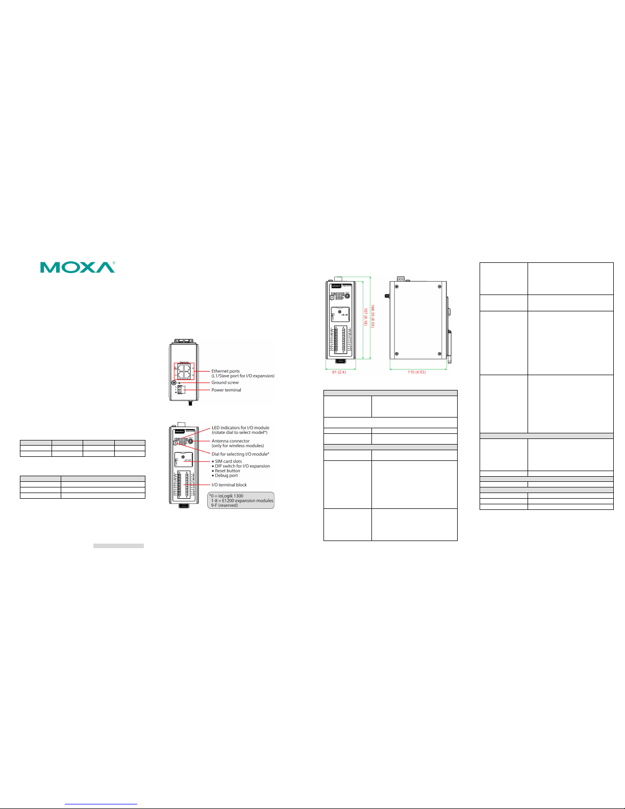
Appearance
Top View
Front View
Physical Dimensions (unit = mm/inch)
Specifications
LAN
Ethernet • 4 switched 10/100 Mbps RJ45 ports
• 1 optimized port for faster downstream
communicat ions with dais y-chained ioL ogik
E1200 units
Note: The optimized daisy-chain port is not supported on wind
industry devices (ioLogik E1261W-T, E1261H-T, or E1263H-T)
Protection
1.5 kV magnet ic isolation
Protocols Modbus/TCP, TCP/IP, UDP, DHCP, B OOTP,
SNMP, HTTP, CGI, SNTP, SMTP
WLAN (ioLogik 13xx-WL1)
Standards
• IEEE 802.11a/b/g for wireless LAN
• IEEE 802.11i for wire less security
Spread Spectrum and
Modulation (typical)
• DSSS with DBPSK, DQPSK, CCK
• OFDM with BPSK, QPSK, 16QAM, 64QAM
• 802.11b:
CCK @ 11/5.5 Mbps, DQ PSK @ 2 Mbps,
DBPSK @ 11 Mbps
• 802.11a/g:
64QAM @ 54/48 Mbps,
16QAM @ 36/24 Mbps,
QPSK @ 18/12 Mbps, BPS K @ 9/6 Mbps
Operating Channels
(central frequency)
• US:
2.412 to 2.462 GHz (11 channels)
5.18 to 5.24 GHz (4 channels)
• EU:
2.412 to 2.472 GHz (13 channels)
5.18 to 5.24 GHz (4 channels)
Security
• Firewall for MAC/IP /Protocol/Port-based
filtering
• 64-bit and 128-bit WEP encrypt ion
• Full WPA/WPA2 Person al or Enterprise
Security (IEEE802.1X /RADIUS, TKIP and
AES)
Transmission Rates • 802.11b: 1, 2, 5.5, 11 Mbps
• 802.11a/g: 6, 9, 12, 18, 24, 36, 48, 54
Mbps
TX Transmit Power • 802.11b:
Typ. 18±1.5 dBm @ 1 to 11 Mbps
• 802.11g:
Typ. 18±1.5 dBm @ 6 to 24 Mbps,
Typ. 17±1.5 dBm @ 36 Mbps,
Typ. 16±1.5 dBm @ 48 Mbps,
Typ. 16±1.5 dBm @ 54 Mbps
• 802.11a:
Typ. 18±1.5 dBm @ 6 to 24 Mbps,
Typ. 16±1.5 dBm @ 36 Mbps,
Typ. 15±1.5 dBm @ 48 Mbps,
Typ. 14±1.5 dBm @ 54 Mbps
RX Sensiti vity
• 802.11b:
-97 dBm @ 1 Mbps, -94 dBm @ 2 Mbps,
-92 dBm @ 5.5 Mbps, -
90 dBm @ 11 Mbps
• 802.11g:
-88 dBm @ 6 to 24 Mbps,
-85 dBm @ 36 Mbps, -
75 dBm @ 48 Mbps,
-70 dBm @ 54 Mbps
• 802.11a:
-88 dBm @ 6 to 24 Mbps,
-85 dBm @ 36 Mbps, -
75 dBm @ 48 Mbps,
-70 dBm @ 54 Mbps
Cellular (ioLogik 13xx-GPRS/HSPA)
Band Options
• Five-Band:
UMTS/HSPA+(WCDMA/FDD)800/850/
AWS1700/1900/2100 MHz
• Quad-band:
GSM/GPRS/EDGE 850/900/1800/1900
MHz
SIM Control Voltage
3.0 V/1.8 V
Power Requirements
Power Input
9 to 48 VDC24, VDC nominal
Physical Characteristics
Wiring
I/O cable max. 14 AWG
Dimensions
61 x 157 x 115 mm (2.4 x 6.18 x 4.53 in)
Weight
under 1.2 kg
Page 2
– 5 – – 6 – – 7 – - 8 -
www.moxa.com/support
The Americas:
+1-714-52 8-6777 (toll-free: 1-888-669-2872)
Europe:
+49 -89-3 70 03 99-0
Asia-Pacific:
+886-2-8919-1230
China:
+86 -21-5258-9955 (toll-free: 800-820-5036)
2015 Moxa Inc. All right s reserved.
Environment Limits
Operating Temperature
Standard Models:
Wide Temp. Models:
-10 to 60°C (14 to 140°F)
-30 to 70°C (-22 to 158°F)
Storage Temperature
-40 to 85°C (-40 to 185°F)
Ambient Relative
Humidity
5 to 95% (non-condensing)
Altitude
Up to 2000 m
Note: Please contact Moxa if you require products guaranteed to
function properly at higher altitudes.
Digital Input
Sensor Type
Wet Contact (NPN or PNP) and Dry Contact
I/O Mode
DI or Event Counter
Dry Contact
• On: short to GND
• Off: open
Wet Contact
(DI to COM)
• On: 10 to 30 VDC
• Off: 0 to 3 VDC
Isolation
3k VDC or 2k Vrms
Counter/Frequency
2.5 kHz
Digital Output (Sink)
I/O Mode
DO or Pulse Output
Pulse Output Frequency
5 kHz
Over-voltage Protection
45 VDC
Over-temperature
Shutdown
175°C (min.)
Over-current Protection
1.5 A per channel @ 25°C
Current Rating
500 mA per channel @ 25°C
Isolation
3k VDC or 2k Vrms
Analog Input (ioLogik 1342)
Type
Differential input
Resolution
16 bits
I/O Mode
Voltage / Current (software selectable)
Input Range ±10 V, 0 to 10 V, 0 to 20 mA, 4 to 20 mA
(with burn- out detection)
Accuracy
±0.1% FSR @ 25°C
±0.3% FSR @ -10 and 60°C
±0.5% FSR @ -40 and 75°C
Sampling Rate
• All channels: 400 samples/sec
• Per channel: 100 samples/s ec
Input Impedance
> 1M ohms (m in.)
Built-in Re sistor for
Current Input
120 ohms
Warranty
Warranty Period
5 years
Details
See www.moxa.com/warranty
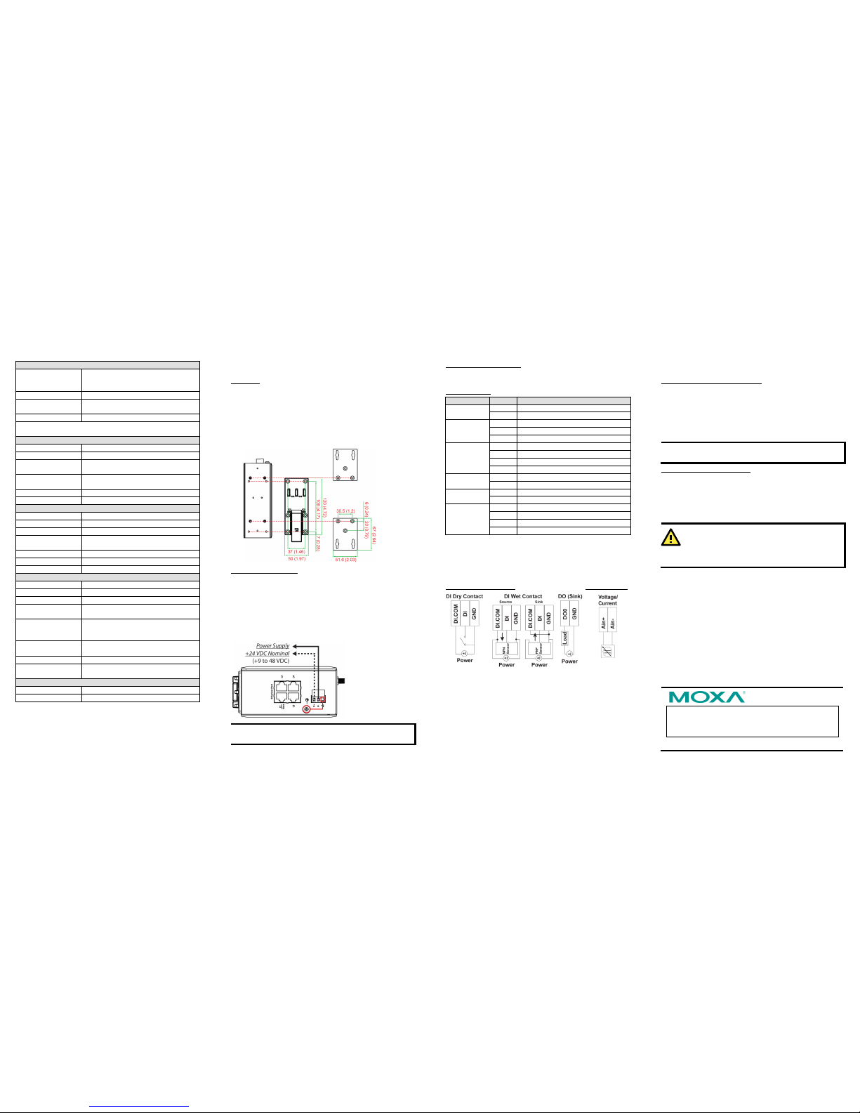
Hardware Installation
Mounting
There are two sliders on the back of the unit for DIN rail and wall
mounting.
• Mounting on a DIN rail
Pull out the bottom slider; latch the unit onto the DIN rail, and
the push the slider back in.
• Mounting on a wall (optional)
Pull out both the top and bottom sliders and align the screws
accordingl y.
Connecting the Power
Connect a 9 to 48 VDC power lin e to the ioLog ik 1300’s terminal
block V+ terminal; connect the ground from the power supply to the
V- terminal.
For most applica tions, it is desirab le to ground the syst em by
connecting the system’s po wer supply common wire to the chassis
or panel ground. The negative (–V) side of the DC power input
terminal as well as all I/O poin t terminals labeled GND should be
connected to chassis ground.
NOTE
For safety reasons, wires connecting the power supply
should be a t least 2 mm in diameter (e.g., 12 gauge wires).
Connecting to a Network
The ioLogik 1300 has four built-in RJ45 Ethernet ports for connecting
standard direct or crossover Ethernet cables.
LED Indicators
Type
Color
Description
Power
(PWR)
Green
System power is ON
Off
System power is OFF
Ready
(RDY)
Green
System ready
Red
System error
Off
System is not ready
Ethernet Port
(L1/L2/L3/L4)
Green
Ethernet connection enabled in 100 Mbps
Amber
Ethernet connection enabled in 10 Mbps
Flashing
Data transmitting
Off
Disconnected
I/O Channel
Status*
Green
Channel ON
Off
Channel OFF or No Counter/Pulse Signal
W.Link**
Green
Cellular connection established
Off
Off
Signal Status**
Off
No signal, o r No SIM card
1 LED
Weak or ins ufficient (SMS only)
2 LEDs
Average (good for cellular conn ections)
3 LEDs
Excellent s ignal
*Use the rotary switch to select which module's I/O channel status is
displayed.
**Wireless Mo dules Only
I/O Wiring
Digital Inputs/Outp uts
Analog Inputs
System Configuration
Configuration via IOxpress Utility
The configuration of the ioLogik 1300 is mainly done with the
IOxpress utility. IOxpress is a search utility that helps users locate
an ioLogik 1300 device on the local network. The utility can be found
in the Document and Software CD
Software IOxpress
folder. The latest version can be downloaded from Moxa’s website.
• Default IP Address: 192.168.127.253
• Default Subnet Mask: 255.255.255.0
NOTE Be sure to configure the host PC’s IP address to the same
subnet as the ioLogik 1300. For example, 192.168.127.253
Load Factory Default Settings
There are three ways to restore the ioLogik 1300 to factory default
settings.
1. Hold the RESET button for 5 seco nds.
2. In the IOxpress utility, right-click on the ioLogik device to be
reset and select Reset to Default.
3. Select Load Factory Default from the web console.
WARNING
This equipment is intended to be used in Restricted Access
Locations. External metal parts are hot! Before touching it,
special attention or prote ction is necessary.
 Loading...