

Moxa Technologies IMC-P101-S-ST, IMC-P101-M-SC, IMC-P101-M-SC-T, IMC-P101-M-ST-T, IMC-P101-S-SC-T Hardware Installation Manual
...Page 1

Moxa PoE Media Converter
IMC-P101
Hardware Installation Guide
First Edition, November 2009
© 2009 Moxa Inc. All rights reserved.
Reproduction without permission is prohibited.
Fl.4, No.135, Lane 235, Pao-Chiao Rd. Shing Tien City, Taipei, Taiwan,
R.O.C.
TEL: +886-2-8919-1230
P/N: 1802001015010
Page 2

- 2 -
Overview
The IMC-P101 series is an Ethernet to fiber optic media converter. It provides
Ethernet media conversion from 10/100 BaseT(X) to 100 BaseFX(SC/ST
connectors). These media converters are classified as power source equipment
(PSE), and when used in this way, the IMC-P101 series provides up to 15.4
watts to powered devices (PD). The IMC-P101 series can be used to power
IEEE 802.3af compliant powered devices (PD), eliminating the need for
additional wiring, and supports IEEE 802.3/802.3u/802.3x with 10/100M,
full/half-duplex, and MDI/MDI-X auto-sensing to provide a total solution for
your industrial Ethernet network.
The IMC-P101 Series includes the following models:
y IMC-P101-M-SC: PoE Industrial 10/100BaseT(X) to 100BaseFX media
converter, multi-mode port with SC connector, 0 to 60°C operating
temperature.
y IMC-P101-M-ST: PoE Industrial 10/100BaseT(X) to 100BaseFX media
converter, multi-mode port with ST connector, 0 to 60°C operating
temperature.
y IMC-P101-S-SC: PoE Industrial 10/100BaseT(X) to 100BaseFX media
converter, single-mode port with SC connector, 0 to 60°C operating
temperature.
y IMC-P101-S-ST: PoE Industrial 10/100BaseT(X) to 100BaseFX media
converter, single-mode port with ST connector, 0 to 60°C operating
temperature.
y IMC-P101-M-SC-T: PoE Industrial 10/100BaseT(X) to 100BaseFX media
converter, multi-mode port with SC connector, -40 to 75°C operating
temperature.
y IMC-P101-M-ST-T: PoE Industrial 10/100BaseT(X) to 100BaseFX media
converter, multi-mode port with ST connector, -40 to 75°C operating
temperature.
y IMC-P101-S-SC-T: PoE Industrial 10/100BaseT(X) to 100BaseFX media
converter, single-mode port with SC connector, -40 to 75°C operating
temperature.
y IMC-P101-S-ST-T: PoE Industrial 10/100BaseT(X) to 100BaseFX media
converter, single-mode port with ST connector, -40 to 75°C operating
temperature.
NOTE
Throughout this Hardware Installation Guide, we often use
IMC as an abbreviation for Moxa Industrial Media
Converter:
IMC = Moxa Industrial Media Converter
Page 3

- 3 -
Package Checklist
Moxa PoE Media Converter is shipped with the following items. If any of these
items is missing or damaged, please contact your customer service
representative for assistance.
y IMC-P101 series media converter.
y Hardware Installation Guide (printed).
y Warranty Card.
Features
y 10/100BaseT(X) Auto-Negotiation and Auto-MDI/MDI-X.
y IEEE 802.3af compliant PoE.
y Power failure by relay output.
y Provides up to 15.4W of power to powered devices (PD).
y Support Store-and-Forward mode and Pass Through mode.
y -40 to 75°C operating temperature range (T models).
y Redundant dual VDC power inputs.
Page 4
- 4 -
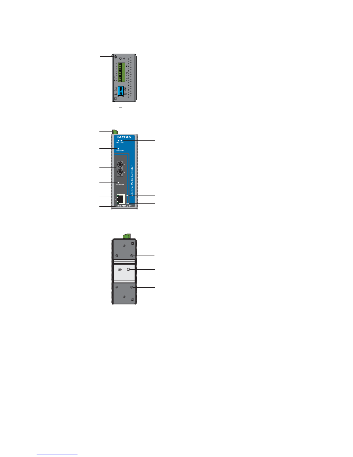
Panel Layout of the IMC-P101 Series
Top Panel View
Rear Panel View
Front Panel View (IMC-P101-M-ST)
1
2
4
3
14
15
14
2
5
7
8
9
6
12
11
10
13
1. Grounding screw
2. Terminal block for power
input PWR1/PWR2
3. Heat dissipation vents and
relay output
4. DIP switch
5. Power input PWR1 LED
6. Power input PWR2 LED
7. Fiber Link/Active LED
8. 100BaseFX (ST/SC
connector) Port
9. PSE Indicator LED
10. 10/100BaseT(X)
11. TP port 10 Mbps LED
12. TP port 100 Mbps LED
13. Model Name
14. Screw hole for wall
mounting kit
15. DIN-Rail mounting kit
Page 5
- 5 -
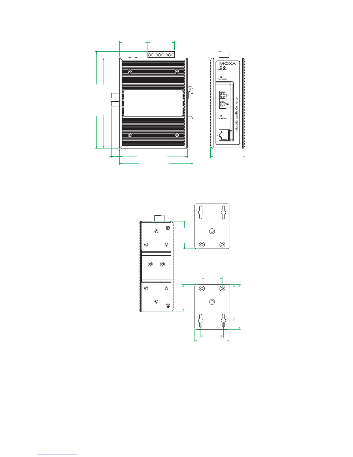
Mounting Dimensions
135.1 mm (5.32 in)
144.45 mm (5.69 in)
101.4 mm (3.99 in)
110.2 mm (4.34 in)
51.65 mm
(2.03 in)
34 mm
(1.34 in)
51.6 mm
(2.03 in)
30.5 mm
(1.2 in)
54 mm (2.13 in)
67 mm (2.64 in)
39.84 mm
(1.57 in)
40.8 mm
(1.61 in)
12.06 mm
(0.47 in)
42.4 mm
(1.67 in)
40 mm
(1.57 in)
Front ViewSide View
Rear View Panel Mounting Kit (Optional)
IMC-P101-M-SC
Page 6

- 6 -
DIN-Rail Mounting
The aluminum DIN-Rail attachment plate should be fixed to the back panel of
the IMC when you take it out of the box. If you need to reattach the DIN-Rail
attachment plate to the IMC, make sure the stiff metal spring is situated
towards the top, as shown in the figures below.
STEP 1:
Insert the top of the DIN-Rail into the
slot just below the stiff metal spring.
STEP 2:
The DIN-Rail attachment unit will
snap into place as shown below.
metal
spring
DIN-Rail
metal
spring
DIN-Rail
To remove the Moxa Industrial Media Converter from the DIN-Rail, simply
reverse Steps 1 and 2 above.
Wall Mounting (Optional)
For some applications, you will find it convenient to mount the Moxa PoE
Media Converter on the wall, as illustrated below.
STEP 1:
Remove the aluminum DIN-Rail attachment plate from the Moxa PoE Media
Converter, and then attach the wall mount plates, as shown in the diagrams
below.
⇒
Top
plate
Bottom
plate
Page 7

- 7 -
STEP 2:
Mounting the Moxa PoE Media Converter on the wall
requires 4 screws. Use the IMC, with wall mount plates
attached, as a guide to mark the correct locations of the 4
screws. The heads of the screws should be less than 6.0
mm in diameter, and the shafts should be less than 3.5
mm in diameter, as shown in the figure at the right.
NOTE
Test the screw head and shank size by inserting
the screw into one of the keyhole shaped
apertures of the Wall Mounting Plates, before it
is screwed into the wall.
Do not screw the screws in all the way—leave a space of
about 2 mm to allow room for sliding the wall mount
panel between the wall and the screws.
6.0 mm
3.5 mm
STEP 3:
Once the screws are fixed in the wall, insert the four screw heads through the
large openings of the keyhole-shaped apertures, and then slide Moxa PoE
Media Converter downwards, as indicated below. Tighten the four screws for
added stability.
Grounding the Moxa Industrial Media
Converter
Grounding and wire routing help limit the effects of noise due to
electromagnetic interference (EMI). Run the ground connection from the
ground screw to the grounding surface prior to connecting devices.
ATTENTION
This product is intended to be mounted to a well-grounded
mounting surface such as a metal panel.
Page 8

- 8 -
Wiring the Redundant Power Inputs
The top five contacts of the 8-contact terminal block connector on the IMC’s
top panel are used for the IMC’s two DC inputs. Top and front views of one of
the terminal block connectors are shown here.
Top View
Front View
STEP 1: Insert the negative/positive DC wires
into the V-/V+ terminals.
STEP 2: To keep the DC wires from pulling
loose, use a small flat-blade screwdriver to
tighten the wire-clamp screws on the front of the
terminal block connector.
STEP 3: Insert the plastic terminal block
connector prongs into the terminal block receptor,
which is located on the IMC’s top panel.
ATTENTION
Before connecting the IMC to DC power inputs, make sure
the DC power source voltage is stable.
Communication Connections
IMC-P101 models have one 10/100BaseT(X) Ethernet port, and one
100BaseFX (SC or ST type connector) fiber port.
10/100BaseT(X) Ethernet Port Connection
The 10/100BaseT(X) Ethernet port located on the IMC’s front panel is used to
connect to Ethernet-enabled devices.
Illustrated below are pinouts for both MDI (NIC-type) ports and MDI-X
(HUB/Switch-type) ports, and also cable wiring diagrams for straight-through
and cross-over Ethernet cables.
RJ45 (8-pin, MDI) Port Pinouts RJ45 (8-pin, MDI-X) Port Pinouts
1
8
Pin Signal
1
2
3
6
Tx+
TxRx+
Rx-
1
8
Pin Signal
1
2
3
6
Rx+
RxTx+
Tx-
Page 9

- 9 -
RJ45 (8-pin) to RJ45 (8-pin) Straight-Through Cable Wiring
Straight-Through Cable
RJ45 Plug Pin 1
Switch Port
RJ45
Connector
RJ45
Connecto
r
Tx+
TxRx+
Rx-
NIC Port
Cable Wiring
3 3
6 6
1 1
2 2
Rx+
RxTx+
Tx-
RJ45 (8-pin) to RJ45 (8-pin) Cross-Over Cable Wiring
Cross-Over Cable
RJ45 Plug Pin 1
Switch Port
(NIC Port)
RJ45
Connector
RJ45
Connector
Tx+
TxRx+
Rx-
(Rx+)
(Rx-)
(Tx+)
(Tx-)
(Tx+)
(Tx-)
(Rx+)
(Rx-)
Switch Port
(NIC Port)
Cable Wiring
3 1
6 2
1 3
2 6
Rx+
RxTx+
Tx-
100BaseFX Ethernet Port Connection
The concept behind the SC port and cable is quite straightforward. Suppose
you are connecting devices I and II. Unlike electrical signals, optical signals do
not require a circuit in order to transmit data. Consequently, one of the optical
lines is used to transmit data from device I to device II, and the other optical
line is used transmit data from device II to device I, for full-duplex
transmission.
All you need to remember is to connect the Tx (transmit) port of device I to the
Rx (receive) port of device II, and the Rx (receive) port of device I to the Tx
(transmit) port of device II. If you are making your own cable, we suggest
labeling the two sides of the same line with the same letter (A-to-A and B-to-B,
as shown below, or A1-to-A2 and B1-to-B2).
SC-Port Pinouts SC-Port to SC-Port Cable Wiring
Tx
Rx
AA
BB
Cable Wiring
A A
B B
ST-Port Pinouts ST-Port to ST-Port Cable Wiring
Page 10

- 10 -
Tx
Rx
AA
B
Cable Wiring
A A
B B
B
ATTENTION
This is a Class 1 Laser/LED product. Do not stare into the
Laser Beam.
Redundant Power Inputs
Both power inputs can be connected simultaneously to live DC power sources.
If one power source fails, the other live source acts as a backup, and
automatically supplies all of the Moxa Industrial Media Converter’s power
needs.
DIP Switch Setting
1234567
ON DIP
DIP No. Function ON OFF
1 Auto Negotiation Enable* Disable
“ON”: Enables “Auto Negotiation” function, the speed and duplex states for
each port link segment are automatically configured using the highest
performance interoperation mode.
“OFF”: Disables “Auto Negotiation” function, the speed and duplex states
depend on the manual setting configuration.
2 Force TP Speed 100Mbps* 10Mbps
(Only when Auto Negotiation is disabled)
“ON”: Forces 100Mbps on Ethernet port.
“OFF”: Forces 10Mbps on Ethernet port.
3 Force TP Duplex Full Duplex* Half Duplex
(Only when Auto Negotiation is disabled)
“ON”: Forces Full Duplex on Ethernet port.
“OFF”: Forces Half Duplex on Ethernet port.
4 Link Fault Pass Through Enable* Disable
“ON”: Enables “Link Fault Pass Through”, the link status on the TX port will
inform the FX port of the same device and vice versa.
“OFF”: Disables “Link Fault Pass Through”, the link status on the TX port
will not inform the FX port.
5 Operating Mode Store-and-Forward* Pass Through
Page 11

- 11 -
DIP No. Function ON OFF
“ON”: Selects “Store-and-Forward” mode, begins to forward a packet to a
destination port after an entire packet is received. The latency depends
on the packet length.
“OFF”: Selects “Pass Through” mode, operates with the minimum latency.
Both transceivers are interconnected via internal MIIs and the
internal switch engine and data buffer are not used.
Note: With “Pass Through” mode enabled, the Ethernet port and fiber port
should transmit at 100 Mbps, which is equivalent to full duplex mode.
6 PSE Disable Enable*
PSE: Power Source Equipment.
“ON”: Disables “PSE”, IMC-P101 series do NOT provide power to PD
(Powered Device).
“OFF”: Enables “PSE”, IMC-P101 series provides power to PD (Powered
Device).
7 P.R.R. Enable Disable*
P.R.R.: Power Remote Reset
“ON”: Enables “P.R.R” function, when fiber port link down 3 seconds and
“PSE” setting is enabled, IMC-P101 series STOP providing power to
PD (Power Device) which means the PD power will turn OFF. After 1
second later, IMC-P101 series start to continue provide power to PD,
and then the PD power turn back ON for reset PD.
“OFF”: Disables “P.R.R” function, no reset PD function.
(*): Default DIP switch setting.
ATTENTION
After changing the DIP switch setting, you will need to
power off and then power on the IMC-P101 to activate the
new setting.
LED Indicators
The front panel of Moxa Industrial Media Converter contains several LED
indicators. The function of each LED is described in the table below.
LED Color State Description
ON
Power is being supplied to power input
PWR1
PWR1 Green
OFF
Power is not being supplied to power
input PWR1
ON
Power is being supplied to power input
PWR2
PWR2 Green
OFF
Power is not being supplied to power
input PWR2
ON Fiber port is active.
Blinking Data is being transmitted or received.
Fiber
Link/Act
Green
OFF Fiber port is inactive.
ON PSE is enabled.
1 Flash Low Signature Resistance
PSE
Indicator
Green
2 Flash High Signature Resistance
Page 12

- 12 -
5 Flash Power overload Fault
9 Flash Power Management Allocation Exceeded
ON Ethernet port 10 Mbps link is active.
Blinking Data is being transmitted at 10 Mbps.
10M Yellow
OFF Ethernet port 10 Mbps link is inactive.
ON Ethernet port 100 Mbps link is active.
Blinking Data is being transmitted at 100 Mbps.
100M Green
OFF Ethernet port 100 Mbps link is inactive.
Specifications
Technology
Standards
IEEE 802.3 for 10BaseT,
IEEE 802.3u for 100BaseT(X), 100BaseFX
IEEE 802.3af for Power-over-Ethernet
Interface
RJ45 ports 10/100BaseT(X)
Fiber ports 100BaseFX (SC, ST connectors available)
LED Indicators
PWR1, PWR2, Fiber Link/Act, 10/100M (Ethernet
port), PSE Indicator
DIP Switches:
Dip No. Function ON OFF
1 Auto Negotiation Enable* Disable
2 Force TP Speed 100Mbps* 10Mbps
3 Force TP Duplex Full Duplex* Half Duplex
4 Link Fault Pass Through Enable* Disable
5 Operating Mode Store-and-Forward* Pass Through
6 PSE Disable Enable*
7
P.R.R.
(PD Remote Reset)
Enable Disable*
(*): Default DIP switch setting.
Alarm Contact
One relay output with current carrying capacity
of 1A @ 24 VDC
Optical Fiber
100BaseFX
Multi-mode Single-mode
Wavelength 1300 nm 1310 nm
Max. TX -10 dBm 0 dBm
Min. TX -20 dBm -5 dBm
RX Sensitivity -32 dBm -34 dBm
Link Budget 12 dB 29 dB
Typical Distance
5 km
a
4 km
b
40 km
c
Saturation -6 dBm -3 dBm
Page 13

- 13 -
a. 50/125 μm, 800 MHz*km fiber optic cable
b. 62.5/125 μm, 500 MHz*km fiber optic cable
c. 9/125 μm, 3.5 PS/(nm*km) fiber optic cable
Physical Characteristics
Housing Metal
Dimensions (W x H x D)
144.45 x 110.2 x 51.65 mm (5.69 x 4.34 x 2.03
in)
Weight Product only: 525g
Packaged: 710g
Installation
DIN-Rail mounting, Wall Mounting (optional
kit)
Environmental Limits
Operating Temperature
Standard Models: 0 to 60
o
C (32 to 140 oF)
Wide Temp. Models: -40 to 75
o
C (-40 to 167 oF)
Storage Temperature -40 to 85
o
C (-40 to 185 oF)
Ambient Relative
Humidity
5 to 90% (non-condensing)
Power Requirements
Input Voltage 48VDC (46 to 57 VDC), redundant inputs
Power Consumption 430mA@48VDC (max.)
Connection Removable terminal block
Overload Current Protection
1.6 A (protects against two signals shorted
together)
Reverse Polarity Protection Present
Regulatory Approvals
Safety UL508
EMI FCC Part 15, CISPR (EN55022) class A
EMS IEC 61000-4-2 Edition 1.2: 2001-04(Level 4)
EN 61000-3-3: 1995 + A1: 2001
IEC 61000-4-3: 2002+A1: 2002(Level 3)
IEC 61000-4-4: 2004(Level 4)
IEC 61000-4-5 Edition 1.1: 2001-04(Level 3)
IEC 61000-4-6 Edition 2.1: 2004-11(Level 3)
IEC 61000-4-8 Edition 1.1: 2001-03(Level 3)
IEC 61000-4-11 Second Edition: 2004-03
Shock IEC 60068-2-27
Free Fall IEC 60068-2-32
Vibration IEC 60068-2-6
Warranty
Warranty Period
5 years
Details: See www.moxa.com/warranty
Page 14

- 14 -
Technical Support Contact Information
www.moxa.com/support
Moxa Americas:
Toll-free: 1-888-669-2872
Tel: +1-714-528-6777
Fax: +1-714-528-6778
Moxa China (Shanghai office):
Toll-free: 800-820-5036
Tel: +86-21-5258-9955
Fax: +86-10-6872-3958
Moxa Europe:
Tel: +49-89-3 70 03 99-0
Fax: +49-89-3 70 03 99-99
Moxa Asia-Pacific:
Tel: +886-2-8919-1230
Fax: +886-2-8919-1231
 Loading...