

Page 1

P/N: 1802001014017
*1802001014017*
IMC-101G Series
Quick Installation Guide
Moxa Industrial Media Converter
Edition 7.0, February 2017
Technical Support Contact Information
www.moxa.com/support
Moxa Americas:
Toll
-free: 1-888-669-2872
Tel:
1-714-528-6777
Fax:
1-714-528-6778
Moxa China (Shanghai office):
Toll
-free: 800-820-5036
Tel:
+86-21-5258-9955
Fax:
+86-21-5258-5505
Moxa Europe:
Tel:
+49-89-3 70 03 99-0
Fax:
+49-89-3 70 03 99-99
Moxa Asia-Pacific:
Tel:
+886-2-8919-1230
Fax:
+886-2-8919-1231
Moxa India:
Tel:
+91-80-4172-9088
Fax:
+91-80-4132-1045
2017 Moxa Inc. All rights reserved.
Page 2

- 2 -
Overview
Moxa’s IMC-101G industrial gigabit media converter is designed for
reliable and stable operations in harsh industrial environments, and it
provides industrial-grade media conversion between
10/100/1000BaseT(X) and 1000BaseSX/LSX/LX/LH/LHX/ZX/EZX (SFP
Slot) connections. The IMC-101G’s reliable industrial design is excellent
for keeping your industrial automation app lications running continuo usly,
and it comes with an alarm that activates a relay output to help prevent
damage.
This product has a wide operating temperature range of -40 to 75°C and
is designed to withstand a high de gree of vibration and shock. The rugged
hardware design makes the IMC-101G perfect for ensuring that your
Ethernet equipm ent can withstand a variety of application env ironments,
such as hazardous locations (Class 1 Division 2/Zone 2, IECEx), and
complies with CE, FCC, and UL Standards
Package Checklist
The IMC-101G industrial media converter is shipped with the items listed
below. If any of these items is missing or damaged, please contact your
customer service representative for assistance.
• Moxa industrial media converter
• Quick installation guide (printed)
• Warranty card
Features
• Supports 10/100/1000BaseT(X) auto-negotiation, auto-MDI/MDI-X,
with 1000BaseSX/LSX/LX/LH/LHX/ZX/EZX SFP available
• Supports Link Fault Pass-through
• Relay Output alarm for when a port breaks or the power fails
• Redundant 12 to 45 VDC power inputs
• DIN rail and panel mountable
• Standard operating temperature range of 0 to 60°C, or extended
operating temperature range of -40 to 75°C for -T models
Page 3
- 3 -
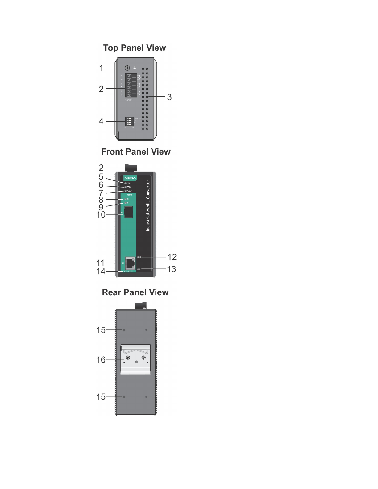
Panel Layouts of the IMC-101G Series
1.
Grounding screw
2. Terminal block for power inputs
(PWR1/PWR2) and relay output
3.
Heat dissipation vents
4.
Dip switches
5.
Power input PWR1 LED
6.
Power input PWR2 LED
7.
Fault LED
8.
SFP port’s 1000 Mpbs G2 LED
9.
TP port’s 1000 Mpbs G1 LED
10.
1000BaseSFP fiber port
11.
10/100/1000BaseT(X) port
12.
TP port’s 100 Mbps LED
13.
TP port’s 10 Mbps LED
14.
Model name
15.
Screw hole for wall-mounting
kit
16.
DIN-rail mounting kit
Page 4
- 4 -
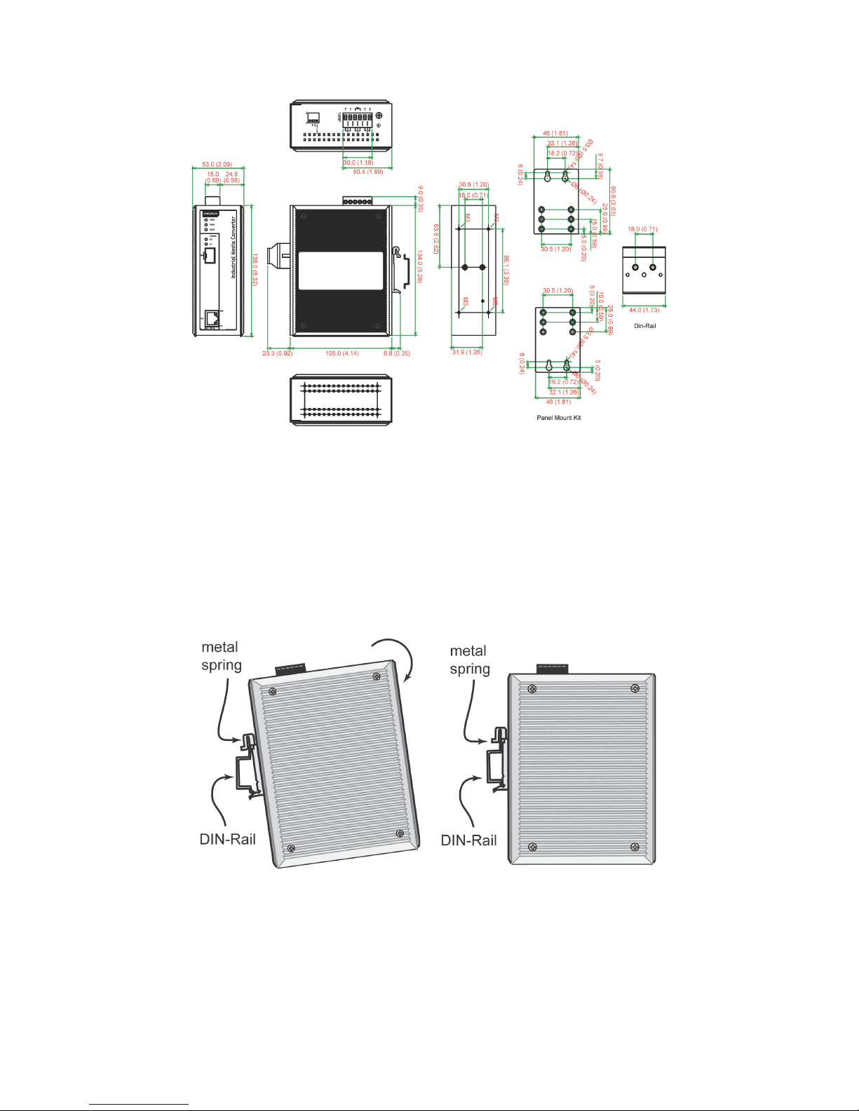
Dimensions; unit = mm (inch)
DIN-Rail Mounting
The aluminum DIN-rail attachment plate should be fixed to the back panel
of the IMC-101G when you take it out of the box. If you nee d to reattach
the DIN-rail attachment plate to the IMC-101G, make sure the stiff metal
spring is situated towards the top, as shown in t h e figures below.
STEP 1:
Insert the top of the DIN
rail into
the slot just below
the stiff metal
spring.
STEP 2:
The DIN
-rail attachment unit will
snap into place as shown below.
To remove the IMC-101G from the DIN ra il, reverse steps 1 and 2 above.
Page 5

- 5 -
Wall Mounting (Optional)
For some applications, you will find it conv enient to mount the IMC-101G
on the wall, as illustrated below.
STEP 1:
Remove the aluminum
DIN
-rail attachment plate
from
the IMC-101G and
then attach the wall-mount
plates, as shown in the
diagrams below.
STEP 2:
Mounting
the IMC-101G on the wall requires four
screws. Use the IMC
-101G, with wall-mount plates
attached, as a guide to mark the correct loca tions of
the
four
screws. The heads of the screws sho uld be less
than 6.0 mm in diameter, and the shafts should be less
than 3.5 mm in diameter, as shown in the figure
on
the
right.
NOTE
Test the screw head and shank size by inserting the screw into
one of the keyhole
-shaped apertures of the wall-
mounting plates,
before it is screwed into the wall.
Do not screw the screws in all the way—leave a space of about 2 mm to
allow room for sliding the wall-mount panel between the wall and the
screws.
STEP 3:
Once the screws are fixed in the wall,
insert the four screw heads through
the
large parts of the
keyhole-shaped apertures and then
slide
the IMC-101G downwards, as
indicated
in the diagram
. Tighten the
four screws for added stability.
Page 6

- 6 -
ATEX and IECEx Information
1. Certification number
DEMKO 09 ATEX0812123X
IECEx: IECEx UL 13.0046X
2.
Ambient range:
(-40°C ≤ T
amb
≤ 75°C)
3.
Certification string
ATEX: Ex nA nC IIC T4 Gc
IECEx: Ex nA nC IIC T4 Gc
4.
Standards covered:
EN 60079-0: 2012:+A11:2013/
IEC 60079-0:Ed 6.0
EN 60079-15: 2010/
IEC 60079-15:Ed 4.0
II 3G
DEMKO
09 ATEX
0812123X
Ex nA nC IIC T4 Gc
Ambient Range
:
-40°C ≦ T
amb
≦ +75°C
Rated Cable Temp
≧ 93°C
FI.4, No.135, Lane 235, Baoqiao
Rd. Xindia n Diist. , New Taip ei City,
Taiwan
5. Conditions of safe usage:
The Ethernet Communication Devices are only to be mounted in an
ATEX/ IECEx-certified tool-accessible IP54 enclosure and used in an
area of not more than pollution degree 2 as defined by IEC/EN
60664-1.
Provisions shall be made, either in the equipment or external to the
equipment, to provide the transient protection device to be set at a
level not exceeding 140% of the peak rated voltage.
6. Additional use guide:
The conductor used for grounding is the same size as power
conductors. The temperature rating of input conductors shall be
higher than 92°C.The Terminal Block is suitable for 12-28 AWG
(3.31–0.08 mm²), torque value 4.5 lb-in.
Wiring Requirements
WARNING
Do not disconnect modules or wires unless
the power has been
switched off
or the area is known to be nonhazardous. The
devices may only be connected to the supply vo ltage shown on
the type plate.
These devices must be supplied by a SELV source as defined in
the Low Voltage Directive 2006/95/EC.
ATTENTION
This unit is a built
-in type. It must comply with fire enclosure
stipulations of IEC60950
-1/EN60950-1, or similar statements,
when installed in certain end equipment.
Page 7

- 7 -
ATTENTION
Safety First!
Calculate the maximum possible current in each power wire and
common wire. Observe all electrical codes dictating the
maximum
allowed current
for each wire size. If the current goes
above the
allowed maximum
, the wiring could overheat, causing
serious damage to your equipment.
You should also pay attention to the following points:
• Use separate paths to route wiring for power and devices. If power
wiring and device wiring paths must cross, make sure the wires a re
perpendicular at the point of intersection.
NOTE: Do not run signal or communicat ions wiring and power wiring
in the same wire conduit. To avoid interference, w ires with different
signal characteristics should be routed separately.
• You can use the type of signal transmitted thro u gh a wire to
determine which wires should be kept separate. The rule of thumb is
that wiring that shares similar electrical characteristics can be
bundled together.
• Keep input wiring and output wiring separate.
• It is strongly advised that you label wiring to all devices in the system
when necessary.
Grounding the IMC-101G
Grounding and wire routing help limit the effects of noise due to
electromagnetic interference (EMI). Run the groun d connect ion from th e
grounding screw to the grounding surface before connecting devices.
ATTENTION
This product is intended to be mounted to a well
-grounded
mounting surface such as a metal panel.
WARNING
HOT SURFACE
, DO NOT TOUCH!! Before touching the surface,
make sure it has cooled sufficiently so as not
to damage your
skin, or wear gloves designed to protect against heat.
This equipment is intended to be used in a Restricted Acc ess Location that
is only accessible by SERVICE PERSONNEL or by USERS who have been
instructed that the metal chassis of the equipment is so hot that
appropriate precautions should be taken before touch ing it. The
Restricted Access Location should only be accessib le through t he use of a
key or security identity system.
Page 8

- 8 -
Wiring the Alarm Contact
The Alarm Contact is made up of the two middle contacts of the terminal
block on the IMC-101G’s top panel. Refer to the next section for detailed
instructions on how to connect the wires to the terminal block connector
and how to attach the terminal block connector to the terminal block
receptor.
In this section, we explain the meaning of the two contacts used to
connect the alarm contact.
FAULT: The two middle contacts of the
6
-contact terminal block connector are
used to
detect both power faults and port faults. The
two wires attached to the
fault contacts form
an open circuit when
:
1.
The IMC-101G
has lost power from one of
the DC power inputs.
OR
2.
One of the ports for which the
corresponding PORT ALARM DIP Swit
ch is
set to ON is not properly connected.
If neither of these two conditions
is met, the
f
ault circuit will be closed.
Wiring the Redundant Power Inputs
The top two contacts and the bottom two contacts of the 6-contact
terminal block connector on the IMC-101G’s top panel are used for the
IMC-101G’s two DC inputs. The top and front views of one of the t erminal
block connectors are shown here.
STEP 1:
Insert the negative/positive DC wires into the
V
-/V+ terminals, respectively.
STEP 2:
To keep the DC w ires from pulling loose, use a
small flat
-blade screwdriver to tighten the
wire-clamp screws on the front of the termina l
block connector.
STEP 3:
Insert the plastic terminal block
connector
prongs into the terminal block receptor, which
is located on the
IMC-101G’s top panel.
NOTE
Use copper conduct ors only; 12-28 AWG gauge, 4.5 in-lb torque.
ATTENTION
Before connecting the IMC
-101G
to the DC power inputs, make
sure the DC power source voltage is stable.
Page 9

- 9 -
Communication Connections
All IMC-101G models have one 10/100/1000BaseT(X) Ethernet port and
one 1000Base SFP fiber port.
10/100/1000BaseT(X) Ethernet Port Connection
The 10/100/1000BaseT(X) ports located on the IMC-101G’s front panel
are used to connect to Ethernet-enabled devic es. Below we show pinout s
for both MDI (NIC-type) ports and MDI-X (HUB/switch-type) ports, and
also show cable wiring diagrams for straight-through and crossover
Ethernet cables.
10/100Base T(x) RJ45 Pinouts
MDI Port Pinouts
MDI-X Port Pinouts
8-pin RJ45
Pin
Signal
1
Tx+
2
Tx-
3
Rx+
6
Rx-
Pin
Signal
1
Rx+
2
Rx-
3
Tx+
6
Tx-
RJ45 (8-pin) to RJ45 (8-pin) Straight-Through Cable Wiring
RJ45 (8-pin) to RJ45 (8-p in) Crossover Cable Wiring
Page 10

- 10 -
1000BaseT(X) Ethernet Port Connection
1000BaseT(X) data is transmitted on differential TRD+/- signal pairs over
copper wires.
MDI/MDI-X Port Pinouts
Pin
Signal
1
TRD (0) +
2
TRD (0) -
3
TRD (1) +
4
TRD (2) +
5
TRD (2) -
6
TRD (1) -
7
TRD (3) +
8
TRD (3) -
1000BaseSFP Fiber Port
The gigabit Ethernet ports on the IMC-101G are 1000BaseSFP fiber ports,
which require using gigabit mini-GBIC fiber tran sceivers to work properly.
The concept behind the LC port and cable is quite straightforward.
Suppose you are connecting devices I and II: Contrary to electrical
signals, optical signals do not require a circuit in order to transmit data.
Consequently, one of the optical lines is used to transmit data from d evice
I to device II, and the other optical line is used to transmit data from
device II to device I, for full-duplex transmission.
Remember to connect the Tx (tra nsmit) port of device I to the Rx (r eceive)
port of device II, and the Rx (receive) port of device I to the Tx (transmit)
port of device II. If you make your own cable , we suggest labeling the two
sides of the same line with the same letter (A-to-A and B-to-B, as shown
below, or A1-to-A2 and B1-to-B2).
LC-Port Pinouts
LC-Port to LC-Port Cable Wiring
Optical transc eiv ers installed in the field should be UL certified, Class I
category, with a clearly visible CDRH certification marking on the
transceiver equivalent to: “Complies with 21CFR 1040.10 and 1040.11”.
Redundant Power Inputs
Both power inputs can be connected simultaneously to live DC power
sources. If one power source fails, the oth er live source act s as a back up
and automatically supplies all of the IMC-101G’s power needs.
Page 11

- 11 -
Alarm Contact
The IMC-101G has one alarm contact located on the top panel. For
detailed instructions on how to connect t he alarm contact power w ires to
the two middle contacts of the 6-contact terminal block connector, see
the “Wiring the Alarm Contact” section above. A typ ical scenario would be
to connect the fault circuit to a warning light located in the control room.
The light can be configured to switch on when a fault is detected.
The alarm contact has two terminals that form a fault circuit for
connecting to an alarm system. The two wires att ached to the fault
contacts form an open circuit when (1) the IMC-101G has lost power from
one of the DC power inputs, or (2) one of the TP/SFP ports for which the
corresponding PORT ALARM DIP Switch is set to ON is not properly
connected. If neither of these two conditions occurs, the fault circuit will
be closed.
IMC-101G DIP Switch Setting
NOTE
To activate updated DIP switch settings, power off and then
power on the IMC-101G.
Dip Switch 1
(Default: Off)
On:
Enables the PORT ALARM. If the product
experiences a power failure, or the Ethernet port
link fails,
the relay will form an open circuit and the
fault LED will light up.
Off:
Disables the corresponding PORT ALARM. The
relay will form a closed circuit and the f
ault LED will
never light up.
Dip Switch 2
(Default: On)
On: Enables LFP (Link Fault Pass-through). To enable
the IMC-101 for LFP, set the SFP port to Auto
mode.
Off:
Disables LFP (Link Fault Pass-through)
Dip Switch 3
(Default: On)
On:
SFP port in Auto (auto-negotiation) mode
Off:
Forces SFP port to 1000M
Dip Switch 4
Reserved for future use
ATTENTION
When Force mode is used, the LFP function will be disabled.
Page 12

- 12 -
LED Indicators
The front panel of the IMC-101G has several LED indicators. The function
of each LED is described in the table below.
LED
Color
State
Description
PWR1 Amber
On
Power is being supplied to power input PWR1
Off
Power is not being supp lied to power input PWR1
PWR2 Amber
On
Power is being supplied to power input PWR2
Off
Power is not being supp lied to power input PWR2
FAUL
T
Red
On
When the corresponding PORT alarm is enabled
and the port’s link is inactive.
Off
When the corresponding PORT alarm is enabled
and the port’s link is active, or when the
corresponding PORT alarm is disabled.
G2 Green
On
SFP port’s 1000 Mbps link is active.
Blinking
Data is being transmitted at 1000 Mbps.
Off
SFP port’s 1000 Mbps link is inactive.
G1 Green
On
TP port’s 1000 Mbps link is active
Blinking
Data is being transmitted at 1000 Mbps
Off
TP port’s 1000 Mbps link is inactive
10M Green
On
TP port’s 10 Mbps link is active
Blinking
Data is being transmitted at 10 Mbps
Off
TP port’s 10 Mbps link is inactive
100M Green
On
TP port’s 100 Mbps link is active
Blinking
Data is being transmitted at 100 Mbps
Off
TP port’s 100 Mbps link is inactive
Auto MDI/MDI-X Connection
The Auto MDI/MDI-X function allows users to connect the IMC-101G’s
10/100/1000BaseT(X) ports to any kind of Ethernet device, without
paying attention to the type of Ethernet cable being used for the
connection. This means that you can use either a straight-through cable
or crossover cable to connect the IMC-101G to Eth erne t devices.
Dual-Speed Functionality and Switching
The IMC-101G’s 10/100/1000 Mbps RJ45 switched port auto negotiates
with the connected device for the fastest data transmission rate
supported by both devices. All mo dels of the IMC-101G are plug-and-play
devices, so that software configuration is not required at installation, or
during maintenance. The half-duplex or full-duplex mode for the RJ45
switched ports is user dependent and chang es (by auto-negotiation) to
full-duplex or half-duplex, depending on which transmission speed is
supported by the attached device.
Auto-Negotiation and Speed Sensing
All of the IMC-101G’s RJ45 Ethernet ports independently support
auto-negotiation for transmission speeds of 10 Mbps, 100 Mbps , and
1000 Mbps, with operation according to the IEEE 802.3u standard.
This means that some nodes could be operating at 10 Mbps, while at th e
same time, other nodes are operating at 100 Mbps or 1000 Mbps.
Page 13

- 13 -
Auto-negotiation takes place when an RJ45 cable connection is made.
Each time a LINK is enabled, the IMC-101G advertises its capability for
using 10 Mbps, 100 Mbps, or 1000 Mbps transmission speeds, with the
device at the other end of the cable e xpected to advertise similarly.
Depending on what type of device is connected, thi s will result in
agreement to operate at a speed of 10 Mbps, 100 Mbps, or 1000 Mbps.
If an IMC-101G’s RJ45 Ethernet port is connected to a non-negotiating
device, it will default to 10 M bps speed and half-duplex mod e, as required
by the IEEE 802.3u standard.
Specifications
Technology
Standards
IEEE802.3, 802.3u, 802.3x, 802.3z/ab, Link Fault
Pass-through
Interface
RJ45 Ports 10/100/1000BaseT(X) auto-negotiation speed, F/H
duplex mode, and auto MDI/MDI-X connection
SFP Ports
1000Base SFP slot
LED Indicators
PWR1, PWR2, FAULT, 10/100M(TP port), 1000M (TP and
SFP port)
DIP Switches
Port break alarm mask, Link Fault Pass-through, SFP
AN/Force
Alarm Contact
One relay output with current-carrying capacity of 1 A @
24 VDC, resistive
Optical Fiber: 1000BaseSX/LSX/LX/LH/LHX/ZX/EZX
(Supports SFP-1G Series module only)
Gigabit Ethernet
Wavelength
Max Tx
(dBm)
Min Tx
(dBm)
Rx Sensitivity
(dBm)
Link Budget
(dB)
Typical
Distance
Saturation
(dBm)
SFP-SX 850 nm -4 -9.5 -18 8.5 550 ma 0
SFP-LSX 1310 nm -1 -9 -19 10 2 kmb -3
SFP-LX 1310 nm -3 -9.5 -20 10.5 10 kmc -3
SFP-LH 1310 nm -2 -8 -23 15 30 kmc -3
SFP-LHX 1310 nm 1 -4 -24 20 40 kmc -3
SFP-ZX 1550 nm 5 0 -24 24 80 kmc -3
SFP-EZX 1550 nm 5 0 -30 30 110 km
c
-3
SFP-EZX120
1550 nm 3 -2 -33 31 120 km
c
-8
SFP-10A
TX 1310 nm,
RX 1550 nm
-3 -9 -21 12 10 kmc -1
SFP-10B
TX 1550 nm,
RX 1310 nm
SFP-20A
TX 1310 nm,
RX 1550 nm
-2 -8 -23 15 20 kmc -1
SFP-20B
TX 1550 nm,
RX 1310 nm
SFP-40A
TX 1310 nm,
RX 1550 nm
2 -3 -23 20 40 kmc -1
SFP-40B
TX 1550 nm,
RX 1310 nm
a. 50/125 μm, 400 MHz * km or 62.5/125 μm, 500 MHz * km @ 850 nm multimode fiber optic cable
b. 62.5/125 μm, 750 MHz * km @ 1310 nm multi-mode fiber optic cable
c. 9/125 μm single-mode fiber optic cable
Page 14

- 14 -
NOTE
The actual communication distance depen ds on ma ny factors,
including connector loss, cable deployment, an d t he age of the
cabling system. We recommend doing a link budg et analysis and
reserving a 3 dB margin for such factors.
NOTE
Please refer to the S FP-1G Series datasheet for more detailed SFP
module specifications.
Power
Input Voltage
12 to 48 VDC, Class 2, redundant inputs
Input Current
0.229 to 0.068 A
Connection
Removable Terminal Block
Overload Current
Protection
2.5 A @ 25°C
Reverse Polarity
Protection
Supported
Mechanical
Casing
Metal, IP30 protection
Dimensions (W x H x D)
53 x 135 x 105 mm (2.1 x 5.3 x 4.1 in)
Weight
630 g
Installation
DIN-rail or wall mounting (optional kit)
Environmental Limits
Operating Temperature
0 to 60°C (32 to 140°F),
-40 to 75°C (-40 to 167°F) for -T models
Storage Temperature
-40 to 85°C (-40 to 185°F)
Ambient Relative
Humidity
5 to 95% (non-condensing)
Regulatory Approvals
Safety
UL 508 (can be used in Pollution Degree 2
Environments)
EMI
FCC Part 15, CISPR 32 class A
EMS
EN61000-4-2 (ESD), Level 3
EN61000-4-3 (RS), Level 3
EN61000-4-4 (EFT), Level 3
EN61000-4-5 (Surge), Level 2
EN61000-4-6 (CS), Level 3
Shock
IEC 60068-2-27
Freefall
IEC 60068-2-32
Vibration
IEC 60068-2-6
WARRANTY
5 years
 Loading...