

Moxa Technologies IKS-6728A-8PoE, IKS-6728-8PoE-4GTXSFP-48-48-T, IKS-6728-8PoE-4GTXSFP-HV-HV-T, IKS-6728-8PoE-4GTXSFP-HV-T, IKS-6728-8PoE-4GTXSFP-48-T Hardware Installation Manual
...Page 1

2014 Moxa Inc. All rights reserved.
P/N: 1802067000010
IKS-6700A and
IKS-6728A-8PoE Series
Hardware Installation Guide
First Edition, September 2014
Page 2
- 2 -
Package Checklist
The Moxa IKS-6700A/IKS-6728A-8PoE industrial rackmount switch is
shipped with the following items. If any of these items are missing or
damaged, please contact your customer service representative for
assistance.
• IKS-6700A/IKS-6728A-8PoE switch
• USB cable (Type A male to Type B male)
• Protective caps for unused ports
• 2 rackmount ears
• Documentation and software CD
• Hardware installation guide
• CD-ROM with user's manual and SNMP MIB file
• Moxa product warranty statement
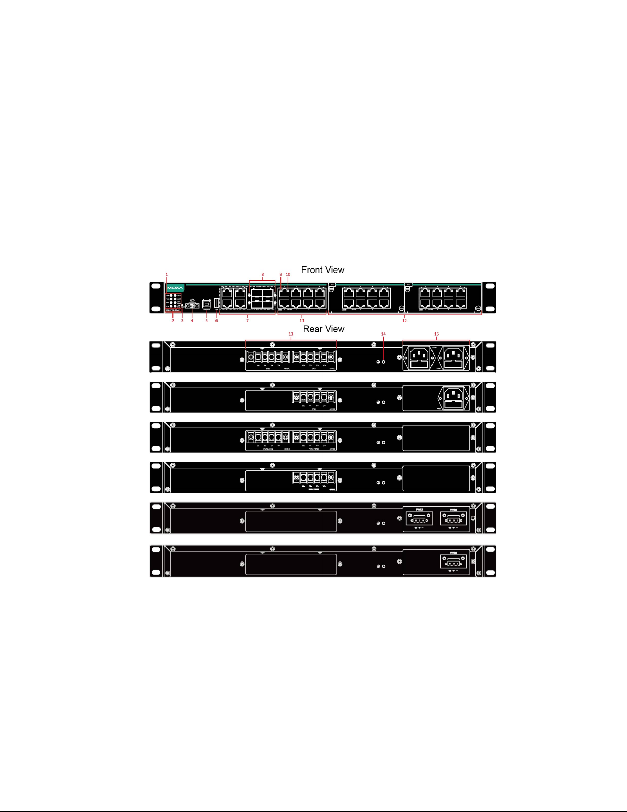
Panel Layouts
1. System status LEDs
2. Model name
3. Reset button
4. Terminal block for relay output
5. USB serial console port
6. USB storage port (ABC-02-USB-T)
7. 10/100/1000BaseT(X) or 100/1000Base SFP combo ports
8. 100/1000Base SFP port status LEDs
9. PoE+ status LEDs (IKS-6728A-8PoE series only)
10. 10/100BaseT(X) port status LEDs
11. Fast Ethernet or PoE+ interface ports
12. Fast Ethernet or PoE+ interface modules
13. Terminal blocks for DC power inputs
Page 3
- 3 -
14. Grounding screw
15. Power sockets for AC power inputs or terminal blocks for DC power
inputs
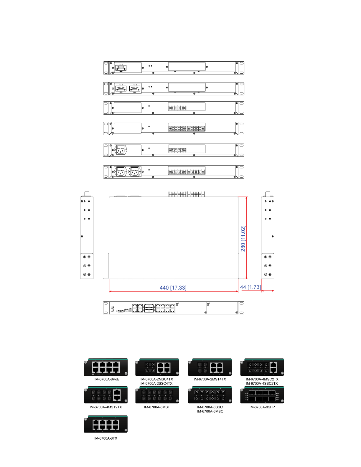
Dimensions
Unit = mm (inch)
Fast Ethernet Interface Modules (IM-6700A
Series)
Page 4

- 4 -
Grounding the Moxa Industrial Rackmount Switch
Grounding and wire routing help limit the effects of noise due to
electromagnetic interference (EMI). Run the ground connection from the
ground screw to the grounding surface prior to connecting devices.
NOTE
Using a shielded cable achieves better electromagnetic
compatibility.
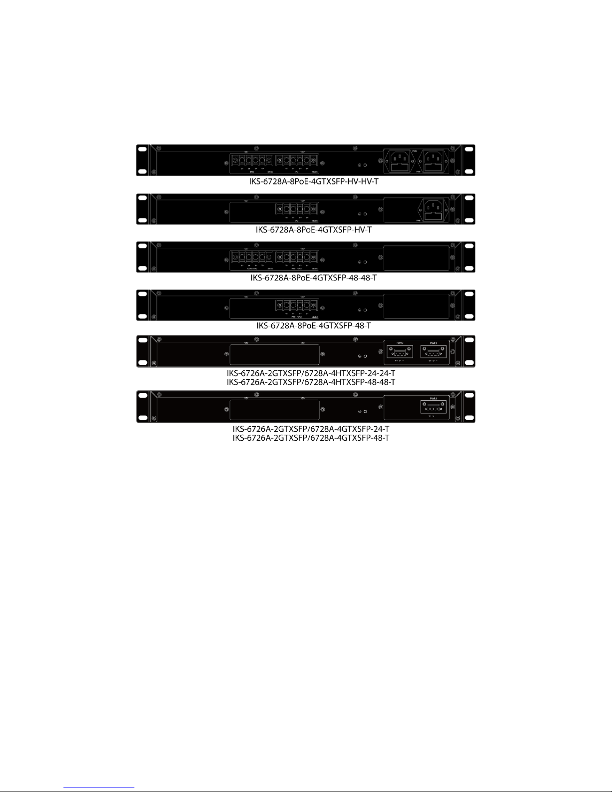
Connecting the Power Inputs
The IKS-6728A-8PoE switches support 4 types of power supply.
• IKS-6728A-8PoE-4GTXSFP-HV-HV-T: Two isolated 110/220 VAC (85
to 264 VAC) power supplies for switch and two isolated 48 VDC power
inputs for PoE+ ports
• IKS-6728A-8PoE-4GTXSFP-HV-T: One isolated 110/220 VAC (85 to
264 VAC) power supply for the switch and one isolated 48 VDC power
input for the PoE+ ports
• IKS-6728A-8PoE-4GTXSFP-48-48-T: Two isolated 48 VDC power
supplies for switch and PoE+ ports
• IKS-6728A-8PoE-4GTXSFP-48-T: One isolated 48 VDC power supply
for switch and PoE+ ports
For the HV models, the 110/220 VAC power supplies provide power for
switch operation. Separate 48 VDC power supplies are required to provide
power to all PoE+ ports (50 to 57 VDC is recommended for IEEE 802.3at
devices).
For the 48 VDC models, the 48 VDC power supplies provide power for
switch operation and to all PoE+ ports (50 to 57 VDC is recommended for
IEEE 802.3at devices).
The IKS-6700A switches support 3 types of power supply:
• IKS-6726A/6728A HV series: Two isolated 110/220VAC (85 to 264
VAC) power supplies for switch
• IKS-6726A/6728A 24/48VDC series: Two isolated 24 or 48VDC power
supplies for switch
Wiring Requirements
WARNING
Do not disconnect modules or wires unless power has been
switched off or the
area is known to be non-hazardous. The
device may only be connected to the supply voltage shown on the
type plate. The device is designed for operation with a Safety
Extra
-Low Voltage (SELV) or an isolated power supply, which
means that they may only be co
nnected to the supply voltage
connections and to the signal contact with a SELV or an isolated
power supply in compliance with IEC 60950
-1/EN 60950-
1 or UL
508.
AC Power Inlets
The connection for PWR1 (power supply 1) and PWR2 (power supply 2)
are located on the rear panel (shown below). Be sure to use a standard
Page 5
- 5 -
power cord with an IEC C13 connector, which is compatible with the AC
power inlet.
DC Power Terminal Blocks
The connection for EPS1 (external power supply 1) / PWR1 (power supply
1) and EPS2 (external power supply 2) / PWR2 (power supply 2) are
located on the rear panel (shown below).
STEP 1: Insert the negative/positive DC wires into the V-/V+ terminals,
respectively.
STEP 2: To keep the DC wires from pulling loose, use a screwdriver to
tighten the wire-clamp screws.
Wiring the Relay Contact
Each switch has one relay output.
FAULT:
The relay contact of the 2-pin terminal block connector is used to detect
user-configured events. The two wires attached to the fault contacts form
an open circuit when a user-configured event is triggered. If a
user-configured event does not occur, the fault circuit remains closed.
USB Connection
The switch has two USB ports, one type B USB-serial console port and one
type A USB host port, located on the front panel. Use a USB cable (type A
male to type B male) to connect the USB-serial console port to your PC's
COM port, and install the USB driver (available in the software CD) on the
PC. You may then use a console terminal program, such as Moxa’s
PComm Terminal Emulator, to access the console configuration utility of
the switch.
Page 6

- 6 -
Use Moxa’s USB Automatic Backup Configurator ABC-02-USB to connect
to the USB host port to backup and restore configuration files, auto-load
configuration files, upgrade firmware, and backup system log files.
The Reset Button
Depress the Reset button for five continuous seconds to load the factory
default settings. Use a pointed object, such as a straightened paper clip or
toothpick, to depress the Reset button. When you do so, the STATE LED
will start to blink about once per second. Continue to depress the STATE
LED until it begins blinking more rapidly; this indicates that the button has
been depressed for five seconds and you can release the Reset button to
load factory default settings.
NOTE
DO NOT power off the switch when loading default settings
LED Indicators
The front panel of the IKS switch contains several LED indicators. The
function of each LED is described in the table below.
LED
Color
State
Description
System LEDs
PWR1* AMBER
On
Power is being supplied to the main
module’s power input PWR1
Off
Power is not being supplied to the main
module’s power input PWR1
PWR2* AMBER
On
Power is being supplied to the main
module’s power input PWR2
Off
Power is not being supplied to the main
module’s power input PWR2
EPS1 AMBER
On
Power is being supplied to the PoE+
power input EPS1
Off
Power is not being supplied to the PoE+
power input EPS1
EPS2 AMBER
On
Power is being supplied to the PoE+
power input EPS2
Off
Power is not being supplied to the PoE+
power input EPS2
*: On the IKS-6700A/IKS-6728A-8PoE-4GTXSFP-48-48-T model, both
PWR1 and PWR2 LED will be “On” with a single power input. This is
because both internal power units are operating as redundant secondary
power with the single input.
STATE GREEN
On
System has passed self-diagnosis test
on boot-up and is ready to run
Blinking
1. System is undergoing the
self-diagnosis test
2. Blink continuously when pressing the
reset button 5 seconds to reset to
factory default
Page 7

- 7 -
LED
Color
State
Description
3. Blink slowly when an ABC-02
automatic backup device is detected
RED
On
System failed self-diagnosis on boot-up
FAULT RED
On
System is in the event of failure, or is
under quick inspection
Off
System is in normal operation
MSTR/
HEAD
GREEN
On
When the IKS-6700A/IKS-6728A-8PoE
is set as the Master of the Turbo Ring, or
as the Head of the Turbo Chain
Blinking
The IKS-6700A/IKS-6728A-8PoE has
become the Ring Master of the Turbo
Ring, or the Head of the Turbo Chain,
after the Turbo Ring or the Turbo Chain
is down
Off
The IKS-6700A/IKS-6728A-8PoE is not
the Master of this Turbo Ring or is set as
a Member of the Turbo Chain
CPLR/
TAIL
GREEN
On
When the IKS-6700A/IKS-6728A-8PoE
coupling function is enabled to form a
back-
up path, or when it’s set as the Tail
of the Turbo Chain
Blinking
When the Turbo Chain is down
Off
When this IKS-6700A/IKS-6728A-8PoE
switch disables the coupling function
When the system is importing/exporting data from or to an ABC-02-USB
automatic backup device, the FAULT, MSTR/HEAD, and CPLR/TAIL LEDs
will blink in sequence.
Port Status LEDs
G1 to G4
(1000M TP
ports, left
LED on the
connector)
GREEN
On
The corresponding port’s 1000 Mbps link
is active
Blinking
Data is being transmitted at 1000 Mbps
Off
The corresponding port’s 1000 Mbps link
is inactive
G1 to G4
(10/100M TP
ports, right
LED on the
connector)
GREEN
On
The corresponding port’s 10/100 Mbps
link is active
Blinking
Data is being transmitted at 10/100
Mbps
Off
The corresponding port’s 10/100 Mbps
link is inactive
G1 to G4
(100/1000M
Fiber Optic
ports)
GREEN
On
Fiber optic port's 1000 Mbps link is
active
Blinking
Data is being transmitted at 1000 Mbps
Off
Fiber Optic port’s 1000 Mbps link is
inactive
AMBER
On
Fiber optic port's 100 Mbps link is active
Blinking
Data is being transmitted at 100 Mbps
Off
Fiber Optic port’s 100 Mbps link is
inactive
P1 to P8
(10/100M TP
ports)
GREEN
On
The corresponding port’s 100 Mbps link
is active
Blinking
Data is being transmitted at 100 Mbps
Off
The corresponding port’s 100 Mbps link
Page 8

- 8 -
is inactive
AMBER
On
The corresponding port’s 10 Mbps link is
active
Blinking
Data is being transmitted at 10 Mbps
Off
The corresponding port’s 10 Mbps link is
inactive
P1 to P8
(PoE+ ports)
GREEN
On
The corresponding port is connected to
an IEEE 802.3at power device
Blinking
Over current or short circuit on the
power device with IEEE 802.3at
standard
Off
The corresponding port is not connected
to a power device with IEEE 802.3at
standard
AMBER
On
The corresponding port is connected to a
power device with IEEE 802.3af
standard
Blinking
Once per second:
Detecting error on the power device
Twice per second:
Over current or short circuit on the
power device with IEEE 802.3af
standard
Off
The corresponding port is not connected
to a power device with IEEE 802.3af
standard
Specifications
Technology
Standards IEEE 802.3af/at for Power-over-Ethernet
IEEE 802.3 for 10BaseT
IEEE 802.3u for 100BaseT(X) and 100BaseFX
IEEE 802.3ab for 1000BaseT(X)
IEEE 802.3z for 1000BaseX
IEEE 802.3x for Flow Control
IEEE 802.1D-2004 for Spanning Tree Protocol
IEEE 802.1w for Rapid STP
IEEE 802.1s for Multiple Spanning Tree Protocol
IEEE 802.1Q for VLAN Tagging
IEEE 802.1p for Class of Service
IEEE 802.1X for Authentication
IEEE 802.3ad for Port Trunk with LACP
Protocols
IGMP v1/v2, GMRP, GVRP, SNMPv1/v2c/v3, DHCP
Server/Client, BootP, TFTP, SNTP, SMTP, RARP, RMON,
HTTP, H
TTPS, Telnet, SSH, Syslog, DHCP Option 66/67/82,
EtherNet/IP, Modbus/TCP, LLDP, IEEE 1588 PTP V2, IPv6,
NTP Server/Client
MIB
MIB-II, Ethernet-like MIB, P-BRIDGE MIB, Q-BRIDGE MIB,
Bridge MIB, RSTP MIB, RMON MIB Group 1, 2, 3, 9
Flow Control
IEEE 802.3x flow control, back pressure flow control
Interface
Fast Ethernet
8-port 10/100Base T(X) or PoE+ 10/100BaseT(X)
2 modular slots for any 8-, or 6-port Interface Modules
with 10/100BaseT(X), 100BaseFX (SC/ST connector),
Page 9

- 9 -
100Base SFP, or PoE+ 10/100BaseT(X)
Gigabit
Ethernet
4-port 10/100/1000BaseT(X) or 100/1000Base SFP
Console Port
USB-serial console (Type B connector)
LED
Indicators
PWR1, PWR2, EPS1, EPS2, STATE, FAULT, MSTR/HEAD,
CPLR/TAIL
Alarm
Contact
1 relay output with current carrying capacity of 2 A @ 30
VDC
Power Requirements
Input Voltage
IKS-6726A-2GTXSFP-24(-24)-T: 24 VDC
IKS-6726A-2GTXSFP-48(-48)-T: 48 VDC
IKS-6726A-2GTXSFP-HV(-HV)-T: 110/230 VAC
IKS-6728A-4GTXSFP-24(-24)-T: 24 VDC
IKS-6728A-4GTXSFP-48(-48)-T: 48 VDC
IKS-6728A-4GTXSFP-HV(-HV)-T: 110/230 VAC
IKS-6728A-8PoE-4GTXSFP-48(-48)-T: 48 VDC (46-57
VDC)
IKS-6728A-8PoE-4GTXSFP-HV(-HV)-T:
Power input: 110 VAC/230 VAC
EPS input: 48 VDC (46-57 VDC)
Input Current
(without
IM-6700
modules
consumption)
IKS-6726A-2GTXSFP-24(-24)-T: 24 VDC; 0.40A
IKS-6726A-2GTXSFP-48(-48)-T: 48 VDC; 0.21A
IKS-6726A-2GTXSFP-HV(-HV)-T: 110 VAC,0.33A;
230VAC, 0.24A
IKS-6728A-4GTXSFP-24(-24)-T: 24VDC;0.44A
IKS-6728A-4GTXSFP-48(-48)-T: 48VDC;0.23A
IKS-6728A-4GTXSFP-HV(-HV)-T: 110VAC,0.33A;
230VAC, 0.24A
IKS-6728A-8PoE-4GTXSFP-48(-48)-T:
48VDC, 0.53A
(Power consumption of PoE devices is not
included.)
IKS-6728A-8PoE-4GTXSFP-HV(-HV)-T:
110VAC,0.33A; 230VAC, 0.24A
48VDC, 0.29A
(Power consumption of PoE devices is not included.)
Overload
Current
Protection
Present
Reverse
Polarity
Protection
Present
Physical Characteristics
Housing
IP30 protection
Dimensions
440 x 44 x 280 mm (17.32 x 1.37 x 11.02 in)
Weight
IKS-6700A/IKS-6728A-8PoE-4GTXSFP-HV-HV-T: 4250 g
IKS-6700A/IKS-6728A-8PoE-4GTXSFP-HV-T: 4150 g
IKS-6700A/IKS-6728A-8PoE-4GTXSFP-48-48-T: 4250 g
IKS-6700A/IKS-6728A-8PoE-4GTXSFP-48-T: 4150 g
IKS-6726A/6728A series: 4100 g
Installation
19’’ rack mounting
Environmental Limits
Operating
Temp.
-40 to 75°C (-40 to 167°F)
Page 10

- 10 -
Storage
Temp.
-40 to 85°C (-40 to 185°F)
Ambient
Relative
Humidity
5 to 95% (non-condensing)
Standards and Certifications
Safety
UL 60950-1, EN 60950-1
EMI
FCC Part 15 Subpart B Class A, EN 55022 Class A
EMS
EN 61000-4-2 (ESD) Level 3, EN 61000-4-3 (RS) Level 3,
EN 61000-4-4 (EFT) Level 3, EN 61000-4-
5 (Surge) Level
3, EN 61000-4-6 (CS) Level 3, EN 61000-4-8, EN
61000-4-11
Note: For better conductive radiation immunity,
STP cable
is recommended.
Rail Traffic
EN 50121-4
Shock
IEC 60068-2-27
Freefall
IEC 60068-2-32
Vibration
IEC 60068-2-6
Warranty
Warranty
Period
5 years
Details
See www.moxa.com/warranty
Rack Mounting Instructions
1. Elevated Operating Ambient: If installed in a closed or multi-unit
rack assembly, the operating ambient temperature of the rack
environment may be greater than room ambient. Therefore,
consideration should be given to installing the equipment in an
environment compatible with the maximum ambient temperature
(Tma) specified by the manufacturer.
2. Reduced Air Flow: Installation of the equipment in a rack should
be such that the amount of air flow required for safe operation of the
equipment is not compromised.
3. Mechanical Loading: Mounting of the equipment in the rack
should be such that a hazardous condition is not achieved due to
uneven mechanical loading.
4. Circuit Overloading: Consideration should be given to the
connection of the equipment to the supply circuit and the effect that
overloading of the circuits might have on overcurrent protection and
supply wiring. Appropriate consideration of equipment nameplate
ratings should be used when addressing this concern.
5. Reliable Grounding: Reliable grounding of rack-mounted
equipment should be maintained. Particular attention should be
given to supply connections other than direct connections to the
branch circuit (e.g. use of power strips).
NOTE
The rackmount ears can be equipped on the front or rear of Moxa
IKS-6700A/IKS-6728-8PoE switch.
Restricted Access Locations
• This equipment is intended to be used in Restricted
Access Locations, such as a computer room, with
access limited to SERVICE PERSONAL or USERS
Page 11

- 11 -
who have been instructed on how to handle the metal chassis of
equipment that is so hot that special protection may be needed before
touching it. The location should only be accessible with a key or
through a security identity system.
• External metal parts of this equipment are extremely hot!! Before
touching the equipment, you must take special precautions to protect
your hands and body from serious injury.
Technical Support Contact Information
www.moxa.com/support
Moxa Americas:
Toll
-free: 1-888-669-2872
Tel:
1-714-528-6777
Fax:
1-714-528-6778
Moxa China (Shanghai office):
Toll
-free: 800-820-5036
Tel:
+86-21-5258-9955
Fax:
+86-21-5258-5505
Moxa Europe:
Tel:
+49-89-3 70 03 99-0
Fax:
+49-89-3 70 03 99-99
Moxa Asia-Pacific:
Tel:
+886-2-8919-1230
Fax:
+886-2-8919-1231
 Loading...