

Page 1
P/N: 1802004082010
*1802004082010*
IEX-408E-2VDSL2 Series
Quick Installation Guide
Moxa Managed VDSL2 Ethernet Extender Switch
Edition 1.0, April 2016
Technical Support Contact Information
www.moxa.com/support
Moxa Americas:
Toll
-free: 1-888-669-2872
Tel:
1-714-528-6777
Fax:
1-714-528-6778
Moxa China (Shanghai office):
Toll
-free: 800-820-5036
Tel:
+86-21-5258-9955
Fax:
+86-21-5258-5505
Moxa Europe:
Tel:
+49-89-3 70 03 99-0
Fax:
+49-89-3 70 03 99-99
Moxa Asia-Pacific:
Tel:
+886-2-8919-1230
Fax:
+886-2-8919-1231
Moxa India:
Tel:
+91-80-4172-9088
Fax:
+91-80-4132-1045
2016 Moxa Inc. All rights reserved.
www.ipc2u.ru
www.moxa.pro
Page 2

Overview
The IEX-408E-2VDSL2 is an industrial managed Ethernet extender switch
for establishing long distance Ethernet transmissions over twisted-pair
copper wiring. IEX-408E-2VDSL2 units can easily be linked in series to
form a long distance multi-drop configuration, with one
IEX-408E-2VDSL2 unit located at each drop-point. Adjacent drop-points
can be separated theoretically by up to 3 km, with a transmission speed of
1 Mbps achieved using a VDSL2 connection (with a connection distance of
300 m, a transmission speed of 100Mbps can be theoretically achieved).
Each IEX-408E-2VDSL2 unit provides six 10/100BaseT(X) and two DSL
ports, giving users an incredible amount of flexibility for linking together
a wide variety of devices separated by vast distances. With its compact
DIN-rail design, the IEX-408E-2VDSL2 series is perfect for use in harsh
operating environments with limited installation space.
Redundancy is provided by Turbo Ring, Turbo Chain, RSTP/STP, and
MSTP, and a state-of-the-art controllable bypass solution on the DSL
ports increases the system reliability and availability of your network.
To simplify configuration, the IEX-408E-2VDSL2 uses CO/CPE automatic
negotiation (the factory default setting). The device will automatically
adjust CO/CPE status to each DSL connection pair of IEX devices to
enable a touch-free of settings.
www.ipc2u.ru
www.moxa.pro
Page 3

Package List
The Moxa IEX-408E-2VDSL2 is shipped with the following items. If any of
these items are missing or damaged, please contact your customer
service representative for assistance.
• 1 IEX-408E-2VDSL2 Extender Switch
• USB Cable: CBL-USBA/B-100
• Protective caps for unused ports
• Documentation and software CD
• Quick installation guide (printed)
• Warranty card
Feature Highlights
• 6 10/100BaseT(X) Fast Ethernet ports and 2 DSL (VDSL2 technology)
ports for long distance copper connections (up to 100Mbps @ ~300m
and up to 3km @ ~1Mbps over twisted-pair copper wires)
• Automatic CO/CPE negotiation reduces configuration time
• Turbo Ring / Turbo Chain on both Fast Ethernet and DSL ports for fast
recovery
• Controllable bypass mode on DSL ports gives higher availability in a
daisy chain topology
• Port Trunking on Ethernet and DSL ports for optimum bandwidth
utilization
• RADIUS, TACACS+, SNMPv3, IEEE 802.1X, HTTPS, and SSH to
enhance network security
• Flexible deployment with 2-pin or RJ11/45 connector on DSL ports
• Easy network management by web browser, Telnet/serial console,
Windows utility, ABC-02-USB, and MXview
• Universal power supply options
Universal high-voltage (HV) model (IEX-408E-2VDSL2-HV):
110/220 VDC/VAC (88 to 300 VDC, 85 to 264 VAC)
Redundant dual inputs low-voltage (LV) model
(IEX-408E-2VDSL2-LV): 12/24/48 VDC (9.6 to 60 VDC)
www.ipc2u.ru
www.moxa.pro
Page 4
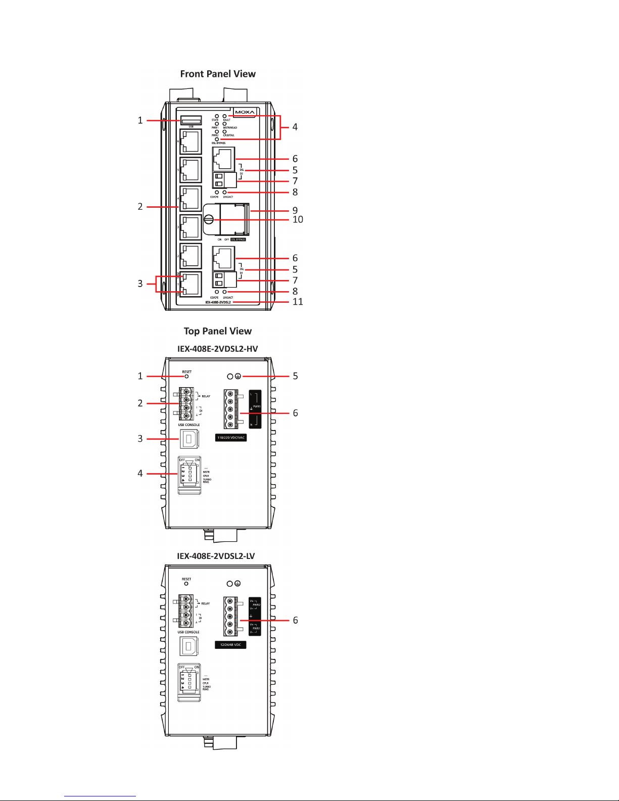
IEX-408E-2VDSL2 Panel Layout
Front Panel:
1. USB storage port (type A
connector)
2. 1 to 6: 10/100BaseT(X) port
3. 1 to 6 port status LED
• Upper LED: 100 Mbps
• Lower LED: 10 Mbps
4. System status LED:
• STATE LED indicator
• PWR1 LED indicator
• PWR2 LED indicator
• DSL BYPASS LED indicator
• FAULT LED indicator
• MSTR/HEAD LED indicator
• CPLR/TAIL LED indicator
5. D1 to D2: DSL port
6. DSL port (RJ-45/RJ-11
connector)
7. DSL port (Detachable 2-pin
terminal block)
8. D1 to D2 DSL port st
atus LED:
• CO/CPE LED indicator
• LNK/ACT LED indicator
9. 3-pin-DIP-switch for
controlling DSL Bypass mode
10.
Door screw
11.
Model name
Top Panel
:
1. RESET button
2. 4-pin terminal receptor for
relay output and digital input
3. USB console port (type B
connector)
4. 4-pin-DIP-switch for Turbo
Ring, Ring Master, and Ring
Coupler
5. Grounding screw (chassis
ground)
6. 5-pin terminal receptor for
power input(s)
• Universal high-voltage
(HV) model
(IEX-408E-2VDSL2-HV):
110/220 VDC/VAC (PWR
1)
• Redundant dual inputs
low-voltage (LV) model
(IEX-408E-2VDSL2-LV):
12/24/48 VDC (PWR 1)
and 12/24/48 VDC (PWR
2)
www.ipc2u.ru
www.moxa.pro
Page 5
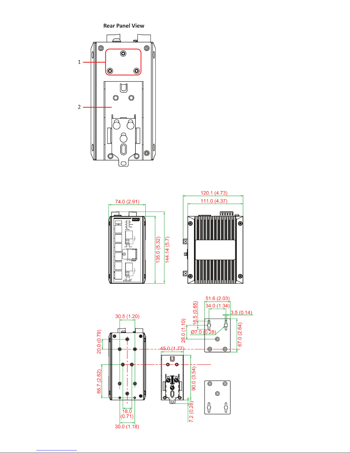
Rear Panel:
1.
Screw holes for wall mounting
kit
2. DIN-rail mounting kit
Mounting Dimensions - unit = mm (inches)
www.ipc2u.ru
www.moxa.pro
Page 6
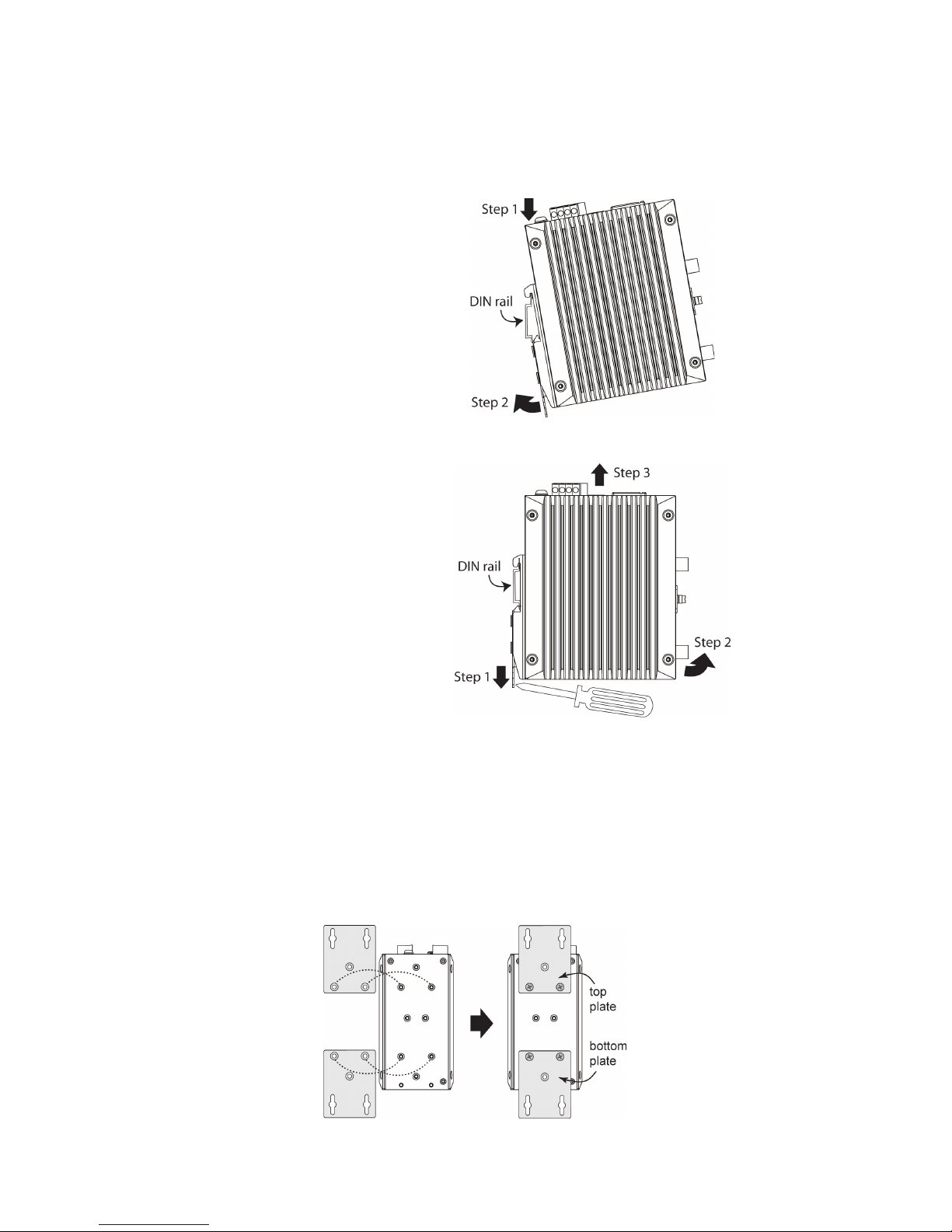
DIN-Rail Mounting
The metal DIN-rail mounting kit is fixed to the back panel of the
IEX-408E-2VDSL2. Mount the IEX-408E-2VDSL2 on the corrosion-free
mounting rail that meets the EN 60715 standard.
Installation
STEP 1—Insert the upper lip of
the DIN
-rail kit into the
mounting rail.
STEP 2
—Press the
IEX
-408E-2VDSL2 towards the
mounting rail until it snaps into
place.
Removal
STEP 1—Pull down the latch on
the DIN
-rail kit with a
screwdriver.
STEP 2 & 3
—Slightly pull the
IEX
-408E-2VDSL2 forward and
lift up to remove it from the
mounting rail.
Wall-Mounting (optional)
For some applications, you will find it convenient to mount the Moxa
IEX-408E-2VDSL2 on the wall, as shown in the following figures in this
section. Please follow below illustrations to install.
STEP 1—Remove the DIN rail attachment plate from the rear panel of the
IEX-408E-2VDSL2, and then attach the wall mount plates with M3 screws,
as shown in the figure below.
www.ipc2u.ru
www.moxa.pro
Page 7

STEP 2—Mounting the IEX-408E-2VDSL2 on the wall
requires 4 screws. Use the
IEX-408E-2VDSL2
, with wall
mount plates attached, as a guide to mark the location
of the 4 screws. The heads of the screws should be less
than 6.0 mm in diameter, and the shafts should be less
than 3.5
mm in diameter, as shown in the figure on
the
right.
NOTE
Before tightening the screws into the wall, make sure the screw
head and shank size are suitable by inserting the screw into one
of the keyhole-shaped apertures of the wall mounting plates.
STEP 3—Do not tighten the screws completely—leave about 2 mm to
allow room for sliding the wall mount panel between the wall and the
screws.
STEP 4—Once the screws are fixed
into the wall, insert the four screw
heads through the large parts of the
keyhole
-shaped ap
ertures, and then
slide the IEX
-408E-2VDSL2
downwards, as indicated in the
figure
on
the right. Tighten the four
screws for added stability.
Wiring Requirement
ATTENTION
Safety First!
Be sure to disconnect the power cord
before installing and/or
wiring your Moxa Ethernet Extender Switch.
Calculate the maximum possible current in each power wire and
common wire. Observe all electrical codes dictating the
maximum current allowable for each wire size.
If the current goes above the maximum ratings, the wiring could
overheat, causing serious damage to your equipment.
Be sure to read and follow these important guidelines:
• Use separate paths to route wiring for power and devices. If power
wiring and device wiring paths must cross, make sure the wires are
perpendicular at the intersection point.
NOTE
Do not run signal or communications wiring and power wiring
through the same wire conduit. To avoid interference, wires with
different signal characteristics should be routed separately.
• You can use the type of signal transmitted through a wire to
determine which wires should be kept separate. The rule of thumb is
that wiring that shares similar electrical characteristics can be
bundled together.
• You should separate input wiring from output wiring.
• We advise that you label the wiring to all devices in the system.
www.ipc2u.ru
www.moxa.pro
Page 8

Grounding the Moxa IEX-408E-2VDSL2 Ethernet
Extender Switch
Grounding and wire routing help limit the effects of noise due to
electromagnetic interference (EMI). Run the ground connection from the
ground screw (chassis ground) to the grounding surface prior to
connecting devices.
ATTENTION
This product is intended to be mounted onto a well
-grounded
mounting surface, such as a metal panel.
ATTENTION
Before powering on the IEX
-408E-2VDSL2, make sure that the
grounding cable is secured between the grounding screw (chassis
ground)
and the ground for surge protection (surge ground)
on
the 5
-pin terminal block for power inputs. Ground for surge
protection is on terminal 3 of the terminal block as shown below.
ATTENTION
For dielectric strength (HIPOT) test, users must remove the
grounding cable secured between the grounding screw (chassis
ground)
and ground for surge protection (surge ground)
located
at terminal 3 of the terminal block to avoid damage.
Wiring the Relay Contact
The IEX-408E-2VDSL2 has one set of relay outputs. These relay output
use two contacts of the 4-pin terminal block on the IEX-408E-2VDSL2’s
top panel.
Refer to the instructions below on how to connect the wires to the
terminal block connector, and how to attach the terminal block connector
to the terminal block receptor.
STEP 1—Insert the two wires into the RELAY terminals respectively to
form an open circuit.
STEP 2—To keep the RELAY wires from coming loose , use a small
flathead screwdriver to tighten the wire-clamp screws on the front of the
terminal block connector.
www.ipc2u.ru
www.moxa.pro
Page 9

ST
EP 3—Insert the plastic terminal block connector prongs into the
terminal block receptor, which is located on the IEX-408E-2VDSL2’s top
panel.
FAULT:
The two contacts of the 4-pin terminal block connector are used to detect
user-configured events. The two wires attached to the fault contacts form
an open circuit when a user-configured event is triggered. If a
user-configured event does not occur, the fault circuit remains closed.
Wiring the Digital Input
The IEX-408E-2VDSL2 has one set of digital input (DI). The DI consists of
two contacts of the 4-pin terminal block on the IEX-408E-2VDSL2’s top
panel, which are used for the two DC inputs.
Refer to the instructions below on how to connect the wires to the
terminal block connector, and how to attach the terminal block connector
to the terminal block receptor.
STEP 1: Insert the negative (ground)/positive DI wires into the ┴/I
terminals, respectively.
STEP 2: To keep the DI wires from coming loose, use a small flathead
screwdriver to tighten the wire-clamp screws on the front of the terminal
block connector.
STEP 3: Insert the plastic terminal block connector prongs into the
terminal block receptor, which is located on the IEX-408E-2VDSL2’s top
panel.
Wiring the Power Input (Universal high-voltage
(HV) model: 110/220 VDC/VAC)
The IEX-408E-2VDSL2 HV model (110/220 VDC/VAC) has one set of
power inputs (PWR 1)—Pin 1(V+/Line) and Pin5 (V-/Neutral). Insert the
5-pin terminal block connector prongs into the terminal block receptor on
IEX-408E-2VDSL2 HV unit properly. The top and front views of the
terminal block connector are also shown below.
www.ipc2u.ru
www.moxa.pro
Page 10

T
ake the following steps to wire the power input:
STEP 1: Insert the Line/Neutral AC or Positive/Negative DC wires into the
terminals (Terminal 1 for Line/Positive and Terminal 5 for
Neutral/Negative) of the terminal block connector.
STEP 2: To keep the AC or DC wires from coming loose, use a small
flathead screwdriver to tighten the wire-clamp screws on the front of the
terminal block connector.
STEP 3: Insert the plastic terminal block connector prongs into the
terminal block receptor, which is located on the IEX-408E-2VDSL2 HV
unit’s top panel.
NOTE
The IEX-408E-2VDSL2 HV model (110/220 VDC/VAC) has the
reverse protection mechanism for 110/220 VDC input.
ATTENTION
Before connecting the
IEX-408E-2VDSL2 HV model to the DC
power input, make sure the DC power source voltage is stable.
Wiring the Redundant Power Inputs (low-voltage
(LV) model: 12/24/48 VDC)
The IEX-408E-2VDSL2 LV model (12/24/48 VDC) has two sets of power
inputs –power input 1 (PWR 1) and power input 2 (PWR 2). Insert the
5-pin terminal block connector prongs into the terminal block receptor on
IEX-408E-2VDSL2 LV unit properly. Please take the following steps to
wire the redundant power inputs. The top and front views of the terminal
block connector are also shown below.
Take the following steps to wire the redundant power inputs:
STEP 1: Insert the Positive/Negative DC wires into the V1+/V1- terminal
for PWR 1 and/or V2+/V2- terminal for PWR 2.
STEP 2: To keep the DC wires from coming loose, use a small flathead
screwdriver to tighten the wire-clamp screws on the front of the terminal
block connector.
STEP 3: Insert the plastic terminal block connector prongs into the
terminal block receptor, which is located on the IEX-408E-2VDSL2 LV
unit’s top panel.
ATTENTION
Before connecting the
IEX-40E-
2VDSL2 to the DC power inputs,
make sure the DC power source voltage is stable.
www.ipc2u.ru
www.moxa.pro
Page 11

Communication Connections
Each IEX-408E-2VDSL2 extender switch has 4 types of communication
ports:
• 1 USB console port (type B connector)
• 1 USB storage port (type A connector)
• 6 10/100BaseT(X) Fast Ethernet ports
• 2 DSL (VDSL2 technology) ports
USB Console Connection
The IEX-408E-2VDSL2 has one USB console port (type B connector; see
below diagram for pinout assignments), located on the top panel. Use the
USB cable (provided in the product package) to connect this
IEX-408E-2VDSL2's USB console port to your PC's USB port and install
the USB driver (available in the software CD) on the PC. You may then use
a console terminal program, such as Moxa PComm Terminal Emulator, to
access the IEX-408E-2VDSL2’s console configuration utility.
USB Console Port (Type B Connector) Pinouts
Pin
Description
1
D– (Data -)
2
VCC (+5V)
3
D+ (Data+)
4
GND (Ground)
USB Storage Connection
The IEX-408E-2VDSL2 has one USB storage port (type A connector; see
below diagram for pinout assignments) on the front panel. Use Moxa
ABC-02-USB-T automatic backup configurator to connect this
IEX-408E-2VDSL2's USB storage port for configuration backup, firmware
upgrade or system log file backup.
USB Storage Port (Type A Connector) Pinouts
Pin
Description
1
VCC (+5V)
2
D– (Data -)
3
D+ (Data+)
4
GND (Ground)
NOTE
ABC
-02-USB Installation
Plug the ABC-02-USB into the
USB storage port of the Moxa
IEX
-408E-
2VDSL2. Securing the
ABC
-02-
USB on the wall with an
M4 screw is suggested.
www.ipc2u.ru
www.moxa.pro
Page 12

10/100BaseT(X) Ethernet Port Connection
The 10/100BaseT(X) ports located on the IEX’s front panel are used to
connect to Ethernet-enabled devices. Most users configure these ports for
Auto MDI/MDI-X mode, in which case the port's pinouts are adjusted
automatically depending on the type of Ethernet cable wiring
(straight-through or cross-over), and the type of device (NIC-type or
HUB/Switch-type) connected to the port.
Next, we show pinouts for both MDI (NIC-type) ports and MDI-X
(HUB/Switch-type) ports, and also show cable wiring diagrams for
straight-through and cross-over Ethernet cables.
MDI Port Pinouts
MDI-X Port Pinouts
8-pin RJ45
Pin
Signal
1
Tx+
2
Tx- 3 Rx+
6
Rx-
Pin
Signal
1
Rx+
2
Rx-
3
Tx+
6
Tx-
RJ45 (8-pin) to RJ45 (8-pin) Straight-Through Cable Wiring
RJ45 (8-pin) to RJ45 (8-pin) Cross-Over Cable Wiring
DSL Port Connection
The DSL ports located on the IEX-408E-2VDSL2 has two connection
options. One is the RJ45/RJ11 connector interface (2-wire on pin 4 and
pin 5; pinouts are illustrated below), the other is the screw detachable
2-pin terminal block interface. Refer to the instructions below on how to
connect the wires to the terminal block connector, and how to attach the
terminal block connector to the terminal block receptor.
www.ipc2u.ru
www.moxa.pro
Page 13

D
SL Port Pinouts for RJ45/RJ11 Connector
Pin
Signal
1 – 2 – 3 – 4
Ring
5
Tip 6 – 7 – 8 –
Wiring the 2-pin DSL Port
The 2-pin terminal block connectors on the IEX's front panel are used for
the IEX's DSL port wiring. Top and front views of the terminal block
connectors are shown below.
Step 1: Insert the wires into the Ring/Tip terminals.
Step 2:
To keep the wires from coming
loose, use a small
flat
head screwdriver to tighten the wire-
clamp screws on
the front of the terminal block connector.
Step 3:
Insert the plastic terminal block connector
prongs into the terminal block receptor, which is located
on the IEX’s
front panel.
Reset Button
There are two functions available on the reset button. One is to reset the
IEX Extender switch back to factory default settings and the other is quick
back up configuration and log files to the ABC-02-USB automatic backup
configurator.
Reset to Factory Default Settings
Use a pointed object, such as a straightened paper clip or toothpick, to
depress and hold the reset button for 5 seconds. This will cause the STATE
LED to blink once a second. After depressing the button for 5 continuous
seconds, the STATE LED will start to blink rapidly. This indicates that
factory default settings have been loaded and you can release the reset
button.
NOTE
Do NOT power off your Moxa Ethernet extender switch when the
default settings are loading.
Configuration and Log Files Back Up
When the ABC-02-USB is connected to the IEX extender switch, the reset
button allows quick back up of configuration and log files to the
ABC-02-USB. Press the reset button on top of the IEX-408E-2VDSL2, the
extender switch will start backing up current system configuration files
and event logs to the ABC-02-USB.
DIP Switches Settings
The IEX-408E-2VDSL2 contains 2 DIP switches. One for bypass mode
settings and the other for Turbo Ring redundancy settings.
www.ipc2u.ru
www.moxa.pro
Page 14

Bypass Mode DIP Switch Settings
The IEX-408E-2VDSL2 provides a 3-pin-DIP-switch which is located on
the front panel for DSL bypass mode configurations. Please open the
metal door first in order to adjust the mode and make sure you tighten
the screw on the front of the door every time you complete the settings.
Refer to below instructions on how to set the DSL bypass mode.
The default setting for each DIP switch is OFF. When all DIP
switches are set to ON positions
, as shown in the diagram
, it
enables bypass mode (you
will also see
the DSL BYPASS LED
light
up accordingly). (The DIP switches are in the OFF
position when located on the right.) Once the power supply of
the IEX
-408E-2VDSL2 is off, the bypass function will be
triggered and the two separate DSL connections will be linked
together accordingly and treated as a new pair/connection.
NOTE
Ensure all DIP switches have been set to ON positions in advance
in order to enable the bypass mode.
NOTE
Ensure you do a proper evaluation and calculation for each pair
and pairs with bypass mode enabled in between when enabling
bypass mode between DSL ports. Connection may not be able to
be established when conditions change, e.g. longer distance.
NOTE
Due to the characteristics of DSL technology, the DSL connection
needs to be
reestablished once it has become disconnected.
Therefore, when
the bypass function is triggered, you need to
wait up to a few minutes for the establishment of the new pair.
Turbo Ring DIP Switch Settings
IEX-408E-2VDSL2 series are plug-and-play managed redundant Ethernet
switches. The proprietary Turbo Ring protocol was developed by Moxa to
provide better network reliability and faster recovery times. Moxa Turbo
Ring’s recovery time is less than 300 ms (Turbo Ring) or 20 ms on Fast
Ethernet ports and 50 ms on DSL ports* (Turbo Ring V2) —compared to
a 3 to 5 minute recovery time for commercial switches—decreasing the
possible loss caused by network failures in an industrial setting.
www.ipc2u.ru
www.moxa.pro
Page 15

The
re is a 4-pin-DIP-switch for Turbo Ring on the top panel of the
IEX-408E-2VDSL2 that can help setup the Turbo Ring easily within
seconds. If you do not want to use a hardware DIP switch to setup the
Turbo Ring, you can use a web browser, telnet, or console to disable this
function.
NOTE
*50 ms of network recovery only applies when the DSL
connection links down from normal.
NOTE
Please refer to the Turbo Ring section in the Communication
Redundancy
User's Manual for more detailed
information about
the settings and usage of Turbo Ring and Turbo Ring V2.
The default setting for each DIP Switch is the OFF position. The following
table explains the effect of setting the DIP Switch to the ON position.
NOTE
The default mode when the DIP switch has been activated is set
to Turbo Ring V2 protocol
. If you want to switch to Turbo Ring
protocol, please change the settings via the web browser.
The
default ring ports are set to
the DSL D1/D2 ports with the Ring
Coupling or
the Primary ports are set to port 5 and the
Coupling
Control or Backup ports
are set to port 6 once you have activate
d
the redundant features through these DIP switches.
“Turbo Ring” DIP Switch Settings
DIP 1
DIP 2
DIP 3
DIP 4
Reserved for
future use.
ON: Enable
s this
IEX model as
the
Ring Master.
ON: Enables the
default “Ring
Coupling” ports.
ON: Activates
DIP switch 2 and
3 to configure
“Turbo Ring”
settings.
OFF: This IEX
model
will not be
the Ring Master.
OFF: Do not use
this IEX model
as
the ring coupler.
OFF: DIP switch
1, 2, and
3 will be
disabled.
www.ipc2u.ru
www.moxa.pro
Page 16

“T
urbo Ring V2” DIP Switch Settings
DIP 1
DIP 2
DIP 3
DIP 4
ON: Enables the
default “Ring
Coupling
(backup)” port
when DIP switch
3 is already
enabled.
ON: Enables this
IEX model as the
Ring Master.
ON: Enables the
default “Ring
Coupling” port.
ON: Activates
DIP switch 1, 2,
and 3 to
configure “Turbo
Ring V2”
settings.
OFF
: Enables the
default “Ring
Coupling
(primary)” port
when DIP switch
3 is already
enabled.
OFF: This IEX
model will not be
the Ring Master.
OFF: Do not use
this IEX model
as
a ring coupler.
OFF: DIP switch
1, 2, and
3 will be
disabled.
NOTE
You must enable the Turbo Ring function first before using the
DIP switch to activate the Master and Coupler functions.
NOTE
If you do not enable any of the IEX-408E-2VDSL2 switches to be
the Ring
Master, the Turbo Ring protocol will automatically
choose the IEX
-408E-2VDSL2 with the smallest MAC address
range to be the Ring Master. If you accidentally enable more than
one IEX
-408E-2VDSL2 to be the Ring Master, these
IEX
-408E-2VDSL2 switches will automatically negotiate to
determine which one will be the Ring Master.
CO/CPE automatic negotiation
The VDSL2 connection between 2 units (e.g. 2 IEX-408E-2VDSL2 and
connect one DSL port on one IEX from the other DSL port from the other
IEX) must operate in pair roles i.e. one port as CO with the other as CPE.
To make configuration easier, the IEX-408E-2VDSL2 supports auto
CO/CPE negotiation as the default setting on both DSL ports (DSL D1 and
DSL D2). When 2 DSL ports from Moxa’s IEX-408E-2VDSL2 or
IEX-402-VDSL2 are connected, auto CO/CPE negotiation will
automatically assign one port on one device as the CO and the other port
on the other side as the CPE.
Also, by factory default, the 2 DSL ports on one IEX-408E-2VDSL2 are set
for one to be CO (DSL D1) and the other to be CPE (DSL D2) with auto
CO/CPE negotiation enabled.
NOTE
To speed up
establishing a DSL connection, we suggest you
connect
the DSL D1 port on one IEX-408E-2VDSL2 to the
DSL D2
port on the other IEX-408E-2VDSL2 when installing.
NOTE
The CO/CPE roles on DSL ports can be set/changed through web
browser or Telnet/serial console interfaces.
www.ipc2u.ru
www.moxa.pro
Page 17

LED Indicators
LED
Color
State
Description
Per Device LED
PWR 1 Amber Solid light Power is being supplied to the main
system’s power input PWR1
Light off
Power is not being supplied to the main
system’s power input PWR1
PWR 2
Amber
Solid light
Power is being supplied to the main
system’s power input PWR2
Light off
Power is not being supplied to the main
system’s power input PWR2
STATE
Green
Solid light
System has passed self-diagnosis test on
boot-up and is ready to run
Blinking
1. System is undergoing the
self-diagnosis test
2. System detects ABC-02 USB plugged
into USB storage port
3. Blink continuously when pressing the
reset button for 5 seconds to reset to
factory default
4. Blink twice when pressing the reset
button for 2 seconds and release the
button for reboot
Red
Solid light
System failed self-diagnosis on boot-up.
FAULT
Red
Solid light
System is in the event of failure, or is
under quick inspection
Invalid port connection
Blinking
1. RAM test fail / switch Init. Fail
2. FW Checksum Fail / Uncompress Fail
Light off
The system is operating normally
MSTR/
HEAD
Green
Solid light
1. The switch is set as the Master of the
Turbo Ring, or as the Head of the
Turbo Chain.
2. POST H.W. Fail (+Stat on and Fault
blinking).
Blinking
1. The switch has become the Ring
Master of the Turbo Ring.
2.
The Head of the Turbo Chain, after the
Turbo Ring or the Turbo Chain is
down.
3. The switch is set as Turbo Chain’s
Member and the corresponding chain
port is down.
Light off 1. The switch is not the Master of this
Turbo Ring.
2. This switch is set as a Member of the
Turbo Chain.
www.ipc2u.ru
www.moxa.pro
Page 18

LED
Color
State
Description
Per Device LED
CPLR/
TAIL
Green Solid light 1. The switch’s coupling function is
enabled to form a back-up path.
2. When it’s set as the Tail of the Turbo
Chain.
3. POST S.W. Fail (+Stat on and Fault
blinking)
Blinking 1. Turbo Chain is down.
2. The switch is set as Turbo Chain’s
Member and the corresponding chain
port is down.
Light off
1. This switch has disabled the coupling
function.
2. This switch is set as a Member of the
Turbo Chain.
FAULT +
MSTR/HEAD +
CPLR/TAIL
Rotate
Blinking
Sequentially
ABC-02-USB is importing/exporting files
STATE + FAULT
+ MSTR/HEAD
+ CPLR/TAIL
Blinking DSL extender switch is being
discovered/located by MXview (2
times/s).
DSL
BYPASS
Green
Solid light
The certain device is acting in bypass
mode, i.e. the bypass redundant mode is
enabled on the DSL ports
Light off
The certain device is acting in normal
mode, i.e. the bypass redundant function
is not enabled on the DSL ports
Per DSL Port
CO/
CPE
Green
Solid light
The port is set as CPE
Light off
The corresponding port’s link is inactive
Amber
Solid light
The port is set as CO
Light off
The corresponding port’s link is inactive
LINK/
ACT
Green
Solid light
The corresponding port’s link is active
under STD mode
Blinking
The corresponding port is auto negotiating
for the optimized speed (Blink every 1 sec)
Light off
The corresponding port’s link is inactive
Per 100 Mbps Port LED
100M
Green
Solid Light
When there is a secure connection (or
link) to 100Mbps device at any port.
Blinking
When there is reception or transmission of
data occurring at 100Mbps.
Light off
Link down or no link
Per 10 Mbps Port LED
10M
Green
Solid Light
When there is a secure connection (or
link) to 10Mbps device at any port.
Blinking
When there is reception or transmission of
data occurring at 10Mbps.
Off
Link down or no link
www.ipc2u.ru
www.moxa.pro
Page 19

Specifications
Technology
Standards IEEE 802.3 for 10BaseT
IEEE 802.3u for 100BaseT(X) and 100BaseFX
IEEE 802.3ab for 1000BaseT(X)
IEEE 802.3z for 1000BaseX
IEEE 802.3x for Flow Control
IEEE 802.1D-2004 for Spanning Tree Protocols
IEEE 802.1w for Rapid STP
IEEE 802.1Q for VLAN Tagging
IEEE 802.1p for Class of Service
IEEE 802.1X for Authentication
IEEE 802.3ad for Port Trunk with LACP
ITU G.993.2 for very high speed digital
subscriber line transceivers 2
VDSL2 Data Rate
Up to 100Mbps depends on line condition
Management
SNMP v1/v2c/v3, LLDP, Syslog, RMON, DHCP
Server/Client, DHCP Option 66/67/82, BootP.
TFTP, SMTP, RARP, Telnet, SNMP Inform, Flow
Control, Back Pressure Flow Control
Filter
802.1Q VLAN, Port-Based VLAN, GVRP, IGMP
v1/v2/v3, GMRP
Redundancy Protocols STP, RSTP, MSTP, Turbo Ringv1/v2, Turbo
Chain, Link Aggregation
Security
RADIUS, TACACS+, SSL, SSH
Time Management
SNTP, NTP Server/Client
Industrial Protocols
EtherNet/IP, PROFINET IO, Modbus TCP
MIB MIB-II, Ethernet-Like MIB, P-BRIDGE MIB,
Q-BRIDGE MIB, Bridge MIB, RSTP MIB, RMON
MIB Group 1, 2, 3, 9
Interface
RJ45 Ports
10/100BaseT(X) auto negotiation speed, F/H
duplex mode, and auto MDI/MDI-X connection
DSL Port RJ-11(RJ-45 connector) or detachable 2-pin
terminal block
USB Ports
USB console port (type B connector);
USB storage port (type A connector)
LED Indicators
PWR1, PWR2, FAULT, STATE, MSTR/HEAD,
CPLR/TAIL, DSL BYPASS, 10/100M (TP port),
CO/CPE (DSL port), LINK/ACT (DSL port)
DIP Switches
Top 4-pin-DIP-switch:
TURBO RING, CPLR, MSTR
Front 3-pin-DIP-switch:
DSL BYPASS
Button
Reset button
Alarm Contact
1 relay output with current carrying capacity of
1 A @ 24 VDC
Digital Input
1 input with the same ground, but electrically
isolated from the electronics.
• +13 to +30V for state “1”
• -30 to +3V for state “0”
• Max. input current: 8 mA
www.ipc2u.ru
www.moxa.pro
Page 20

Power
Input Voltage
LV Models:
12/24/48 VDC (9.6 to 60 VDC) and -48 VDC,
isolated power and redundant dual inputs
HV Models:
110/220 VDC/VAC (88 to 300 VDC, 85 to 264
VAC), isolated power
Input Current Max. 1A @ 12 VDC
Max. 0.48A @ 24 VDC
Max. 0.26A @ 48 VDC
Max. 0.097A/0.050 @ 110/220 VDC
Max. 0.230A/0.149 @ 110/220 VAC
Connection
One removable 5-pin terminal block
Overload Current
Protection
Present
Reverse Polarity
Protection
Present
Physical Characteristics
Housing
Metal, IP30 protected
Dimension (W x H x D)
74 x 135 x 111 mm (2.91 x 5.32 x 4.37 in)
Weight
LV Models: 1.23 kg / HV Models 1.26 kg
Installation
DIN rail, wall-mount (optional kit)
Environmental Limits
Operating Temperature
-10 to 60°C (14 to 140°F);
-40 to 75°C (-40 to 167°F ) for -T models
Storage Temperature
-40 to 85°C (-40 to 185°F)
Ambient Relative
Humidity
5% to 95% (non-condensing)
Altitude Up to 2000 m, please contact Moxa for
products guaranteed to function at higher
altitudes
Regulatory Approvals
Safety
UL 61010-2-201
EMC
EN 55022/24
EMI
CISPR 22, FCC Part 15B Class A
EMS
EN 61000-4-2 (ESD): Contact: 8 kV; Air: 15 kV
EN 61000-4-
3 (RS): 80 MHz to 1 GHz, 10 V/m
EN 61000-4-4 (EFT): Power 4 kV
EN 61000-4-5 (Surge): Power 4 kV
EN 61000-4-6 (CS) 150 kHz to 80 MHz, 10 V/m
EN 61000-4-8 (PFMF)
Shock
IEC60068-2-27
Freefall
IEC60068-2-32
Vibration
IEC60068-2-6
Warranty
5 years
ATTENTION
This device complies with Part 15 of the FCC rules.
Operation is subject to the following conditions:
1.
This device may not cause harmful interference.
2.
This device must accept any interference received includ
ing
interference that may cause undesired operation.
www.ipc2u.ru
www.moxa.pro
 Loading...